EP0749924A1 - Method and apparatus for the welding of two webs, each coming from a supply roll, in a packaging machine - Google Patents
Method and apparatus for the welding of two webs, each coming from a supply roll, in a packaging machine Download PDFInfo
- Publication number
- EP0749924A1 EP0749924A1 EP96105246A EP96105246A EP0749924A1 EP 0749924 A1 EP0749924 A1 EP 0749924A1 EP 96105246 A EP96105246 A EP 96105246A EP 96105246 A EP96105246 A EP 96105246A EP 0749924 A1 EP0749924 A1 EP 0749924A1
- Authority
- EP
- European Patent Office
- Prior art keywords
- film
- supply roll
- rail
- film web
- web
- Prior art date
- Legal status (The legal status is an assumption and is not a legal conclusion. Google has not performed a legal analysis and makes no representation as to the accuracy of the status listed.)
- Withdrawn
Links
Images
Classifications
-
- B—PERFORMING OPERATIONS; TRANSPORTING
- B65—CONVEYING; PACKING; STORING; HANDLING THIN OR FILAMENTARY MATERIAL
- B65H—HANDLING THIN OR FILAMENTARY MATERIAL, e.g. SHEETS, WEBS, CABLES
- B65H19/00—Changing the web roll
- B65H19/10—Changing the web roll in unwinding mechanisms or in connection with unwinding operations
- B65H19/18—Attaching, e.g. pasting, the replacement web to the expiring web
- B65H19/1857—Support arrangement of web rolls
- B65H19/1873—Support arrangement of web rolls with two stationary roll supports carrying alternately the replacement and the expiring roll
-
- B—PERFORMING OPERATIONS; TRANSPORTING
- B65—CONVEYING; PACKING; STORING; HANDLING THIN OR FILAMENTARY MATERIAL
- B65H—HANDLING THIN OR FILAMENTARY MATERIAL, e.g. SHEETS, WEBS, CABLES
- B65H19/00—Changing the web roll
- B65H19/10—Changing the web roll in unwinding mechanisms or in connection with unwinding operations
- B65H19/18—Attaching, e.g. pasting, the replacement web to the expiring web
- B65H19/1842—Attaching, e.g. pasting, the replacement web to the expiring web standing splicing, i.e. the expiring web being stationary during splicing contact
- B65H19/1852—Attaching, e.g. pasting, the replacement web to the expiring web standing splicing, i.e. the expiring web being stationary during splicing contact taking place at a distance from the replacement roll
-
- B—PERFORMING OPERATIONS; TRANSPORTING
- B65—CONVEYING; PACKING; STORING; HANDLING THIN OR FILAMENTARY MATERIAL
- B65H—HANDLING THIN OR FILAMENTARY MATERIAL, e.g. SHEETS, WEBS, CABLES
- B65H2301/00—Handling processes for sheets or webs
- B65H2301/40—Type of handling process
- B65H2301/46—Splicing
- B65H2301/461—Processing webs in splicing process
- B65H2301/4615—Processing webs in splicing process after splicing
- B65H2301/4617—Processing webs in splicing process after splicing cutting webs in splicing process
- B65H2301/46176—Processing webs in splicing process after splicing cutting webs in splicing process cutting both spliced webs simultaneously
-
- B—PERFORMING OPERATIONS; TRANSPORTING
- B65—CONVEYING; PACKING; STORING; HANDLING THIN OR FILAMENTARY MATERIAL
- B65H—HANDLING THIN OR FILAMENTARY MATERIAL, e.g. SHEETS, WEBS, CABLES
- B65H2301/00—Handling processes for sheets or webs
- B65H2301/40—Type of handling process
- B65H2301/46—Splicing
- B65H2301/463—Splicing splicing means, i.e. means by which a web end is bound to another web end
- B65H2301/4634—Heat seal splice
-
- B—PERFORMING OPERATIONS; TRANSPORTING
- B65—CONVEYING; PACKING; STORING; HANDLING THIN OR FILAMENTARY MATERIAL
- B65H—HANDLING THIN OR FILAMENTARY MATERIAL, e.g. SHEETS, WEBS, CABLES
- B65H2801/00—Application field
- B65H2801/81—Packaging machines
Definitions
- the invention relates to a method for welding two film webs, each coming from a supply roll, in a packaging machine and to an apparatus for carrying out the method.
- the detector recognizes that the end of the film web wound on the first supply roll is approaching, the unwinding movement is stopped, the film webs lying parallel to one another are pressed against one another and welded, while the end of the film web of the is pressed with the aid of a cutting device arranged between the vacuum rail and the welding device first supply roll is cut off. During this time, the production process is not interrupted, since the amount of film stored in the dancer is sufficient for the packaging processes carried out during the sealing process.
- the known device has the disadvantage that it is structurally complex and therefore prone to failure.
- the welding of the foil webs lying parallel to each other means that the beginning of the foil of the new web remains on one side of the weld seam and a correspondingly long piece of the old foil web remains on the opposite side, and an increase in susceptibility to faults becomes an issue taken because in the downstream film cutting device, in which correspondingly long film sections are produced for the packaging process, pieces of the excess film ends are cut off in the vicinity of the welded area and fly uncontrollably in the machine.
- a long rod corresponding to the length of this rail is arranged parallel to the rail axis on the rail and can be moved away from it, which also coils when wrapping around the cylindrical rail is wrapped.
- the rod nail-off rod
- the rod gripped via a suitable mechanical coupling element and moved a short distance away from the surface of the cylindrical rail, so that it tears the welded film away from the respective heating strip, thereby enabling the weld seam to be cooled cleanly by the ambient air.
- the feature of claim 5 provides that a clamping strip that can be pressed against the cylindrical rail is provided on the cylindrical rail of the welding device between the parallel parallel film webs arriving from the deflection rollers. This causes the beginning of the film, after it has been placed around the cylindrical rail and the tear-off bar, to be held at an angle of 90 ° in a clockwise or counterclockwise direction from the respective welding point on the cylindrical rail. After the sealing process is finished and the sealed film web is transported further, the operator removes the remaining film sections before inserting a new roll.
- the film web feed is shown in a known type of packaging machine that is not otherwise shown. It consists of two film supply rolls 3 and 4 mounted on shafts 1 and 2 arranged parallel to one another, which are generally arranged below the production level.
- the film web 5 or 6 of the respective supply roll 3 or 4 is fed to a dancer as a storage device, from which it is fed to a cutting device.
- the film length required for each container is cut here.
- the resulting film section is passed diagonally upwards into the production level, where it is wrapped around the container, after which this preliminary pack passes through a shrink tunnel in which the film is shrunk tightly around the container under the action of heat.
- a heating strip 12 is arranged on the cylindrical rail, which cooperates with a pressure rail 13, which is arranged above the film web 6.
- a further heating strip 14 is arranged on the cylindrical rail 10, which in turn interacts with a pressure rail 15, which is arranged below the film web 5.
- the terminal block 11 and the pressure rails 13 and 15 are moved via a suitable, peneumatically or electromotively driven gear. This transmission or the drive is not shown for reasons of clarity.
- the film web feed is then switched on again.
- the film web 5 takes along the welded-on beginning of the film web 6 by lifting the section of the film web 6 wrapped around the cylindrical rail 10 up to the heating strip 14 off the cylindrical rail and now leading it to the dancer.
Abstract
Description
Die Erfindung betrifft ein Verfahren zum Verschweißen zweier von jeweils einer Vorratsrolle kommender Folienbahnen in einer Verpackungsmaschine sowie eine Vorrichtung zur Durchführung des Verfahrens.The invention relates to a method for welding two film webs, each coming from a supply roll, in a packaging machine and to an apparatus for carrying out the method.
Mit Hilfe der eingangs genannten Verpackungsmaschinen werden zuvor in Abteilstationen gebildete Produktgruppen, beispielsweise auf Trays stehende aber auch frei auf dem Förderband gruppierte Behälter wie Dosen, Flaschen etc. mit Folienabschnitten umwickelt und in einem anschließenden Schrumpftunnel wird das zunächst locker um die jeweilige Produktgruppe gelegte Folienmaterial fest um die Behälter geschrumpt.With the help of the packaging machines mentioned at the beginning, product groups previously formed in compartment stations, for example containers standing on trays but also freely grouped on the conveyor belt, such as cans, bottles etc., are wrapped with film sections and the film material, initially loosely laid around the respective product group, is fixed in a subsequent shrink tunnel shrunk around the container.
Die Folienabschnitte werden von Vorratsrollen geliefert, von denen in der Regel zwei - beispielsweise - unterhalb der Produktlinie angeordnet sind. Die von der Rolle kommende Folienbahn wird einem als Tänzer bezeichneten Speicher zugeführt, aus dem entsprechend der Taktzahl der Verpackungsvorgänge die jeweils benötigte Folienmenge abgezogen wird, die anschließend in einer Schneidvorrichtung abgelängt und zum Umschlingen der Produktgruppe weitergeleitet wird. Bei den heutzutage erreichten Taktzahlen reicht eine Vorratsrolle nur kurze Zeit, was bedeutet, daß auch die Frequenz des Umschaltens auf die jeweils andere volle Vorratsrolle hoch ist. Die die Maschine bedienende Person, der Operator, muß daher genau beobachten, wann die gerade liefernde Vorratsrolle zur Neige geht. Kurz vor dem Bahnende muß er die Maschine abstellen, damit er den Anfang der Folienbahn der zweiten jetzt vollen Rolle mit dem Ende der Folienbahn der fast leeren Rolle verschweißen kann.The film sections are supplied from supply rolls, two of which are usually arranged, for example, below the product line. The film web coming from the roll is fed to a memory called a dancer, from which the amount of film required in each case is drawn off in accordance with the number of cycles of the packaging processes, which is then cut to length in a cutting device and passed on for looping around the product group. With the number of cycles reached today, one supply roll is only sufficient for a short time, which means that the frequency of switching to the other full supply roll is also high. The person operating the machine, the operator, must therefore observe closely when the supply roll currently being used is running out. Shortly before the end of the web, he has to turn off the machine so that he can start the film web the second roll, which is now full, can be welded to the end of the film web of the almost empty roll.
Danach muß er die Maschine erneut starten und eine neue volle Vorratsrolle an die Stelle der leeren alten setzen.Then he has to start the machine again and put a new full supply roll in the place of the empty old one.
Ein derartiges Verfahren ist zum einen sehr zeitaufwendig, bringt unzumutbare Produktionspausen mit sich und bedingt praktisch die ständige Anwesenheit des Operators, damit dieser das Verschweißen der Folienbahnen rechtzeitig in Angriff nehmen kann.On the one hand, such a method is very time-consuming, entails unreasonable production breaks and practically requires the constant presence of the operator so that the operator can start welding the film webs in good time.
Um diese Nachteile zu beseitigen, ist im Stand der Technik bereits vorgeschlagen worden, die Verschweißung der Folienbahnen zu automatisieren.In order to eliminate these disadvantages, it has already been proposed in the prior art to automate the welding of the film webs.
So offenbart die EP-A-0 597 550 eine Vorrichtung, bei der die jeweils liefernde Vorratsrolle mit Hilfe eines Detektors bezüglich ihres Abwickelzustandes beobachtet wird. Die Folienbahn läuft dabei an einer Rolle vorbei, welche die Bahn an eine Unterdruckschiene drückt. Im folgenden verläuft die Bahn durch eine Verschweißeinrichtung und über diverse Umlenkrollen zum Tänzer. Die volle Vorratsrolle befindet sich während dieser Zeit in Ruhestellung. Der Anfang der von ihr kommenden Folienbahn läuft ebenfalls an einer Rolle vorbei, welche den Folienanfang auf die von der ersten Folienbahn abgewandte Seite der Unterdruckschiene drückt. Im weiteren Verlauf reicht dieser Folienanfang durch die Verschweißeinrichtung noch um ein Stück heraus. Erkennt der Detektor, daß sich das Ende der auf die erste Vorratsrolle gewickelten Folienbahn nähert, wird die Abwickelbewegung gestoppt, die parallel zueinander liegenden Folienbahnen werden aufeinander gedrückt und verschweißt, während mit Hilfe einer zwischen der Unterdruckschiene und der Verschweißvorrichtung angeordneten Schneidvorrichtung das Ende der Folienbahn der ersten Vorratsrolle abgeschnitten wird. Während dieser Zeit wird der Produktionsvorgang nicht unterbrochen, da die im Tänzer gespeicherte Folienmenge für die während des Verschweißvorganges ausgeführten Verpackungsvorgänge ausreichend ist.For example, EP-A-0 597 550 discloses a device in which the supply roll in each case is observed with respect to its unwinding state with the aid of a detector. The film web runs past a roll that presses the web against a vacuum rail. In the following, the web runs through a welding device and over various deflection rollers to the dancer. The full supply roll is at rest during this time. The beginning of the film web coming from it also runs past a roller which presses the beginning of the film onto the side of the vacuum rail facing away from the first film web. In the further course, this beginning of the film extends a little further through the welding device. If the detector recognizes that the end of the film web wound on the first supply roll is approaching, the unwinding movement is stopped, the film webs lying parallel to one another are pressed against one another and welded, while the end of the film web of the is pressed with the aid of a cutting device arranged between the vacuum rail and the welding device first supply roll is cut off. During this time, the production process is not interrupted, since the amount of film stored in the dancer is sufficient for the packaging processes carried out during the sealing process.
Die vorbekannte Vorrichtung weist jedoch zum einen den Nachteil auf, daß sie konstruktiv aufwendig und damit störungsanfällig ist. Zum anderen bringt es die Verschweißung der parallel zueinander liegenden Folienbahnen mit sich, daß auf der einen Seite der Schweißnaht der Folienanfang der neuen Bahn und auf der abgewandten Seite ein entsprechend langes Stück der alten Folienbahn verbleibt, und es wird dabei eine Erhöhung der Störanfälligkeit in Kauf genommen, da in der nachgeschalteten Folienschneideinrichtung, in der für den Verpackungsprozeß entsprechend lange Folienabschnitte hergestellt werden, beim Schneiden in der Nähe des verschweißten Bereichs Stücke der überschüssigen Folienenden abgetrennt werden und unkontrolliert in der Maschine herumfliegen.However, the known device has the disadvantage that it is structurally complex and therefore prone to failure. On the other hand, the welding of the foil webs lying parallel to each other means that the beginning of the foil of the new web remains on one side of the weld seam and a correspondingly long piece of the old foil web remains on the opposite side, and an increase in susceptibility to faults becomes an issue taken because in the downstream film cutting device, in which correspondingly long film sections are produced for the packaging process, pieces of the excess film ends are cut off in the vicinity of the welded area and fly uncontrollably in the machine.
Der Erfindung liegt daher die Aufgabe zugrunde, ein Verfahren der eingangs genannten Art so zuführen, daß eine saubere Schweißnaht ohne überstehende und überflüssige Folienabschnitte entsteht. Weiterhin liegt die Erfindung die Aufgabe zugrunde, eine Vorrichtung zur Ausführung des Verfahren anzugeben, die konstruktiv einfach aufgebaut ist.The invention is therefore based on the object of performing a method of the type mentioned at the outset in such a way that a clean weld seam is produced without protruding and superfluous sections of film. Furthermore, the invention is based on the object of specifying a device for carrying out the method which is of simple construction.
Die Erfindung löst diese Aufgaben mit Hilfe der Merkmale der Patentansprüche 1 und 2. Vorteilhafte Weiterbildungen der Erfindung sind Gegenstand der Unteransprüche.The invention solves these problems with the aid of the features of
Dadurch, daß der Anfang der Folienbahn von der vollen Vorratsrolle in Gegenrichtung zur laufenden Folienbahn von der sich leerenden Vorratsrolle in die Verschweißeinrichtung eingeführt ist, ergeben sich folgende Vorteile:The fact that the beginning of the film web is introduced into the sealing device from the full supply roll in the opposite direction to the running film web from the empty supply roll results in the following advantages:
Das Verschweißen der Folienbahnen miteinander ist kombiniert mit dem gleichzeitigen Abschneiden der überschüssigen Folienabschnitte. Im Bereich der Schweißnaht liegen die Folienabschnitte Kante auf Kante aufeinander. Wird die Folienzuführung erneut gestartet, heben sich die bisher aufeinander liegenden Folienabschnitte voneinander ab und sind mit ihren Kanten über eine schmale saubere Naht miteinander verbunden.The welding of the film webs to one another is combined with the simultaneous cutting of the excess film sections. In the area of the weld seam, the foil sections lie one on top of the other. If the film feed is started again, the previously lying film sections stand out from each other and their edges are connected to each other via a narrow, clean seam.
Im Gegensatz zum Stand der Technik wird beim erfindungsgemäßen Verfahren auf eine separate Schneidvorrichtung verzichtet, und trotzdem entstehen im Nahtbereich keine störenden Folienabfälle, die von der zusammengeschweißten Folienbahn mitgenommen würden und zu unansehnlich verpackten Produktgruppen führen.In contrast to the prior art, a separate cutting device is dispensed with in the method according to the invention, and nevertheless there are no disruptive film wastes in the seam area which would be carried along by the welded film web and lead to unsightly packaged product groups.
Gemäß der Erfindung besteht die Vorrichtung zur Durchführung des Verfahrens in der Hauptsache aus einer Folienverschweißeinrichtung, welche eine zylindrische Schiene aufweist, auf deren Umfang um 180° zueinander versetzt, in achsparalleler Richtung verlaufend je eine Heizleiste vorgesehen ist, mit der jeweils eine Andrückschiene korrespondiert, die mittels eines geeigneten, beispielsweise pneumatischen Antriebes auf die entsprechende Heizleiste zu- bzw. von dieser wegbewegbar ist. Diese zylindrische Schiene dient nicht nur als Tragelement für die Heizleisten sondern auch als Umlenkschiene für den Folienanfang der vollen Vorratsrolle. Die von der vollen Vorratsrolle kommende Folienbahn wird zwischen Heizleiste und Andrückschiene hindurch um mehr als 180° um die zylindrische Schiene herumgelegt und in dieser Position gehalten. Das umgelenkte Stück der Folienbahn liegt somit antiparallel zur laufenden Folienbahn, die zwischen der zweiten Heizleiste und der entsprechenden Andrückschiene hindurch verläuft. Für den Verschweißvorgang wird die laufende Folienbahn angehalten, die Andrückschiene drückt nun die antiparallel aufeinander liegenden Folien zusammen gegen die Heizleiste, wobei naturgemäß nur diese Heizleiste mit Strom beaufschlagt ist. Beim Verschweißen werden gleichzeitig die Folienbahnen entlang der Schweißnaht abgetrennt. Sobald die Andrückschiene von der Heizleiste entfernt ist, wird mit der Folienzuführung erneut begonnen. Gemäß dem Merkmal des Patentanspruchs 4 ist vorgesehen, daß auf der in Folienlaufrichtung hinteren Seite der zylindrischen Schiene ein der Länge dieser Schiene entsprechend langer Stab parallel zur Schienenachse an die Schiene anlegbarer und von dieser wegbewegbarer Stab angeordnet ist, der beim Umwickeln der zylindrischen Schiene ebenfalls mit umwickelt wird. Während des Öffnungsvorganges der Andrückschienen wird der Stab (Abreißstab) über ein geeignetes mechanisches Kupplungselement gegriffen und ein kurzes Stück von der Oberfläche der zylindrischen Schiene wegbewegt, sodaß er die verschweißte Folie von der jeweiligen Heizleiste wegreißt, wodurch ein sauberes Abkühlen der Schweißnaht durch die Umgebungsluft ermöglicht wird. Das Ergebnis ist eine Verbesserung der Haltbarkeit der Schweißnaht beim Wiederanfahren der Anlage (Erhöhung der Funktionssicherheit)
Das alles geschieht, ohne daß die Anwesenheit des Operators notwendig wäre. Seine Tätigkeit beschränkt sich somit nur noch darauf, daß er eine neue Vorratsrolle anstelle der abgewickelten aufsetzt und die Einfädelung des Folienanfangs vornimmt, was bei laufender Maschine geschehen kann. Abhängig von der Größe des Tänzers braucht beim Verschweißvorgang der Produktionsablauf nicht unterbrochen zu werden. Der Vorteil des kontinuierlichen Rollenwechsels war - wie oben ausgeführt - zwar auch schon im Stand der Technik gegeben, er wird erfindungsgemäß jedoch mit wesentlich einfacheren konstruktiven Maßnahmen erreicht, wie die Merkmale des Patentanspruchs 3 bzw. 4 zeigen.According to the invention, the device for carrying out the method mainly consists of a foil sealing device which has a cylindrical rail, on the circumference of which is offset by 180 ° to one another, a heating strip is provided running in the axis-parallel direction, with each of which a pressure rail corresponds can be moved toward or away from the corresponding heating strip by means of a suitable, for example pneumatic, drive. This cylindrical rail serves not only as a support element for the heating strips but also as a deflection rail for the beginning of the film of the full supply roll. The film web coming from the full supply roll is placed between the heating strip and the pressure rail by more than 180 ° around the cylindrical rail and held in this position. The deflected piece of the film web is thus antiparallel to the running film web, which runs between the second heating strip and the corresponding pressure rail. For the welding process, the running foil web is stopped, the pressure rail now presses the foils lying antiparallel on top of each other against the heating strip, whereby naturally only this heating strip is energized. When welding, the film webs along the weld seam are cut off at the same time. As soon as the pressure rail is removed from the heating bar, the film feed is started again. According to the feature of
All of this happens without the presence of the operator. His job is therefore only limited to putting on a new supply roll instead of the unwound one and threading the beginning of the film, which can happen while the machine is running. Depending on the size of the dancer, the production process does not have to be interrupted during the welding process. The advantage of the continuous roll change was - as stated above - already given in the prior art, but it is achieved according to the invention with much simpler design measures, as the features of patent claims 3 and 4 show.
Damit der antiparallel zur laufenden Folienbahn gerichtete Folienanfang der vollen Vorratsrolle sicher positionierbar ist, sieht das Merkmal des Patentanspruchs 5 vor, daß zwischen den von den Umlenkrollen ankommenden, parallel geführten Folienbahnen an der zylindrischen Schiene der Verschweißeinrichtung eine gegen die zylindrische Schiene anpressbare Klemmleiste vorgesehen ist. Diese bewirkt, daß der Folienanfang, nachdem er um die zylindrische Schiene und den Abreißstab herumgelegt worden ist, im Winkel von 90° im bzw. entgegen dem Uhrzeigersinn gerechnet von der jeweiligen Verschweißstelle an der zylindrischen Schiene festgehalten wird. Nachdem der Verschweißvorgang beendet ist und die verschweißte Folienbahn weitertransportiert wird, entfernt der Operator die verbliebenen Folienabschnitte, bevor er eine neue Rolle einsetzt.In order that the start of the full supply roll, which is directed antiparallel to the running film web, can be securely positioned, the feature of claim 5 provides that a clamping strip that can be pressed against the cylindrical rail is provided on the cylindrical rail of the welding device between the parallel parallel film webs arriving from the deflection rollers. This causes the beginning of the film, after it has been placed around the cylindrical rail and the tear-off bar, to be held at an angle of 90 ° in a clockwise or counterclockwise direction from the respective welding point on the cylindrical rail. After the sealing process is finished and the sealed film web is transported further, the operator removes the remaining film sections before inserting a new roll.
Zum Erkennen des Abwickelzustands der jeweils fördernden Vorratsrolle sind gemäß den Patentansprüchen 6 bzw. 7 elektrooptische Bauelemente wie z.B. Lichtschranken oder aber auch elektromechanische Bauteile vorgesehen.To identify the unwinding state of the respective supply roll, according to
Die Erfindung wird im folgenden anhand von Zeichnungen dargestellt und näher erläutert.The invention is illustrated below with reference to drawings and explained in more detail.
Es zeigen:
- Fig. 1a + b:
- Folienverschweißeinrichtung in einer ersten Phase,
- Fig. 2a + b:
- Folienverschweißeinrichtung in einer zweiten Phase.
- Fig. 1a + b:
- Foil sealing device in a first phase,
- 2a + b:
- Foil sealing device in a second phase.
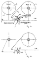
In den Figuren ist die Folienbahnzuführung in einer ansonsten nicht dargestellten Verpackungsmaschine bekannter Art gezeigt. Sie besteht aus zwei auf parallel zueinander angeordneten Wellen 1 und 2 gelagerten Folienvorratsrollen 3 und 4, die in der Regel unterhalb der Produktionsebene angeordnet sind. Die Folienbahn 5 oder 6 der jeweils liefernden Vorratsrolle 3 oder 4 wird einem Tänzer als Speichervorrichtung zugeleitet, von dem sie einer Schneidvorrichtung zugeführt wird. Hier wird die für jeweils ein Gebinde notwendige Folienlänge geschnitten. Der so entstandene Folienabschnitt wird schräg nach oben in die Produktionsebene geleitet, und dort wird er um das Gebinde geschlagen, wonach diese vorläufige Packung einen Schrumpftunnel durchläuft, in dem die Folie unter Wärmeeinwirkung fest um das Gebinde geschrumpft wird.In the figures, the film web feed is shown in a known type of packaging machine that is not otherwise shown. It consists of two
Da der Folienvorrat einer Vorratsrolle 3, 4 lediglich für einen Zeitraum ausreicht, der in der Größenordnung von etwa 30-60 min liegt(je nach Produktionsgeschwindigkeit und benötigter Folienlänge), muß die Folienbahn 5,6 der benachbarten, bislang ruhenden Vorratsrolle 3,4 ohne große Zeitunterbrechung an das Ende der von der ersten Vorratsrolle 4, 3 sich abwickelnden Folienbahn 6,5 durch Verschweißen angeschlossen werden. Hierzu durchlaufen die Folienbahnen 5,6 eine Verschweißeinrichtung, die schematisch dargestellt ist und allgemein mit dem Bezugszeichen 7 bezeichnet ist.Since the film supply of a
Die Folienbahnen werden um Umlenkrollen 8 und 9 herumgelenkt und parallel zueinander in gleicher Richtung verlaufend der Verschweißeinrichtung 7 zugeführt.The film webs are deflected around deflection rollers 8 and 9 and fed to the
In der Fig. 1a ist die Situation dargestellt, in der von der Vorratsrolle 3 die Folienbahn 5 um die Umlenkrolle 8 ungehindert durch die Verschweißeinrichtung 7 zum nicht dargestellten Tänzer geleitet wird. Die Folienbahn 6, die von der Vorratsrolle 4 um die Umlenkrolle 9 zur Verschweißeinrichtung 7 geführt ist, ist um eine zylindrische Schiene 10 und einen in Folienlaufrichtung an der hinteren Seite der Schiene 10 anliegenden Stab 19 (dessen Funktion weiter unten beschrieben wird) herumgeschlungen, derart, daß sie zwischen der zylindrischen Schiene 10 und der Folienbahn 5 nun antiparallel zu dieser verläuft und um weitere 90° an der zylindrischen Schiene 10 hochgeschlagen ist, in eine Position, in der sie von einer Klemmleiste 11 an der Schiene 10 gehalten wird. Dort, wo die Folienbahn 6 die zylindrische Schiene 10 tangential berührt, ist auf der zylindrischen Schiene eine Heizleiste 12 angeordnet, die mit einer Andrückschiene 13, die oberhalb der Folienbahn 6 angeordnet ist, zusammenwirkt. Auf der anderen Seite der zylindrischen Schiene, also um 180° zur Heizleiste 12 versetzt, ist eine weitere Heizleiste 14 auf der zylindrischen Schiene 10 angeordnet, die ihrerseits mit einer Andrückschiene 15, die unterhalb der Folienbahn 5 angeordnet ist, zusammenwirkt.FIG. 1 a shows the situation in which the film web 5 is passed unhindered from the supply roll 3 around the deflection roller 8 through the
Die Klemmleiste 11 sowie die Andrückschienen 13 bzw. 15 werden über ein geeignetes, peneumatisch bzw. elektromotorisch angetriebenes Getriebe bewegt. Dieses Getriebe bzw. der Antrieb ist aus Übersichtlichkeitsgründen nicht dargestellt.The
In der Fig. 1b ist nun der Zustand dargestellt, in der die Vorratsrolle 3 fast geleert ist. Der Abwickelgrad der jeweiligen Rolle wird in bekannter Weise durch beispielsweise eine Lichtschranke (ebenfalls nicht dargestellt) erkannt. Die Lichtschranke erzeugt dann ein Signal, das die weitere Zuführung von Folienbahnmaterial abschaltet. Die Andrückschienen 13 und 15 werden auf die zylindrische Schiene 10 gefahren und die Heizleiste 14 wird aktiviert, wodurch die antiparallel aufeinanderliegenden Folienbahnen 5 und 6 miteinander verschweißt und entlang der Naht (16) abgetrennt werden. Wenn nun die Andrückschienen 13 und 15 wieder in ihre Freigabeposition gefahren sind, wird der Stab 19 über ein geeignetes mechanisches Kupplungselement (nicht dargestellt) gegriffen und ein kurzes Stück von der Schiene 10 wegbewegt. Damit reißt er die Folie von der jeweiligen Heizleiste 12, 14 und ermöglicht damit ein sauberes Abkühlen der Schweißnaht durch die Umgebungsluft.Dann wird die Folienbahnzuführung wieder eingeschaltet. Die Folienbahn 5 nimmt dabei den angeschweißten Anfang der Folienbahn 6 mit, indem der um die zylindrische Schiene 10 bis zur Heizleiste 14 herumgewickelte Abschnitt der Folienbahn 6 von der zylindrischen Schiene abgehoben wird und nun zum Tänzer geführt wird.1b shows the state in which the supply roll 3 is almost emptied. The degree of unwinding of the respective roll is recognized in a known manner by, for example, a light barrier (also not shown). The light barrier then generates a signal which switches off the further supply of film web material. The pressure rails 13 and 15 are moved onto the
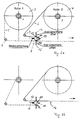
In den Fig. 2a und b ist der Fall dargestellt, bei dem nun die Vorratsrolle 4 abgewickelt wird, während die Vorratsrolle 3 zunächst in Ruhe bleibt. In diesem Fall ist die Folienbahn 5 von unten um die zylindrische Schiene 10 und den Stab 19 zwischen der Folienbahn 6 und der zylindrischen Schiene 10 um etwas mehr als 180° herumgeführt und wird dort von der Klemmleiste 11 gehalten.2a and b show the case in which the
Ist nun die Vorratsrolle 4 so gut wie abgewickelt, gibt der dieser Rolle zugeordnete Rollenzustandsdetektor das Signal zum Stoppen der Folienzuführung und zur Aktivierung der Heizleiste 12. Nach dem Verschweißen der beiden Folienbahnen 5 und 6 und dem Abtrennen der überschüssigen Endstücke 17,18 wird die Folienzuführung wieder aufgenommen, wie es die Fig. 2b zeigt.If the
Claims (7)
dadurch gekennzeichnet,
daß der Anfang der Folienbahn (5,6), die zu der zunächst ruhenden vollen Vorratsrolle (3,4) gehört, gegen die Laufrichtung der von der sich leerenden Vorratsrolle (4,3) kommenden Folienbahn (6,5) umgelenkt und gehalten ist und nach automatischem Erkennen des Abwickelzustands der laufenden Folienbahn (6,5) ein Signal zum Stoppen zumindest der Folienzuführung erzeugt wird, welches nach dem Stoppen ein Zusammenpressen und Verschweißen der antiparallel zueinander verlaufenden Folienbahnen (5,6) über deren gesamte Breite veranlaßt, wodurch gleichzeitig an der Schweißnaht (16) die überschüssigen Endstücke (17,18) der Folienbahn (5,6) abgetrennt werden, wonach ein weiteres Signal erzeugt wird, durch welches die Folienzuführung erneut gestartet wird.Process for welding two film webs, each coming from a supply roll, in a packaging machine
characterized,
that the beginning of the film web (5,6), which belongs to the initially stationary full supply roll (3,4), is deflected and held against the running direction of the film web (6,5) coming from the empty supply roll (4,3) and after automatic detection of the unwinding state of the running film web (6,5), a signal for stopping at least the film feed is generated, which after stopping causes the film webs (5,6), which run antiparallel to one another, to be compressed and welded over their entire width, thereby simultaneously the excess end pieces (17, 18) of the film web (5, 6) are cut off at the weld seam (16), after which a further signal is generated, by means of which the film feed is started again.
dadurch gekennzeichnet,
daß die Folienverschweißeinrichtung (7) eine zylindrische Schiene (10) aufweist, auf deren Umfang um 180 ° zueinander versetzt, in achsparalleler Richtung verlaufend je eine Heizleiste (12,14) vorgesehen ist, mit der jeweils eine Andrückschiene (13,15) korrespondiert, die mittels eines Antriebs auf die entsprechende Heizleiste (12,14) zu- bzw. von dieser wegbewegbar ist, und jedem Detektorelement eine der Heizleisten (12,14) eindeutig zugeordnet ist.Apparatus for carrying out the method according to claim 1, with two winding shafts arranged next to one another for receiving a film web supply roll each and a film welding device arranged below the winding shafts, and a detector element assigned to each supply roll for detecting the unwinding state the respective supply roll, which is electrically connected to the machine control and via this to the welding device,
characterized,
that the film welding device (7) has a cylindrical rail (10), on the circumference of which is offset by 180 ° to one another, a heating strip (12, 14) is provided running in the axis-parallel direction, with each of which a pressure rail (13, 15) corresponds, which can be moved towards or away from the corresponding heating strip (12, 14) by means of a drive, and one of the heating strips (12, 14) is uniquely assigned to each detector element.
dadurch gekennzeichnet,
daß in Folienlaufrichtung an der hinteren Seite der zylindrischen Schiene (10) ein der Länge der Schiene (10) entsprechender Stab (19) an die Schiene (10) anlegbarer und von dieser wegbewegbarer Stab (19) angeordnet ist.Device according to claim 2,
characterized,
that in the film running direction on the rear side of the cylindrical rail (10) a rod (19) corresponding to the length of the rail (10) is arranged on the rail (10) and can be moved away from it (19).
dadurch gekennzeichnet,
daß jeder Vorratsrolle (3,4) eine Umlenkrolle (8,9) zugeordnet ist, durch die die Folienbahnen (5,6) beider Vorratsrollen in gleicher Richtung und parallel zueinander der Verschweißeinrichtung (7) zuführbar sind, wobei die Folienbahn (5) der einen Vorratsrolle (3) zwischen der zylindrischen Schiene (10) und der einen Andrückschiene (15) und die Folienbahn (6) der anderen Vorratsrolle (4) zwischen der zylindrischen Schiene (10) und der anderen, gegenüberliegenden Andrückschiene (13) hindurchgeführt ist und die zylindrische Schiene (10) als Umlenkelement für den Anfang der von der vollen Vorratsrolle (3,4) kommenden Folienbahn (5,6) dient, um welches der Folienbahnanfang um mehr als 180° herum - und zwischen der von der sich leerenden Vorratsrolle (4,3) kommenden Folienbahn (6,5) und der zylindrischen Schiene (10) hindurchgeführt ist.Device according to claim 2 or 3,
characterized,
that each supply roll (3,4) is assigned a deflection roller (8,9), through which the film webs (5,6) of both supply rolls can be fed in the same direction and parallel to each other to the welding device (7), the film web (5) a supply roll (3) between the cylindrical rail (10) and one pressure rail (15) and the film web (6) of the other supply roll (4) between the cylindrical rail (10) and the other, opposite pressure rail (13) and the cylindrical rail (10) serves as a deflection element for the beginning of the film web (5,6) coming from the full supply roll (3,4), around which the beginning of the film web is rotated by more than 180 ° - and between that of the empty supply roll ( 4,3) coming foil web (6,5) and the cylindrical rail (10) is passed.
dadurch gekennzeichnet,
daß zwischen den von den Umlenkrollen (8,9) ankommenden, parallel geführten Folienbahnen (5,6) an der zylindrischen Schiene (10) der Verschweißeinrichtung (7) eine gegen die zylindrische Schiene (10) anpressbare Klemmleiste (11) vorgesehen ist.Device according to one of claims 2 to 4,
characterized,
that a clamping strip (11) which can be pressed against the cylindrical rail (10) is provided on the cylindrical rail (10) of the welding device (7) between the parallel guided film webs (5,6) arriving from the deflection rollers (8,9).
dadurch gekennzeichnet,
daß die Detektorelemente elektrooptische Bauelemente sind.Device according to one of claims 2 to 5,
characterized,
that the detector elements are electro-optical components.
dadurch gekennzeichnet,
daß die Detektorelemente elektromechanische Elemente sind.Device according to one of claims 2 to 5,
characterized,
that the detector elements are electromechanical elements.
Applications Claiming Priority (2)
| Application Number | Priority Date | Filing Date | Title |
|---|---|---|---|
| DE1995122110 DE19522110A1 (en) | 1995-06-19 | 1995-06-19 | Process for welding two film webs, each coming from a supply roll, in a packaging machine |
| DE19522110 | 1995-06-19 |
Publications (1)
| Publication Number | Publication Date |
|---|---|
| EP0749924A1 true EP0749924A1 (en) | 1996-12-27 |
Family
ID=7764636
Family Applications (1)
| Application Number | Title | Priority Date | Filing Date |
|---|---|---|---|
| EP96105246A Withdrawn EP0749924A1 (en) | 1995-06-19 | 1996-04-02 | Method and apparatus for the welding of two webs, each coming from a supply roll, in a packaging machine |
Country Status (2)
| Country | Link |
|---|---|
| EP (1) | EP0749924A1 (en) |
| DE (1) | DE19522110A1 (en) |
Cited By (7)
| Publication number | Priority date | Publication date | Assignee | Title |
|---|---|---|---|---|
| EP1439125A2 (en) * | 2003-01-16 | 2004-07-21 | Emil Pester GmbH | Wrapping machine |
| WO2007012104A1 (en) * | 2005-07-29 | 2007-02-01 | Karl Deininger | Method and apparatus for joining two webs of material |
| EP1757552A2 (en) * | 2005-08-25 | 2007-02-28 | Ingersoll Machine Tools, Inc. | Auto-splice apparatus and method for a fiber placement machine |
| NL1035313C2 (en) * | 2008-04-18 | 2009-10-20 | Pmb Uva Internat B V | Film connection establishment, has depleted film role whose rear edge is connected to front of full film role, where depleted and full film rolls connected to normal transport direction of moving parts |
| WO2009148910A2 (en) * | 2008-05-29 | 2009-12-10 | Ranpak Corp. | System and method for supplying stock material to a dunnage converter |
| EP2390212A2 (en) | 2010-05-27 | 2011-11-30 | Krones AG | Splicing device and method for splicing a sheet-like flat material |
| DE102004032528C5 (en) * | 2004-07-06 | 2012-04-05 | Khs Gmbh | A method of performing a roll change in a supply unit for feeding a sheet-like sheet to a packaging machine or the like processing machine and supply unit for performing this method |
Families Citing this family (9)
| Publication number | Priority date | Publication date | Assignee | Title |
|---|---|---|---|---|
| DE102004017098A1 (en) * | 2004-04-07 | 2005-10-27 | Illinois Tool Works Inc., Glenview | Auto-splice system |
| DE102006037189A1 (en) * | 2006-08-09 | 2008-02-14 | Khs Ag | A method of performing a roll change in a supply unit for feeding a sheet-like sheet to a packaging machine or the like processing machine and supply unit for performing this method |
| DE102015208126A1 (en) | 2015-04-30 | 2016-11-03 | Krones Aktiengesellschaft | Supply roll with function marking, method for handling flat and / or strip material wound up on supply rolls and system for handling flat and / or strip material |
| DE102015113496A1 (en) | 2015-08-14 | 2017-02-16 | Krones Aktiengesellschaft | Supply roll with at least one predetermined breaking point and method for handling such a supply roll |
| DE102015113497A1 (en) | 2015-08-14 | 2017-02-16 | Krones Aktiengesellschaft | Supply roll with at least one spacer and method for handling such a supply roll |
| DE102016215024A1 (en) | 2016-08-11 | 2018-02-15 | Krones Aktiengesellschaft | Method and device for collecting packaging material on a supply roll and system with such a device |
| DE102016215025A1 (en) | 2016-08-11 | 2018-02-15 | Krones Aktiengesellschaft | Method and apparatus for handling supply rolls, which carry packaging material on a roll core with a plurality of windings |
| DE102017121670A1 (en) | 2017-09-19 | 2019-03-21 | Krones Aktiengesellschaft | Supply roll with adhesive marking and method for handling flat and / or strip material |
| CN109534052B (en) * | 2018-12-25 | 2020-10-23 | 广州市万世德智能装备科技有限公司 | Automatic film connecting device |
Citations (5)
| Publication number | Priority date | Publication date | Assignee | Title |
|---|---|---|---|---|
| GB1184591A (en) * | 1967-01-04 | 1970-03-18 | Lerner Machine Company Ltd | Apparatus for Supplying Wrapping Material of Thermoplastic Synthetic Resin to Wrapping Apparatus. |
| EP0464003A1 (en) * | 1990-06-06 | 1992-01-02 | SASIB PACKAGING ITALIA S.r.L. | Method and apparatus for joining ends of webs of weldable film, for the formation of bags and the like |
| EP0472245A1 (en) * | 1990-08-24 | 1992-02-26 | Shikoku Kakoki Co., Ltd. | Apparatus for continuously unwinding a plurality of rolled-up tapes |
| EP0556534A1 (en) * | 1992-02-18 | 1993-08-25 | GARIBALDO RICCIARELLI S.r.l. | Device for joining strips of film of weldable material, with means of secure retention of the leading end of the film to be welded |
| WO1995009794A1 (en) * | 1993-10-05 | 1995-04-13 | The Procter & Gamble Company | Method and apparatus for heat splicing thermoplastic film |
-
1995
- 1995-06-19 DE DE1995122110 patent/DE19522110A1/en not_active Withdrawn
-
1996
- 1996-04-02 EP EP96105246A patent/EP0749924A1/en not_active Withdrawn
Patent Citations (5)
| Publication number | Priority date | Publication date | Assignee | Title |
|---|---|---|---|---|
| GB1184591A (en) * | 1967-01-04 | 1970-03-18 | Lerner Machine Company Ltd | Apparatus for Supplying Wrapping Material of Thermoplastic Synthetic Resin to Wrapping Apparatus. |
| EP0464003A1 (en) * | 1990-06-06 | 1992-01-02 | SASIB PACKAGING ITALIA S.r.L. | Method and apparatus for joining ends of webs of weldable film, for the formation of bags and the like |
| EP0472245A1 (en) * | 1990-08-24 | 1992-02-26 | Shikoku Kakoki Co., Ltd. | Apparatus for continuously unwinding a plurality of rolled-up tapes |
| EP0556534A1 (en) * | 1992-02-18 | 1993-08-25 | GARIBALDO RICCIARELLI S.r.l. | Device for joining strips of film of weldable material, with means of secure retention of the leading end of the film to be welded |
| WO1995009794A1 (en) * | 1993-10-05 | 1995-04-13 | The Procter & Gamble Company | Method and apparatus for heat splicing thermoplastic film |
Cited By (12)
| Publication number | Priority date | Publication date | Assignee | Title |
|---|---|---|---|---|
| EP1439125A2 (en) * | 2003-01-16 | 2004-07-21 | Emil Pester GmbH | Wrapping machine |
| EP1439125A3 (en) * | 2003-01-16 | 2006-03-22 | Emil Pester GmbH | Wrapping machine |
| DE102004032528C5 (en) * | 2004-07-06 | 2012-04-05 | Khs Gmbh | A method of performing a roll change in a supply unit for feeding a sheet-like sheet to a packaging machine or the like processing machine and supply unit for performing this method |
| WO2007012104A1 (en) * | 2005-07-29 | 2007-02-01 | Karl Deininger | Method and apparatus for joining two webs of material |
| EP1757552A2 (en) * | 2005-08-25 | 2007-02-28 | Ingersoll Machine Tools, Inc. | Auto-splice apparatus and method for a fiber placement machine |
| EP1757552A3 (en) * | 2005-08-25 | 2007-08-08 | Ingersoll Machine Tools, Inc. | Auto-splice apparatus and method for a fiber placement machine |
| NL1035313C2 (en) * | 2008-04-18 | 2009-10-20 | Pmb Uva Internat B V | Film connection establishment, has depleted film role whose rear edge is connected to front of full film role, where depleted and full film rolls connected to normal transport direction of moving parts |
| WO2009148910A2 (en) * | 2008-05-29 | 2009-12-10 | Ranpak Corp. | System and method for supplying stock material to a dunnage converter |
| WO2009148910A3 (en) * | 2008-05-29 | 2010-05-20 | Ranpak Corp. | System and method for supplying stock material to a dunnage converter |
| EP2390212A2 (en) | 2010-05-27 | 2011-11-30 | Krones AG | Splicing device and method for splicing a sheet-like flat material |
| DE102010021732A1 (en) | 2010-05-27 | 2011-12-01 | Krones Ag | Splicing device and method for splicing a web-like sheet |
| US8381787B2 (en) | 2010-05-27 | 2013-02-26 | Krones Ag | Splicing device and method for splicing a sheet-like flat material |
Also Published As
| Publication number | Publication date |
|---|---|
| DE19522110A1 (en) | 1997-01-02 |
Similar Documents
| Publication | Publication Date | Title |
|---|---|---|
| EP0749924A1 (en) | Method and apparatus for the welding of two webs, each coming from a supply roll, in a packaging machine | |
| EP1922253B1 (en) | Banding a stack of articles | |
| EP1600412B1 (en) | Film splicing device | |
| EP2390212B1 (en) | Splicing device and method for splicing a sheet-like flat material | |
| EP1439125B1 (en) | Wrapping machine | |
| DE19549664C2 (en) | Device for packaging a roll of material web | |
| EP0176789A2 (en) | Method and device for changing web rolls in connection with packaging machines | |
| DE4408814A1 (en) | Method and device for the automatic connection of the webs unwound from spools | |
| DE3727339A1 (en) | Device for exchanging film webs wound on a supply roll | |
| EP0382011A1 (en) | Apparatus for attaching without interruption a replacement web to an expiring web | |
| EP1888439B1 (en) | Device and method for connecting the ends of two flat tubular webs | |
| EP0609680B1 (en) | Method and device for splicing material webs | |
| EP0427126B1 (en) | Device for changing a band | |
| DE19652451A1 (en) | Device and method for packaging a roll of material web | |
| EP0759396B1 (en) | Device and method for packaging a roll of web material | |
| DE4212167C2 (en) | Method and device for connecting a paper web threading part with a paper web | |
| DE19601668A1 (en) | Rotary and rotating plate type winding machines for spiral film wrapping of loaded pallets | |
| DE3639972A1 (en) | Process and device for separating out from a material web material web sections which are unusable as a result of defects | |
| EP0963909A1 (en) | Method and device for making a circumferentially packaged roll of web material, and a roll of web material | |
| EP3885274A2 (en) | Packaging machine and method for packaging a product with packaging produced from an upper paper sheet and a lower paper sheet | |
| DE19652450C2 (en) | Device for packaging a roll of material web | |
| DE10243464B4 (en) | Method and device for packaging a material web roll | |
| EP3696098B1 (en) | Method for operating, in particular resetting, a film packing machine and film packing machine | |
| DE102020108161B4 (en) | Method of packaging products | |
| DE102020106030B4 (en) | Longitudinal separation welding device for a packaging machine and method for packaging a packaged goods with an outer packaging produced from an upper paper web and a lower paper web |
Legal Events
| Date | Code | Title | Description |
|---|---|---|---|
| PUAI | Public reference made under article 153(3) epc to a published international application that has entered the european phase |
Free format text: ORIGINAL CODE: 0009012 |
|
| AK | Designated contracting states |
Kind code of ref document: A1 Designated state(s): BE DE ES FR GB IT NL PT |
|
| STAA | Information on the status of an ep patent application or granted ep patent |
Free format text: STATUS: THE APPLICATION IS DEEMED TO BE WITHDRAWN |
|
| 18D | Application deemed to be withdrawn |
Effective date: 19970628 |