EP0749384B1 - Procede de recuperation d'une cargaison a bord d'une epave - Google Patents
Procede de recuperation d'une cargaison a bord d'une epave Download PDFInfo
- Publication number
- EP0749384B1 EP0749384B1 EP95911382A EP95911382A EP0749384B1 EP 0749384 B1 EP0749384 B1 EP 0749384B1 EP 95911382 A EP95911382 A EP 95911382A EP 95911382 A EP95911382 A EP 95911382A EP 0749384 B1 EP0749384 B1 EP 0749384B1
- Authority
- EP
- European Patent Office
- Prior art keywords
- wreck
- drill string
- pincer
- cargo
- shock absorber
- Prior art date
- Legal status (The legal status is an assumption and is not a legal conclusion. Google has not performed a legal analysis and makes no representation as to the accuracy of the status listed.)
- Expired - Lifetime
Links
- 238000000034 method Methods 0.000 title claims abstract description 15
- 238000011084 recovery Methods 0.000 title claims abstract description 7
- 210000000080 chela (arthropods) Anatomy 0.000 claims abstract description 27
- XLYOFNOQVPJJNP-UHFFFAOYSA-N water Substances O XLYOFNOQVPJJNP-UHFFFAOYSA-N 0.000 claims abstract description 6
- 230000035939 shock Effects 0.000 claims abstract 5
- 238000005553 drilling Methods 0.000 claims description 9
- 239000006096 absorbing agent Substances 0.000 claims 4
- 239000000383 hazardous chemical Substances 0.000 abstract 1
- 239000012857 radioactive material Substances 0.000 abstract 1
- 238000013016 damping Methods 0.000 description 7
- 239000002360 explosive Substances 0.000 description 3
- 230000006835 compression Effects 0.000 description 2
- 238000007906 compression Methods 0.000 description 2
- 239000003380 propellant Substances 0.000 description 2
- 229910000831 Steel Inorganic materials 0.000 description 1
- 230000001133 acceleration Effects 0.000 description 1
- 238000007796 conventional method Methods 0.000 description 1
- 230000006378 damage Effects 0.000 description 1
- 239000002184 metal Substances 0.000 description 1
- 230000002285 radioactive effect Effects 0.000 description 1
- 230000000284 resting effect Effects 0.000 description 1
- 239000013049 sediment Substances 0.000 description 1
- 239000010959 steel Substances 0.000 description 1
- 230000001360 synchronised effect Effects 0.000 description 1
Images

Classifications
-
- B—PERFORMING OPERATIONS; TRANSPORTING
- B63—SHIPS OR OTHER WATERBORNE VESSELS; RELATED EQUIPMENT
- B63C—LAUNCHING, HAULING-OUT, OR DRY-DOCKING OF VESSELS; LIFE-SAVING IN WATER; EQUIPMENT FOR DWELLING OR WORKING UNDER WATER; MEANS FOR SALVAGING OR SEARCHING FOR UNDERWATER OBJECTS
- B63C7/00—Salvaging of disabled, stranded, or sunken vessels; Salvaging of vessel parts or furnishings, e.g. of safes; Salvaging of other underwater objects
- B63C7/16—Apparatus engaging vessels or objects
- B63C7/20—Apparatus engaging vessels or objects using grabs
Definitions
- the present invention relates to a method of recovering a cargo on board a wreck sunk at great depth.
- Recovering a cargo trapped inside a wreck is a very difficult task. It requires that an access through the wreck be arranged. This access can be done through hatch panels, if the configuration allows (wreck resting horizontally on the bottom). It can be done through the hull, if the wreck is lying or overturned on the bottom.
- the wreck is cut using explosives or flame-cutting torches used by divers.
- the cargo is recovered using conventional lifting means (skips implemented from anchored barges for example).
- the process which is the subject of the invention makes it possible to solve both the problems of dismantling the hull and those of recovering the cargo, and this, by great depth.
- the object of the invention consists in implementing a pincer of high capacity from such ships by means of an underwater module responsible for moving it and actuating it under the control of cameras.
- the invention relates to a method for recovering a cargo trapped on board a wreck sunk at great depth, from a dynamically positioned drilling vessel. This process is characterized by the fact that the dismantling of the wreckage is carried out by means of pincers and a damping device arranged at the bottom of the rod train.
- the invention also relates to a device for dismantling a wreck sunk at great depth, from a dynamically positioned drilling vessel.
- This device is characterized in that it consists of a pincer and a damping device arranged at the lower part of the rod train.
- the closing force of the jaws of the pincers actuated by means of jacks is such (several hundreds of tons) that they can manage to tear the walls of the wreck in order to access the cargo.
- the pincers are equipped with side walls and are used in the same way as a bucket of several cubic meters of capacity.
- the pincers are tightened powerfully on the structure to be dismantled. It is then hoisted vertically so as to tear off the piece caught between its jaws. The pieces removed are more or less large depending on the tear lines obtained. Some pieces resist better than others and it is sometimes impossible to tear them off without risking the breaking of the drill string.
- the pincers are then moved slightly and, in general, after several attempts, tearing occurs. This work of destruction by tearing off after tightening is very different from the work of collecting grapples conventional.
- the damping device is essential for implementing the method. Indeed, at great depths, under the maximum traction force, the total elongation of the rod train is about 10m.
- the accumulated energy of the "mass-spring" system is such that without the damping device, the entire module and the pincers would go up, during pulling out, with strong acceleration, much higher than the equilibrium position . This would cause an uncontrolled buckling of the drill string with the risk of rupture.
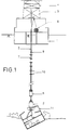
- Figure 1 shows the sectional device installed on board a drilling vessel (1).
- the device comprises the pincers (2) installed at the end of the rod train (3) and handled vertically by means of the derrick (4) and the rotation table (5).
- a control module (6) ensures the horizontal movement of the pincers by means of propellants and ensures its operation hydraulically.
- An umbilical (7) deployed by means of a winch (8) transmits energy and control to the desk pad module. It is attached along the rod train by means of quick-fixing collars (9).
- the ship (1) On the surface, the ship (1) is maintained by dynamic positioning in a circle with a radius of 5m.
- the pincers (2) are moved vertically by means of the rod train (3) and horizontally by means of the thrusters.
- the thrusters are oriented by direct rotation of the rod train (3) at the level of the rotation table (5).
- a damping device (10) composed of a series of circular plates is arranged at the lower part of the drill string so that the drill string cannot enter into compression during an abrupt release of the wreck (11 ) during a tear-off action. Indeed, an uncontrolled compression force risks damaging the rod train as a result of buckling of its section. The energy accumulated during the tensioning of the rod train is very important, because the extension of several meters under an effort of several hundred tonnes.
- FIG. 2 shows a section of the submarine module (6).
- a hydraulic pump (12) driven by an electric motor (13) supplies the motors of the propellants (14) and the jacks of the pincers via a set of solenoid valves (15) and a compensation tank (16).
- a "wide angle" camera (17) and a projector (18) allow the situation of the pincers (2) relative to the wreck (11) to be observed.
- the thrusters (14) are arranged diametrically opposite with respect to the rod train (3).
- the assembly is housed in a cylinder (19) made of very thick sheet metal, so as to protect the equipment during work inside the wreck (11).
- the rod train (3) passes through the module (6), as well as through the damping device (10).
- the diameter of the cylinder as well as that of the plates constituting the damping device (10) is such that it passes through the rotation table (5) during the handling phases on board.
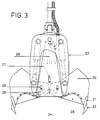
- Figure (3) shows a section of the pincers (2).
- the jaws (20) are fitted with lips (21) and teeth (22) which are highly dimensioned. They are, in known manner, actuated by means of jacks (23) and synchronized by means of gears (24).
- Removable walls (25) are bolted to the sides of the jaws (20), in order to transform them into pockets during the cargo recovery phase.
- the chassis has an interior volume of trapezoidal section (26) open at its lower part. This volume is arranged so as to protect a camera (27), two projectors (28) and a sounder (29).
- a device for injecting clear water makes it possible to form a cone of clear water in the fields of the camera (27) and is intended to increase the visibility when the pincers are at the bottom of the hold in a completely turbid volume of water due to the suspended sediment and the absence of current inside the wreck.
- This device must allow the identification of the objective when the pincers rest wide open on its teeth.
- Clear water is pumped to the surface by means of drilling pumps and is conveyed to the pincers through the rod train (3). It could just as easily be pumped at the level of the submarine module by means of a pump located inside the module for example.
- the method and the device of the invention are described in a preferred form, but not limiting. This is how the drilling vessel can be replaced by a naval support equipped with a derrick and a specific rod train.
- the thrusters fitted to the submarine module can be arranged in a different known manner, so as to move the pincers without the need to orient the rod train.
- the method and the device which are the subject of the invention apply to the recovery of all kinds of cargo, including radioactive products and nuclear reactors enclosed inside deep wrecks.
Landscapes
- Engineering & Computer Science (AREA)
- Mechanical Engineering (AREA)
- Ocean & Marine Engineering (AREA)
- Earth Drilling (AREA)
- Disintegrating Or Milling (AREA)
- Auxiliary Methods And Devices For Loading And Unloading (AREA)
- Physical Water Treatments (AREA)
- Confectionery (AREA)
- Ship Loading And Unloading (AREA)
- Organic Low-Molecular-Weight Compounds And Preparation Thereof (AREA)
Description
- La présente invention concerne un procédé de récupération d'une cargaison à bord d'une épave coulée par grande profondeur.
- Il existe au fond des mers de nombreuses épaves contenant des cargaisons de valeur qu'il est actuellement impossible d'exploiter par des procédés conventionnels du fait de la profondeur. En effet, les procédés actuels font appel le plus souvent à des plongeurs et sont par là même limités aux faibles profondeurs.
- La récupération d'une cargaison enfermée à l'intérieur d'une épave est une tâche très difficile. Elle nécessite que soit aménagé un accès au travers de l'épave. Cet accès peut se faire au travers des panneaux de cale, si la configuration le permet (épave reposant horizontalement sur le fond). Il peut se faire au travers de la coque, si l'épave est couchée ou renversée sur le fond.
- De façon courante, l'épave est découpée au moyen d'explosifs ou de chalumeaux oxycoupeurs mis en oeuvre par des plongeurs. Une fois que l'accès est aménagé, la cargaison est récupérée grâce à des moyens de levage conventionnels (bennes mises en oeuvre à partir de barges ancrées par exemple).
- C'est ainsi que des cargaisons de valeur ont pu être exploitées par des profondeurs inférieures à 500 m.
- Depuis quelques années, on utilise dans le domaine du sauvetage de très fortes bennes de dragage pour démolir les épaves qui présentent des dangers pour la navigation. Ces bennes sont actionnées par des câbles sous le contrôle de plongeurs. Leur force de fermeture et leur force de traction peut atteindre 500 Tonnes et permet alors d'extraire de gros morceaux d'épave par déchirement des tôles.
- En ce qui concerne les cargaisons profondes, seules les épaves présentant peu de difficultés d'accès ont pu être exploitées, soit que la cargaison gisait au fond par suite de rupture du navire lors du naufrage, soit que le navire était en bois et fortement détérioré. Des sous-marins habités ou télé-opérés ont été utilisés à cette fin avec succès.
- En ce qui concerne les cargaisons profondes enfermées à bord d'épaves contemporaines en acier, quelques tentatives ont été faites et aucun procédé ne s'est avéré techniquement et économiquement satisfaisant. Le démantèlement par explosifs a été associé à l'utilisation de bennes légères manutentionnées au moyen de câbles. L'efficacité des explosifs s'est avérée décevante par grande profondeur.
- Le procédé objet de l'invention permet de résoudre à la fois les problèmes de démantèlement de la coque et ceux de la récupération de la cargaison, et ce, par grande profondeur.
- Dans les années 70 a été développé le premier navire de forage à positionnement dynamique pour la recherche de pétrole par grande profondeur (300 m à 3000 m). Il existe actuellement dans le monde une quinzaine de navires capable de forer à grande profondeur. Ils sont équipés de derricks lourds capables de développer des efforts verticaux de 500 Tonnes. Des compensateurs de pilonnement permettent de compenser les mouvements du navire, lorsque l'outil est en contact avec le sol. La taille du puits situé en-dessous du derrick est telle (5mx5m) qu'il est possible de manutentionner des colis importants.
- L'objet de l'invention consiste à mettre en oeuvre une tenaille de forte capacité à partir de tels navires au moyen d'un module sous-marin chargé de la déplacer et de l'actionner sous le contrôle de caméras.
- L'invention concerne un procédé de récupération d'une cargaison enfermée à bord d'une épave coulée à grande profondeur, à partir d'un navire de forage à positionnement dynamique. Ce procédé est caractérisé par le fait que le démantèlement de l'épave est réalisé au moyen d'une tenaille et d'un dispositif amortisseur disposés à la partie inférieure du train de tige.
- L'invention concerne également un dispositif de démantèlement d'une épave coulée à grande profondeur, à partir d'un navire de forage à positionnement dynamique. Ce dispositif est caractérisé par le fait qu'il est constitué d'une tenaille et d'un dispositif amortisseur disposés à la partie inférieure du train de tige.
- La force de fermeture des mâchoires de la tenaille actionnées au moyen de vérins est telle (plusieurs centaines de Tonnes) qu'elles peuvent parvenir à déchirer les parois de l'épave afin d'accéder à la cargaison. Dans la phase de récupération, la tenaille est équipée de parois latérales et est utilisée à la manière d'une benne de plusieurs mètres cubes de capacité.
- Dans la phase de démolition, la tenaille est serrée puissamment sur la structure à démanteler. Elle est ensuite hissée verticalement de façon à arracher le morceau pris entre ses mâchoires. Les morceaux enlevés sont plus ou moins gros en fonction des lignes de déchirure obtenues. Certains morceaux résistent mieux que d'autres et il est parfois impossible de les arracher sans risquer la rupture du train de tige. La tenaille est alors déplacée légèrement et, en général, après plusieurs tentatives, l'arrachement se produit. Ce travail de destruction par arrachement après serrage est bien différent du travail de prélèvement des grappins conventionnels. Le dispositif amortisseur est indispensable pour mettre en oeuvre le procédé. En effet, aux grandes profondeurs, sous l'effort maximum de traction, l'allongement total du train de tige est d'environ 10m. L'énergie accumulée du système "masse-ressort" est telle que sans le dispositif amortisseur, l'ensemble du module et de la tenaille remonterait, lors de l'arrachage, avec une forte accélération, bien plus haut que la position d'équilibre. Cela entraînerait un flambement incontrôlé du train de tige avec un risque de rupture.
- Les temps de mise en oeuvre sont relativement longs (1 cycle montée-descente par jour à la profondeur de 3000 m), mais de telles opérations peuvent s'avérer économiquement rentables étant donnée la valeur de certaines cargaisons de minerai par exemple.
- Le dispositif permettant la mise en oeuvre du procédé est décrit ci-après en référence aux dessins annexés, dans lesquels :
- la figure 1 représente en coupe le dispositif selon l'invention ;
- la figure 2 représente en coupe le module sous-marin ;
- la figure 3 représente en coupe la tenaille.
- La figure 1 représente le dispositif en coupe installé à bord d'un navire de forage (1). Le dispositif comporte la tenaille (2) installée à l'extrémité du train de tige (3) et manutentionnée verticalement au moyen du derrick (4) et de la table de rotation (5). Un module de contrôle (6) assure le déplacement horizontal de la tenaille au moyen de propulseurs et assure son fonctionnement par voie hydraulique. Un ombilical (7) déployé au moyen d'un treuil (8) transmet énergie et contrôle au module sous-main. Il est attaché le long du train de tige au moyen de colliers de fixation rapide (9).
- A la surface, le navire (1) est maintenu par positionnement dynamique dans un cercle de rayon de 5m. Au fond, la tenaille (2) est déplacée verticalement au moyen du train de tige (3) et horizontalement au moyen des propulseurs. Dans une forme préférentielle de l'invention, les propulseurs sont orientés par rotation directe du train de tige (3) au niveau de la table de rotation (5).
- Un dispositif amortisseur (10) composé d'une série de plaques circulaires est disposé à la partie inférieure du train de tige de façon à ce que le train de tige ne puisse rentrer en compression lors d'un relâchement brusque de l'épave (11) pendant une action d'arrachement. En effet, un effort de compression non contrôlé risque de détériorer le train de tige par suite de flambement de sa section. L'énergie accumulée lors de la mise sous tension du train de tige est très importante, du fait de l'allongement de plusieurs mètres sous un effort de plusieurs centaines de tonnes.
- La figure 2 représente une coupe du module sous-marin (6). Une pompe hydraulique (12) entraînée par un moteur électrique (13) alimente les moteurs des propulseurs (14) et les vérins de la tenaille via un ensemble d'électrovannes (15) et un réservoir de compensation (16).
- A la base du module une caméra "grand angle" (17) et un projecteur (18) permettent d'observer la situation de la tenaille (2) par rapport à l'épave (11).
- A la partie supérieure, les propulseurs (14) sont disposés diamétralement opposés par rapport au train de tige (3).
- L'ensemble est logé dans un cylindre (19) réalisé en tôle de forte épaisseur, de façon à protéger les équipements lors du travail à l'intérieur de l'épave (11). Le train de tige (3) passe au travers du module (6), ainsi qu'au travers du dispositif amortisseur (10). Le diamètre du cylindre ainsi que celui des plaques constituant le dispositif amortisseur (10) est tel qu'il passe au travers de la table de rotation (5) lors des phases de manutention bord.
- La figure (3) représente une coupe de la tenaille (2). Les mâchoires (20) sont équipées de lèvres (21) et de dents (22) fortement dimensionnées. Elles sont, de façon connue, actionnées au moyen de vérins (23) et synchronisées au moyen d'engrenages (24). Des parois démontables (25) sont boulonnées sur les côtés des mâchoires (20), afin de les transformer en poches lors de la phase de récupération de la cargaison.
- Le châssis présente un volume intérieur de section trapézoïdale (26) ouvert à sa partie inférieure. Ce volume est agencé de façon à protéger une caméra (27), deux projecteurs (28) et un sondeur (29). Un dispositif d'injection d'eau claire permet de former un cône d'eau claire dans le champs de la caméra (27) et est destiné à accroître la visibilité lorsque la tenaille est à fond de cale dans un volume d'eau complètement turbide du fait du sédiment en suspension et de l'absence de courant a l'intérieur de l'épave.
- Ce dispositif doit permettre l'identification de l'objectif lorsque la tenaille repose grand ouverte sur ses dents.
- L'eau claire est pompée à la surface au moyen des pompes de forage et est conduite vers la tenaille au travers du train de tige (3). Elle pourrait tout aussi bien être pompée au niveau du module sous-marin au moyen d'une pompe située à l'intérieur du module par exemple.
- Le procédé et le dispositif de l'invention sont décrit dans une forme préférentielle, mais non limitative. C'est ainsi que le navire de forage peut être remplacé par un support naval équipé d'un derrick et d'un train de tige spécifique. Les propulseurs équipant le module sous-marin peuvent être disposés d'une manière différente connue, de façon à déplacer la tenaille sans qu'il soit nécessaire d'orienter le train de tige.
- Le procédé et le dispositif objet de l'invention s'appliquent à la récupération de toute sorte de cargaison y compris les produit radioactifs et réacteurs nucléaires enfermés à l'intérieur d'épaves profondes.
Claims (9)
- Procédé de récupération d'une cargaison enfermée à bord d'une épave coulée à grande profondeur, à partir d'un navire de forage à positionnement dynamique, caractérisé en ce que le démantèlement de l'épave est réalisé au moyen d'une tenaille (2) et d'un dispositif amortisseur (10) disposés à la partie inférieure du train de tige (3).
- Dispositif de démantèlement d'une épave à grande profondeur, à partir d'un navire de forage à positionnement dynamique, caractérisé en ce qu'il est constitué d'une tenaille (2) et d'un dispositif amortisseur (10) disposés à la partie inférieure du train de tige (3).
- Dispositif selon la revendication 2, caractérisé en ce que le dispositif amortisseur (10) est constitué d'une série de plaques circulaires perpendiculaires au train de tige (3).
- Dispositif selon la revendication 2, caractérisé en ce que, lors de la phase de récupération, la tenaille (2) est équipée de parois latérales (25).
- Dispositif selon les revendications 2 et 4, caractérisé en ce que le châssis de la tenaille comporte un volume de section trapézoïdale (26) ouvert à sa partie inférieure destiné à protéger un ensemble de caméra (27) et de projecteur (28).
- Dispositif selon la revendication 5, caractérisé en ce que de l'eau claire est injectée au travers de ce volume.
- Dispositif selon la revendication 2, caractérisé en ce que la tenaille est contrôlée par des propulseurs (14) disposés diamétralement opposés par rapport au train de tige à la partie supérieure d'un module sous-marin (6).
- Dispositif selon les revendications 2 et 7, caractérisé en ce les propulseurs (14) sont orientés directement au moyen du train de tige (3).
- Dispositif selon les revendications 2 et 7, caractérisé en ce le train de tige (3) passe au travers du système amortisseur (10) et du module sous-marin (6).
Applications Claiming Priority (3)
| Application Number | Priority Date | Filing Date | Title |
|---|---|---|---|
| FR9402753 | 1994-03-10 | ||
| FR9402753A FR2717148B1 (fr) | 1994-03-10 | 1994-03-10 | Procédé de récupération d'une cargaison à bord d'une épave. |
| PCT/FR1995/000268 WO1995024337A1 (fr) | 1994-03-10 | 1995-03-09 | Procede de recuperation d'une cargaison a bord d'une epave |
Publications (2)
| Publication Number | Publication Date |
|---|---|
| EP0749384A1 EP0749384A1 (fr) | 1996-12-27 |
| EP0749384B1 true EP0749384B1 (fr) | 1997-08-13 |
Family
ID=9460871
Family Applications (1)
| Application Number | Title | Priority Date | Filing Date |
|---|---|---|---|
| EP95911382A Expired - Lifetime EP0749384B1 (fr) | 1994-03-10 | 1995-03-09 | Procede de recuperation d'une cargaison a bord d'une epave |
Country Status (9)
| Country | Link |
|---|---|
| EP (1) | EP0749384B1 (fr) |
| JP (1) | JPH09509911A (fr) |
| AT (1) | ATE156764T1 (fr) |
| AU (1) | AU680741B2 (fr) |
| CA (1) | CA2184066A1 (fr) |
| DE (1) | DE69500562D1 (fr) |
| FR (1) | FR2717148B1 (fr) |
| NO (1) | NO963455L (fr) |
| WO (1) | WO1995024337A1 (fr) |
Cited By (1)
| Publication number | Priority date | Publication date | Assignee | Title |
|---|---|---|---|---|
| EP1054111A1 (fr) * | 1999-05-19 | 2000-11-22 | Boudewijn Gabriel Van Rompay | Méthode et installation pour réaliser des opérations sous-marines |
Families Citing this family (9)
| Publication number | Priority date | Publication date | Assignee | Title |
|---|---|---|---|---|
| FR2741037B1 (fr) * | 1995-11-10 | 1998-01-30 | Ifremer | Procede de recuperation d'une cargaison a bord d'une epave et panier de recuperation |
| EP1331191A1 (fr) * | 2002-01-25 | 2003-07-30 | IHC Gusto Engineering B.V. | Engin de levage flottant |
| FR2850631B1 (fr) * | 2003-01-31 | 2006-03-03 | Ifremer | Procede de recuperation d'une cargaison de liquides polluants a bord d'une epave |
| KR20120045858A (ko) | 2010-11-01 | 2012-05-09 | 대우조선해양 주식회사 | 극지용 시추선 |
| KR20120048097A (ko) * | 2010-11-05 | 2012-05-15 | 대우조선해양 주식회사 | 극지용 시추선 |
| CN102616349A (zh) * | 2011-01-27 | 2012-08-01 | 裘尧云 | 沉船水下破碎打捞法 |
| RU2521070C2 (ru) * | 2012-04-12 | 2014-06-27 | Евгений Игоревич Есаулов | Надводная платформа для поднятия и обработки грузов со дна акватории, в том числе опасных |
| WO2013176562A1 (fr) * | 2012-05-21 | 2013-11-28 | Esaulov Evgeny Igorevich | Plate-forme supra-aquatique destinée à remonter des objets à partir du fond d'une étendue d'eau et à traiter des charges, y compris des objets dangereux |
| CN107738733A (zh) * | 2017-09-19 | 2018-02-27 | 昆明理工大学 | 一种水下打捞机械手及其使用方法 |
Family Cites Families (3)
| Publication number | Priority date | Publication date | Assignee | Title |
|---|---|---|---|---|
| GB367567A (en) * | 1931-02-23 | 1932-02-25 | Ladislas Schill | An improved grapple for raising submarines and the like |
| US2355086A (en) * | 1943-10-27 | 1944-08-08 | Walter B Lang | Marine salvage device |
| US3843184A (en) * | 1972-07-12 | 1974-10-22 | E Horton | Underwater search and salvage system |
-
1994
- 1994-03-10 FR FR9402753A patent/FR2717148B1/fr not_active Expired - Fee Related
-
1995
- 1995-03-09 EP EP95911382A patent/EP0749384B1/fr not_active Expired - Lifetime
- 1995-03-09 DE DE69500562T patent/DE69500562D1/de not_active Expired - Lifetime
- 1995-03-09 JP JP7523270A patent/JPH09509911A/ja active Pending
- 1995-03-09 AU AU18967/95A patent/AU680741B2/en not_active Ceased
- 1995-03-09 WO PCT/FR1995/000268 patent/WO1995024337A1/fr not_active Ceased
- 1995-03-09 AT AT95911382T patent/ATE156764T1/de not_active IP Right Cessation
- 1995-03-09 CA CA002184066A patent/CA2184066A1/fr not_active Abandoned
-
1996
- 1996-08-20 NO NO963455A patent/NO963455L/no unknown
Cited By (3)
| Publication number | Priority date | Publication date | Assignee | Title |
|---|---|---|---|---|
| EP1054111A1 (fr) * | 1999-05-19 | 2000-11-22 | Boudewijn Gabriel Van Rompay | Méthode et installation pour réaliser des opérations sous-marines |
| BE1013045A3 (nl) * | 1999-05-19 | 2001-08-07 | Rompay Boudewijn Gabriel Van | Werkwijze en installatie voor het onder water uitvoeren van werkzaamheden met een kraan op een vastgezet ponton. |
| US6318284B1 (en) | 1999-05-19 | 2001-11-20 | VAN ROMPAY BOUDEWIJN GABRIëL | Method and installation for carrying out operations under water with a crane on a fixed pontoon |
Also Published As
| Publication number | Publication date |
|---|---|
| FR2717148A1 (fr) | 1995-09-15 |
| CA2184066A1 (fr) | 1995-09-14 |
| EP0749384A1 (fr) | 1996-12-27 |
| NO963455L (no) | 1996-08-20 |
| AU680741B2 (en) | 1997-08-07 |
| AU1896795A (en) | 1995-09-25 |
| FR2717148B1 (fr) | 1996-07-12 |
| WO1995024337A1 (fr) | 1995-09-14 |
| ATE156764T1 (de) | 1997-08-15 |
| DE69500562D1 (de) | 1997-09-18 |
| JPH09509911A (ja) | 1997-10-07 |
Similar Documents
| Publication | Publication Date | Title |
|---|---|---|
| NL1009277C2 (nl) | Werkwijze en inrichting voor het nauwkeurig plaatsen van relatief zware voorwerpen op en wegnemen van zware voorwerpen van de zeebodem. | |
| CN103781698B (zh) | 锚索张紧方法 | |
| EP3479052B1 (fr) | Procédé et dispositif d'élimination d'une pièce d'artillerie non explosée se trouvant sous l'eau | |
| WO1995024337A1 (fr) | Procede de recuperation d'une cargaison a bord d'une epave | |
| NL8301831A (nl) | Inrichting voor het lichten en verwijderen van het onderstel van een niet meer gebruikte offshore-constructie. | |
| US3654649A (en) | System for retrieving anchor chains | |
| WO2008116997A1 (fr) | Dispositif de decoupe et ouverture/fermeture d'un orifice dans une paroi au fond de la mer | |
| US6354765B2 (en) | Method of transporting and disposing of an offshore platform jacket | |
| US10633817B2 (en) | Removing submerged piles of offshore production platforms | |
| FR2660399A1 (fr) | Procede de pose de conduites tubulaires. | |
| US20230047236A1 (en) | Containment boom, system, and method for confining an oil spill | |
| EP1449763B1 (fr) | Procédé et installation de récupération d'effluents en mer à l'aide d'un réservoir navette | |
| EP0699804A1 (fr) | Appareil et méthode pour le cisaillage de tubes d'une structure en treillis, en particulier pour l'utilisation sous-marine | |
| US6061635A (en) | Seismic handling device | |
| KR20170055631A (ko) | 침몰 선박을 인양하는 방법 | |
| EP1648761B1 (fr) | Station sous-marine autonome | |
| GB2027781A (en) | Improvements in or Relating to Underwater Operations | |
| Culwell | Removal and disposal of deck and jacket structures | |
| US7296949B2 (en) | Removal of obsolete drill platforms from inland seas and ocean floors | |
| KR20210157231A (ko) | 포터블 앵커링 장치 | |
| US20260022636A1 (en) | Seabed mining system and method | |
| JP7624500B1 (ja) | 施工方法 | |
| NO346866B1 (en) | Containment boom, system, and method for confining an oil spill | |
| FR3031957A1 (fr) | Dispositif modulaire de demantelement d'epaves en mer profonde et de recuperation de cargaison | |
| WO2004069647A1 (fr) | Procede de recuperation d'une cargaison de liquides polluants a bord d'une epave |
Legal Events
| Date | Code | Title | Description |
|---|---|---|---|
| PUAI | Public reference made under article 153(3) epc to a published international application that has entered the european phase |
Free format text: ORIGINAL CODE: 0009012 |
|
| 17P | Request for examination filed |
Effective date: 19960909 |
|
| AK | Designated contracting states |
Kind code of ref document: A1 Designated state(s): AT BE CH DE DK ES FR GB GR IE IT LI LU MC NL PT SE |
|
| GRAG | Despatch of communication of intention to grant |
Free format text: ORIGINAL CODE: EPIDOS AGRA |
|
| GRAH | Despatch of communication of intention to grant a patent |
Free format text: ORIGINAL CODE: EPIDOS IGRA |
|
| 17Q | First examination report despatched |
Effective date: 19970115 |
|
| GRAH | Despatch of communication of intention to grant a patent |
Free format text: ORIGINAL CODE: EPIDOS IGRA |
|
| GRAA | (expected) grant |
Free format text: ORIGINAL CODE: 0009210 |
|
| AK | Designated contracting states |
Kind code of ref document: B1 Designated state(s): AT BE CH DE DK ES FR GB GR IE IT LI LU MC NL PT SE |
|
| PG25 | Lapsed in a contracting state [announced via postgrant information from national office to epo] |
Ref country code: NL Free format text: LAPSE BECAUSE OF FAILURE TO SUBMIT A TRANSLATION OF THE DESCRIPTION OR TO PAY THE FEE WITHIN THE PRESCRIBED TIME-LIMIT Effective date: 19970813 Ref country code: IT Free format text: LAPSE BECAUSE OF FAILURE TO SUBMIT A TRANSLATION OF THE DESCRIPTION OR TO PAY THE FEE WITHIN THE PRE;WARNING: LAPSES OF ITALIAN PATENTS WITH EFFECTIVE DATE BEFORE 2007 MAY HAVE OCCURRED AT ANY TIME BEFORE 2007. THE CORRECT EFFECTIVE DATE MAY BE DIFFERENT FROM THE ONE RECORDED.SCRIBED TIME-LIMIT Effective date: 19970813 Ref country code: GR Free format text: LAPSE BECAUSE OF FAILURE TO SUBMIT A TRANSLATION OF THE DESCRIPTION OR TO PAY THE FEE WITHIN THE PRESCRIBED TIME-LIMIT Effective date: 19970813 Ref country code: GB Free format text: LAPSE BECAUSE OF FAILURE TO SUBMIT A TRANSLATION OF THE DESCRIPTION OR TO PAY THE FEE WITHIN THE PRESCRIBED TIME-LIMIT Effective date: 19970813 Ref country code: FR Free format text: THE PATENT HAS BEEN ANNULLED BY A DECISION OF A NATIONAL AUTHORITY Effective date: 19970813 Ref country code: ES Free format text: THE PATENT HAS BEEN ANNULLED BY A DECISION OF A NATIONAL AUTHORITY Effective date: 19970813 Ref country code: DK Free format text: LAPSE BECAUSE OF NON-PAYMENT OF DUE FEES Effective date: 19970813 Ref country code: AT Effective date: 19970813 |
|
| REF | Corresponds to: |
Ref document number: 156764 Country of ref document: AT Date of ref document: 19970815 Kind code of ref document: T |
|
| REG | Reference to a national code |
Ref country code: CH Ref legal event code: EP |
|
| REF | Corresponds to: |
Ref document number: 69500562 Country of ref document: DE Date of ref document: 19970918 |
|
| PG25 | Lapsed in a contracting state [announced via postgrant information from national office to epo] |
Ref country code: SE Effective date: 19971113 |
|
| PG25 | Lapsed in a contracting state [announced via postgrant information from national office to epo] |
Ref country code: DE Effective date: 19971114 |
|
| PG25 | Lapsed in a contracting state [announced via postgrant information from national office to epo] |
Ref country code: PT Effective date: 19971118 |
|
| NLV1 | Nl: lapsed or annulled due to failure to fulfill the requirements of art. 29p and 29m of the patents act | ||
| GBV | Gb: ep patent (uk) treated as always having been void in accordance with gb section 77(7)/1977 [no translation filed] |
Effective date: 19970813 |
|
| PG25 | Lapsed in a contracting state [announced via postgrant information from national office to epo] |
Ref country code: LU Free format text: LAPSE BECAUSE OF NON-PAYMENT OF DUE FEES Effective date: 19980309 |
|
| PG25 | Lapsed in a contracting state [announced via postgrant information from national office to epo] |
Ref country code: BE Free format text: LAPSE BECAUSE OF NON-PAYMENT OF DUE FEES Effective date: 19980331 |
|
| PG25 | Lapsed in a contracting state [announced via postgrant information from national office to epo] |
Ref country code: IE Free format text: LAPSE BECAUSE OF NON-PAYMENT OF DUE FEES Effective date: 19980605 |
|
| PLBE | No opposition filed within time limit |
Free format text: ORIGINAL CODE: 0009261 |
|
| STAA | Information on the status of an ep patent application or granted ep patent |
Free format text: STATUS: NO OPPOSITION FILED WITHIN TIME LIMIT |
|
| REG | Reference to a national code |
Ref country code: IE Ref legal event code: FD4D Ref document number: 75879 Country of ref document: IE |
|
| 26N | No opposition filed | ||
| BERE | Be: lapsed |
Owner name: INSTITUT FRANCAIS DE RECHERCHE POUR L'EXPLOITATION Effective date: 19980331 |
|
| PG25 | Lapsed in a contracting state [announced via postgrant information from national office to epo] |
Ref country code: MC Free format text: LAPSE BECAUSE OF NON-PAYMENT OF DUE FEES Effective date: 19980930 |
|
| REG | Reference to a national code |
Ref country code: FR Ref legal event code: ST |
|
| PG25 | Lapsed in a contracting state [announced via postgrant information from national office to epo] |
Ref country code: LI Free format text: LAPSE BECAUSE OF NON-PAYMENT OF DUE FEES Effective date: 19990331 Ref country code: CH Free format text: LAPSE BECAUSE OF NON-PAYMENT OF DUE FEES Effective date: 19990331 |
|
| REG | Reference to a national code |
Ref country code: CH Ref legal event code: PL |