EP0748986B1 - Dispositif de commande centralisée d'un appareil à plusieurs foyers de chauffe - Google Patents
Dispositif de commande centralisée d'un appareil à plusieurs foyers de chauffe Download PDFInfo
- Publication number
- EP0748986B1 EP0748986B1 EP96401245A EP96401245A EP0748986B1 EP 0748986 B1 EP0748986 B1 EP 0748986B1 EP 96401245 A EP96401245 A EP 96401245A EP 96401245 A EP96401245 A EP 96401245A EP 0748986 B1 EP0748986 B1 EP 0748986B1
- Authority
- EP
- European Patent Office
- Prior art keywords
- ring
- button
- push
- push button
- sectors
- Prior art date
- Legal status (The legal status is an assumption and is not a legal conclusion. Google has not performed a legal analysis and makes no representation as to the accuracy of the status listed.)
- Expired - Lifetime
Links
- 238000010411 cooking Methods 0.000 title claims description 4
- 230000005693 optoelectronics Effects 0.000 claims description 8
- 238000012800 visualization Methods 0.000 claims description 5
- 238000010438 heat treatment Methods 0.000 claims description 3
- 238000010304 firing Methods 0.000 claims 8
- 238000009304 pastoral farming Methods 0.000 claims 1
- 238000000034 method Methods 0.000 description 2
- 206010000496 acne Diseases 0.000 description 1
- 230000008033 biological extinction Effects 0.000 description 1
- 238000010891 electric arc Methods 0.000 description 1
Images

Classifications
-
- F—MECHANICAL ENGINEERING; LIGHTING; HEATING; WEAPONS; BLASTING
- F24—HEATING; RANGES; VENTILATING
- F24C—DOMESTIC STOVES OR RANGES ; DETAILS OF DOMESTIC STOVES OR RANGES, OF GENERAL APPLICATION
- F24C3/00—Stoves or ranges for gaseous fuels
- F24C3/12—Arrangement or mounting of control or safety devices
- F24C3/124—Control panels
Definitions
- the main subject of the present invention is a centralized control device for a several heaters.
- buttons or knobs are provided to control the ignition and the burner operation, adjusting the power of these burners, and their shutdown.
- a command button is provided for each burner on the stove or the hob cooking so that handling errors pimples are often common and the cost of parts multiple to predict and their mounting is notable.
- the present invention therefore aims to fill this gap.
- the invention relates to a device for centralized control of an appliance with several homes for heating, such as for example gas burners a stove or hob, characterized by a unique and compact element which is integral with the device and basically consists of a push button divided into as many sectors as households to control the starting and stopping of said hearths, and a crown, or first crown, concentric with the push button to control the power adjustment of the fireplaces.
- This device is further characterized by a second crown concentric with the first and showing the power of each household.
- the second crown is divided into sectors of visualization corresponding respectively to the sectors of the push button.
- Each sector of the push button has advantageously a touch button for select the appliance focus corresponding to this sector.
- a contactor for example of the type optoelectronics, is associated with the push button for control the starting and stopping of the fireplaces.
- This device is further characterized in that between the push button and first crown externally concentric with this push button, is interposed a guide ring in translation of the sectors of the push button and guiding in rotation of said first crowned.
- This first crown has a disc constituting a contactor for example of the type optoelectronics, which simultaneously controls the setting in power of the selected focus and visualization of the power level on the second crown.
- the second crown and each sector of the push button are fitted with light emitting diodes.
- the first crown mounted to rotate free around the sectors of the push button is provided a notch cooperating with an element, such as a ball, integral with the housing containing the device, and constantly requested in the direction of this notch.
- the push button is stressed by a spring arranged between the sectors constituting this push button and the guide ring cited above.
- the push button cooperates with an anti-rotation lug integral with the push button guide ring and of the first crown.
- Figure 1 is a partial perspective view of the upper part of a cooker fitted with a centralized control device according to this invention.
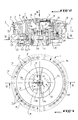
- Figure 2 is an axial sectional view of this device, made along line II-II of the figure 3.
- Figure 3 is a top plan view of this control device, according to arrow III of the figure 2.
- Figure 4 is a sectional view made substantially along line IV-IV of Figure 2.
- FIG. 1 a gas stove whose plate upper 6 is equipped with three gas burners 1, 2, 3 and a centralized control device D of the three burners, in accordance with the present invention.
- the device D could be provided in one another place on the stove, and it could control a lower number of gas burners or greater than three.
- the device D could just as easily command electric hot plates or a set mixed gas burners and hot plates electric, as is currently the case.
- the device D consists of a unique and compact element with a shape curved circular, as can be seen on the figures. It is integral with a housing consisting of several elements identified at 4 in FIG. 2, and fixed for example with screws 5 on the plate upper 6 of the stove.
- This device D essentially consists of a push button 7 divided into as many sectors identified in 7a, 7b, 7c than burners 1, 2, 3, i.e. three sectors, according to the embodiment shown. Each sector belonging to push button 7 will allow the start and stop of one of the gas burners, as will be described in more detail far.
- a crown, or first crown 8 is arranged with externally concentric with the push button 7, as can be seen in Figures 2 and 3, this crown being rotatably mounted in the housing 4 and being hand-operated to allow adjustment of the gas burners 1, 2 and 3.
- a second crown 9, externally concentric with the first ring 8 allows the visualization of the power level of each burner, which level of power is controlled by said first crown 8.
- the second crown 9 is divided into three corresponding viewing sectors 9a, 9b, 9c respectively to sectors 7a, 7b, 7c of the push button 7.
- This second crown 9 is composed precisely a transparent ring marked at 10 on the FIG. 2 and under which are arranged in an arc, light emitting diodes 11 mounted in the housing 4.
- each sector 7a, 7b, 7c housed in a body 40 forming with said sectors the push button 7, has a button to touch 12 to select the burner to gas corresponding to this sector, as will be described in more detail later.
- Each sector 7a, 7b, 7c of push button 7 is equipped with diodes electroluminescent marked schematically in 13a, 13b and 13c in Figure 3.
- a contactor 14 is associated with push button 7 with sectors 7a, 7b, 7c for control the starting or stopping of the burners at gas 1, 2, 3. More specifically, and according to an example of embodiment, the contactor 14 is of the type optoelectronics, i.e. consists essentially a blade 15 projecting from a support 16 for the flush buttons 12 and susceptible, under the action of sectors 7a, 7b, 7c of push button 7, to enter or to extract of a U-shaped piece 17 secured to the housing 4 at screw means 18 for example.
- This ring 20 allows guiding in translation vertical of the sectors 7a, 7b, 7c of the push button 7, as well as the guiding in rotation of the first crown 8 around the push button 7.
- the first crown 8 is provided at its lower part and inside the housing 4 of a contactor 21 which can also be of the optoelectronic type. More specifically, this contactor 21 consists of a disc 22 fixed by screws 23 on the first ring 8 and formed of a multiplicity of slots 24 clearly visible on the Figure 4. The periphery of the disc 22 with the slots 24 rotates inside a U-shaped part 25 secured to the housing 4 (see Figure 2), so that the beam of the optoelectronic system will be interrupted alternately.
- the contactor 21 which comes to be described will, by hand rotation of the first crown 8, simultaneous control of the adjustment of the selected gas burner and the display of the selected power level, on the second crown 9.
- a spring has been shown at 29 in FIGS. 2 and 4 arranged between the push button 7 and the ring guide 20, this spring 29 constantly urging the push button 7 upwards, as visible on the figure 2.
- the device which has just been described constitutes a centralized but selective and reliable control of the three gas burners 1, 2, 3 via a circuit electronic with program that doesn't need to be described and which is not part of this invention.
- sector 7a of the push button 7 which has the effect of opening the arrival of gas, to trigger the electric arc of the burner spark plug (not shown) selected, and to light all the diodes light emitting 11 of sector 9a of the second crown 9 simultaneously.
- the arc formed by the diodes light-emitting 11 of the display sector 9a will be lit over a greater or lesser length, according to the gas flow chosen by rotation of the crown 8.
- a second burner for example the burner 1, just operate as explained previously, by first touching key 12 of sector 7b of push button 7, and by pressing then on this sector while the diode light emitting 13b will be on.
Landscapes
- Engineering & Computer Science (AREA)
- Combustion & Propulsion (AREA)
- Mechanical Engineering (AREA)
- General Engineering & Computer Science (AREA)
- Chemical & Material Sciences (AREA)
- Feeding And Controlling Fuel (AREA)
- Regulation And Control Of Combustion (AREA)
- Control Of Resistance Heating (AREA)
- Cookers (AREA)
- Measurement And Recording Of Electrical Phenomena And Electrical Characteristics Of The Living Body (AREA)
- Selective Calling Equipment (AREA)
- Commercial Cooking Devices (AREA)
- General Preparation And Processing Of Foods (AREA)
Applications Claiming Priority (2)
| Application Number | Priority Date | Filing Date | Title |
|---|---|---|---|
| FR9506924A FR2735215B1 (fr) | 1995-06-12 | 1995-06-12 | Dispositif de commande centralisee d'un appareil a plusieurs foyers de chauffe |
| FR9506924 | 1995-06-12 |
Publications (2)
| Publication Number | Publication Date |
|---|---|
| EP0748986A1 EP0748986A1 (fr) | 1996-12-18 |
| EP0748986B1 true EP0748986B1 (fr) | 1999-09-01 |
Family
ID=9479866
Family Applications (1)
| Application Number | Title | Priority Date | Filing Date |
|---|---|---|---|
| EP96401245A Expired - Lifetime EP0748986B1 (fr) | 1995-06-12 | 1996-06-10 | Dispositif de commande centralisée d'un appareil à plusieurs foyers de chauffe |
Country Status (7)
| Country | Link |
|---|---|
| EP (1) | EP0748986B1 (da) |
| AT (1) | ATE184093T1 (da) |
| DE (1) | DE69604022T2 (da) |
| DK (1) | DK0748986T3 (da) |
| ES (1) | ES2138302T3 (da) |
| FR (1) | FR2735215B1 (da) |
| GR (1) | GR3031986T3 (da) |
Families Citing this family (1)
| Publication number | Priority date | Publication date | Assignee | Title |
|---|---|---|---|---|
| EP4271941A4 (en) * | 2020-12-03 | 2025-01-08 | Femas Metal San. Ve Tic. A.S. | OVEN WITH SINGLE BUTTON CONTROL DEVICE |
Family Cites Families (2)
| Publication number | Priority date | Publication date | Assignee | Title |
|---|---|---|---|---|
| FR2462663A1 (fr) * | 1979-07-26 | 1981-02-13 | Dietrich & Cie De | Appareil de cuisson, notamment table de cuisson encastrable |
| DE4319170C1 (de) * | 1993-06-09 | 1994-09-01 | Gaggenau Werke | Bedienungs- und Anzeigeeinheit für eine Kochfeldplatte |
-
1995
- 1995-06-12 FR FR9506924A patent/FR2735215B1/fr not_active Expired - Fee Related
-
1996
- 1996-06-10 ES ES96401245T patent/ES2138302T3/es not_active Expired - Lifetime
- 1996-06-10 AT AT96401245T patent/ATE184093T1/de not_active IP Right Cessation
- 1996-06-10 DK DK96401245T patent/DK0748986T3/da active
- 1996-06-10 DE DE69604022T patent/DE69604022T2/de not_active Expired - Fee Related
- 1996-06-10 EP EP96401245A patent/EP0748986B1/fr not_active Expired - Lifetime
-
1999
- 1999-11-29 GR GR990403079T patent/GR3031986T3/el unknown
Also Published As
| Publication number | Publication date |
|---|---|
| DE69604022D1 (de) | 1999-10-07 |
| EP0748986A1 (fr) | 1996-12-18 |
| DE69604022T2 (de) | 2000-02-24 |
| DK0748986T3 (da) | 2000-04-03 |
| ATE184093T1 (de) | 1999-09-15 |
| GR3031986T3 (en) | 2000-03-31 |
| FR2735215A1 (fr) | 1996-12-13 |
| ES2138302T3 (es) | 2000-01-01 |
| FR2735215B1 (fr) | 1997-09-05 |
Similar Documents
| Publication | Publication Date | Title |
|---|---|---|
| EP2551600B1 (fr) | Table de cuisson et procédé de commande en fonctionnement d'une table de cuisson | |
| EP2166290B1 (fr) | Procédé de commande d'une table de cuisson | |
| FR2658591A1 (fr) | Projet de commande des foyers de chauffage d'un appareil de cuisson, par touches sensitives. | |
| EP2265087A2 (fr) | Table de cuisson à plusieurs foyers de cuisson indèpendants | |
| EP0748986B1 (fr) | Dispositif de commande centralisée d'un appareil à plusieurs foyers de chauffe | |
| FR2970837A1 (fr) | Procede d'optimisation de positionnement d'au moins un recipient dispose au-dessus d'un ensemble d'inducteurs d'une table de cuisson a induction et table de cuisson a induction associee | |
| EP3312862B1 (fr) | Dispositif de commande manuelle pour un appareil electromenager | |
| FR2604510A1 (fr) | Cuisiniere a gaz comportant un bruleur de cuisson situe au-dessous d'une plaque de vitrocerame | |
| EP0751352A1 (fr) | Appareil de cuisson à brûleur centré sur un injecteur | |
| EP0939279A1 (fr) | Dispositif de surveillance et de sécurité pour appareil de cuisson ou de chauffage à gaz | |
| WO2021053019A1 (fr) | Foyer artificiel | |
| FR2708087A1 (fr) | Dispositif d'allumage intégré pour appareil à gaz. | |
| FR2910599A1 (fr) | Procede de verrouillage de moyens de commande des foyers d'une table de cuisson | |
| FR2789479A3 (fr) | Plaque de cuisson a gaz | |
| EP2552023B1 (fr) | Dispositif de commande d'un appareil électroménager comprenant un commutateur optique à touche tactile | |
| FR2682742A1 (fr) | Table de cuisson vitro-ceramique, chauffee au gaz. | |
| FR2998041A1 (fr) | Table de cuisson comprenant un clavier de commande | |
| FR2623885A1 (fr) | Table de cuisson | |
| EP1675435B2 (fr) | Procédé de commande d'une table de cuisson et table de cuisson associée | |
| EP0378460B1 (fr) | Mécanisme de commande pour régulation de puissance d'un appareil de cuisson et appareil de cuisson comportant un tel mécanisme | |
| FR2847660A1 (fr) | Dispositif de chauffage a bruleurs a gaz | |
| FR2933840A1 (fr) | Procede de commande d'au moins un moyen de chauffage d'un appareil de cuisson | |
| EP3312858A1 (fr) | Dispositif de commande manuelle pour un appareil électroménager | |
| FR2686148A1 (fr) | Dispositif de visualisation de l'intensite de la flamme d'un foyer a gaz. | |
| FR2939496A1 (fr) | Ensemble forme par une table de cuisson encastrable et un plan de travail comprenant au moins un dispositif d'eclairage |
Legal Events
| Date | Code | Title | Description |
|---|---|---|---|
| PUAI | Public reference made under article 153(3) epc to a published international application that has entered the european phase |
Free format text: ORIGINAL CODE: 0009012 |
|
| AK | Designated contracting states |
Kind code of ref document: A1 Designated state(s): AT BE CH DE DK ES FI GB GR IE IT LI LU MC NL PT SE |
|
| 17P | Request for examination filed |
Effective date: 19970329 |
|
| GRAG | Despatch of communication of intention to grant |
Free format text: ORIGINAL CODE: EPIDOS AGRA |
|
| GRAG | Despatch of communication of intention to grant |
Free format text: ORIGINAL CODE: EPIDOS AGRA |
|
| GRAH | Despatch of communication of intention to grant a patent |
Free format text: ORIGINAL CODE: EPIDOS IGRA |
|
| 17Q | First examination report despatched |
Effective date: 19981202 |
|
| GRAH | Despatch of communication of intention to grant a patent |
Free format text: ORIGINAL CODE: EPIDOS IGRA |
|
| GRAA | (expected) grant |
Free format text: ORIGINAL CODE: 0009210 |
|
| AK | Designated contracting states |
Kind code of ref document: B1 Designated state(s): AT BE CH DE DK ES FI GB GR IE IT LI LU MC NL PT SE |
|
| REF | Corresponds to: |
Ref document number: 184093 Country of ref document: AT Date of ref document: 19990915 Kind code of ref document: T |
|
| REG | Reference to a national code |
Ref country code: CH Ref legal event code: EP |
|
| REF | Corresponds to: |
Ref document number: 69604022 Country of ref document: DE Date of ref document: 19991007 |
|
| REG | Reference to a national code |
Ref country code: IE Ref legal event code: FG4D Free format text: FRENCH |
|
| ITF | It: translation for a ep patent filed | ||
| REG | Reference to a national code |
Ref country code: CH Ref legal event code: NV Representative=s name: TROESCH SCHEIDEGGER WERNER AG |
|
| GBT | Gb: translation of ep patent filed (gb section 77(6)(a)/1977) |
Effective date: 19991110 |
|
| REG | Reference to a national code |
Ref country code: ES Ref legal event code: FG2A Ref document number: 2138302 Country of ref document: ES Kind code of ref document: T3 |
|
| REG | Reference to a national code |
Ref country code: PT Ref legal event code: SC4A Free format text: AVAILABILITY OF NATIONAL TRANSLATION Effective date: 19991117 |
|
| REG | Reference to a national code |
Ref country code: DK Ref legal event code: T3 |
|
| PLBE | No opposition filed within time limit |
Free format text: ORIGINAL CODE: 0009261 |
|
| STAA | Information on the status of an ep patent application or granted ep patent |
Free format text: STATUS: NO OPPOSITION FILED WITHIN TIME LIMIT |
|
| 26N | No opposition filed | ||
| REG | Reference to a national code |
Ref country code: GB Ref legal event code: IF02 |
|
| PGFP | Annual fee paid to national office [announced via postgrant information from national office to epo] |
Ref country code: AT Payment date: 20050524 Year of fee payment: 10 |
|
| PGFP | Annual fee paid to national office [announced via postgrant information from national office to epo] |
Ref country code: FI Payment date: 20050525 Year of fee payment: 10 |
|
| PGFP | Annual fee paid to national office [announced via postgrant information from national office to epo] |
Ref country code: MC Payment date: 20050526 Year of fee payment: 10 Ref country code: DK Payment date: 20050526 Year of fee payment: 10 Ref country code: CH Payment date: 20050526 Year of fee payment: 10 |
|
| PGFP | Annual fee paid to national office [announced via postgrant information from national office to epo] |
Ref country code: SE Payment date: 20050527 Year of fee payment: 10 Ref country code: GB Payment date: 20050527 Year of fee payment: 10 Ref country code: DE Payment date: 20050527 Year of fee payment: 10 |
|
| PGFP | Annual fee paid to national office [announced via postgrant information from national office to epo] |
Ref country code: PT Payment date: 20050530 Year of fee payment: 10 Ref country code: NL Payment date: 20050530 Year of fee payment: 10 |
|
| PGFP | Annual fee paid to national office [announced via postgrant information from national office to epo] |
Ref country code: BE Payment date: 20050601 Year of fee payment: 10 |
|
| PGFP | Annual fee paid to national office [announced via postgrant information from national office to epo] |
Ref country code: LU Payment date: 20050603 Year of fee payment: 10 |
|
| PGFP | Annual fee paid to national office [announced via postgrant information from national office to epo] |
Ref country code: IE Payment date: 20050609 Year of fee payment: 10 |
|
| PGFP | Annual fee paid to national office [announced via postgrant information from national office to epo] |
Ref country code: GR Payment date: 20050610 Year of fee payment: 10 |
|
| PG25 | Lapsed in a contracting state [announced via postgrant information from national office to epo] |
Ref country code: GB Free format text: LAPSE BECAUSE OF NON-PAYMENT OF DUE FEES Effective date: 20060610 Ref country code: FI Free format text: LAPSE BECAUSE OF NON-PAYMENT OF DUE FEES Effective date: 20060610 Ref country code: AT Free format text: LAPSE BECAUSE OF NON-PAYMENT OF DUE FEES Effective date: 20060610 |
|
| PG25 | Lapsed in a contracting state [announced via postgrant information from national office to epo] |
Ref country code: SE Free format text: LAPSE BECAUSE OF NON-PAYMENT OF DUE FEES Effective date: 20060611 |
|
| PG25 | Lapsed in a contracting state [announced via postgrant information from national office to epo] |
Ref country code: IE Free format text: LAPSE BECAUSE OF NON-PAYMENT OF DUE FEES Effective date: 20060612 |
|
| PG25 | Lapsed in a contracting state [announced via postgrant information from national office to epo] |
Ref country code: MC Free format text: LAPSE BECAUSE OF NON-PAYMENT OF DUE FEES Effective date: 20060630 Ref country code: LI Free format text: LAPSE BECAUSE OF NON-PAYMENT OF DUE FEES Effective date: 20060630 Ref country code: DK Free format text: LAPSE BECAUSE OF NON-PAYMENT OF DUE FEES Effective date: 20060630 Ref country code: CH Free format text: LAPSE BECAUSE OF NON-PAYMENT OF DUE FEES Effective date: 20060630 Ref country code: BE Free format text: LAPSE BECAUSE OF NON-PAYMENT OF DUE FEES Effective date: 20060630 |
|
| PG25 | Lapsed in a contracting state [announced via postgrant information from national office to epo] |
Ref country code: PT Free format text: LAPSE BECAUSE OF NON-PAYMENT OF DUE FEES Effective date: 20061211 |
|
| PG25 | Lapsed in a contracting state [announced via postgrant information from national office to epo] |
Ref country code: NL Free format text: LAPSE BECAUSE OF NON-PAYMENT OF DUE FEES Effective date: 20070101 |
|
| PG25 | Lapsed in a contracting state [announced via postgrant information from national office to epo] |
Ref country code: DE Free format text: LAPSE BECAUSE OF NON-PAYMENT OF DUE FEES Effective date: 20070103 |
|
| REG | Reference to a national code |
Ref country code: DK Ref legal event code: EBP |
|
| REG | Reference to a national code |
Ref country code: PT Ref legal event code: MM4A Free format text: LAPSE DUE TO NON-PAYMENT OF FEES Effective date: 20061211 |
|
| REG | Reference to a national code |
Ref country code: CH Ref legal event code: PL |
|
| EUG | Se: european patent has lapsed | ||
| GBPC | Gb: european patent ceased through non-payment of renewal fee |
Effective date: 20060610 |
|
| NLV4 | Nl: lapsed or anulled due to non-payment of the annual fee |
Effective date: 20070101 |
|
| REG | Reference to a national code |
Ref country code: IE Ref legal event code: MM4A |
|
| BERE | Be: lapsed |
Owner name: *GAZ DE FRANCE Effective date: 20060630 |
|
| PG25 | Lapsed in a contracting state [announced via postgrant information from national office to epo] |
Ref country code: LU Free format text: LAPSE BECAUSE OF NON-PAYMENT OF DUE FEES Effective date: 20060610 |
|
| PG25 | Lapsed in a contracting state [announced via postgrant information from national office to epo] |
Ref country code: GR Free format text: LAPSE BECAUSE OF NON-PAYMENT OF DUE FEES Effective date: 20070104 |
|
| REG | Reference to a national code |
Ref country code: ES Ref legal event code: PC2A Owner name: GDF SUEZ Effective date: 20110616 |
|
| PGFP | Annual fee paid to national office [announced via postgrant information from national office to epo] |
Ref country code: IT Payment date: 20120526 Year of fee payment: 17 |
|
| PGFP | Annual fee paid to national office [announced via postgrant information from national office to epo] |
Ref country code: ES Payment date: 20120614 Year of fee payment: 17 |
|
| PG25 | Lapsed in a contracting state [announced via postgrant information from national office to epo] |
Ref country code: IT Free format text: LAPSE BECAUSE OF NON-PAYMENT OF DUE FEES Effective date: 20130610 |
|
| REG | Reference to a national code |
Ref country code: ES Ref legal event code: FD2A Effective date: 20140708 |
|
| PG25 | Lapsed in a contracting state [announced via postgrant information from national office to epo] |
Ref country code: ES Free format text: LAPSE BECAUSE OF NON-PAYMENT OF DUE FEES Effective date: 20130611 |