EP0748954B1 - Variable interconnecting transmission - Google Patents
Variable interconnecting transmission Download PDFInfo
- Publication number
- EP0748954B1 EP0748954B1 EP96109102A EP96109102A EP0748954B1 EP 0748954 B1 EP0748954 B1 EP 0748954B1 EP 96109102 A EP96109102 A EP 96109102A EP 96109102 A EP96109102 A EP 96109102A EP 0748954 B1 EP0748954 B1 EP 0748954B1
- Authority
- EP
- European Patent Office
- Prior art keywords
- output
- input
- shaft
- adjusting coupling
- transmission according
- Prior art date
- Legal status (The legal status is an assumption and is not a legal conclusion. Google has not performed a legal analysis and makes no representation as to the accuracy of the status listed.)
- Expired - Lifetime
Links
Images


Classifications
-
- F—MECHANICAL ENGINEERING; LIGHTING; HEATING; WEAPONS; BLASTING
- F16—ENGINEERING ELEMENTS AND UNITS; GENERAL MEASURES FOR PRODUCING AND MAINTAINING EFFECTIVE FUNCTIONING OF MACHINES OR INSTALLATIONS; THERMAL INSULATION IN GENERAL
- F16H—GEARING
- F16H37/00—Combinations of mechanical gearings, not provided for in groups F16H1/00 - F16H35/00
- F16H37/02—Combinations of mechanical gearings, not provided for in groups F16H1/00 - F16H35/00 comprising essentially only toothed or friction gearings
- F16H37/06—Combinations of mechanical gearings, not provided for in groups F16H1/00 - F16H35/00 comprising essentially only toothed or friction gearings with a plurality of driving or driven shafts; with arrangements for dividing torque between two or more intermediate shafts
- F16H37/08—Combinations of mechanical gearings, not provided for in groups F16H1/00 - F16H35/00 comprising essentially only toothed or friction gearings with a plurality of driving or driven shafts; with arrangements for dividing torque between two or more intermediate shafts with differential gearing
- F16H37/0833—Combinations of mechanical gearings, not provided for in groups F16H1/00 - F16H35/00 comprising essentially only toothed or friction gearings with a plurality of driving or driven shafts; with arrangements for dividing torque between two or more intermediate shafts with differential gearing with arrangements for dividing torque between two or more intermediate shafts, i.e. with two or more internal power paths
- F16H37/084—Combinations of mechanical gearings, not provided for in groups F16H1/00 - F16H35/00 comprising essentially only toothed or friction gearings with a plurality of driving or driven shafts; with arrangements for dividing torque between two or more intermediate shafts with differential gearing with arrangements for dividing torque between two or more intermediate shafts, i.e. with two or more internal power paths at least one power path being a continuously variable transmission, i.e. CVT
- F16H37/0846—CVT using endless flexible members
-
- F—MECHANICAL ENGINEERING; LIGHTING; HEATING; WEAPONS; BLASTING
- F16—ENGINEERING ELEMENTS AND UNITS; GENERAL MEASURES FOR PRODUCING AND MAINTAINING EFFECTIVE FUNCTIONING OF MACHINES OR INSTALLATIONS; THERMAL INSULATION IN GENERAL
- F16H—GEARING
- F16H9/00—Gearings for conveying rotary motion with variable gear ratio, or for reversing rotary motion, by endless flexible members
- F16H9/02—Gearings for conveying rotary motion with variable gear ratio, or for reversing rotary motion, by endless flexible members without members having orbital motion
- F16H9/04—Gearings for conveying rotary motion with variable gear ratio, or for reversing rotary motion, by endless flexible members without members having orbital motion using belts, V-belts, or ropes
- F16H9/12—Gearings for conveying rotary motion with variable gear ratio, or for reversing rotary motion, by endless flexible members without members having orbital motion using belts, V-belts, or ropes engaging a pulley built-up out of relatively axially-adjustable parts in which the belt engages the opposite flanges of the pulley directly without interposed belt-supporting members
- F16H9/16—Gearings for conveying rotary motion with variable gear ratio, or for reversing rotary motion, by endless flexible members without members having orbital motion using belts, V-belts, or ropes engaging a pulley built-up out of relatively axially-adjustable parts in which the belt engages the opposite flanges of the pulley directly without interposed belt-supporting members using two pulleys, both built-up out of adjustable conical parts
- F16H2009/163—Arrangements of two or more belt gearings mounted in parallel, e.g. for increasing transmittable torque
-
- F—MECHANICAL ENGINEERING; LIGHTING; HEATING; WEAPONS; BLASTING
- F16—ENGINEERING ELEMENTS AND UNITS; GENERAL MEASURES FOR PRODUCING AND MAINTAINING EFFECTIVE FUNCTIONING OF MACHINES OR INSTALLATIONS; THERMAL INSULATION IN GENERAL
- F16H—GEARING
- F16H37/00—Combinations of mechanical gearings, not provided for in groups F16H1/00 - F16H35/00
- F16H37/02—Combinations of mechanical gearings, not provided for in groups F16H1/00 - F16H35/00 comprising essentially only toothed or friction gearings
- F16H37/06—Combinations of mechanical gearings, not provided for in groups F16H1/00 - F16H35/00 comprising essentially only toothed or friction gearings with a plurality of driving or driven shafts; with arrangements for dividing torque between two or more intermediate shafts
- F16H37/08—Combinations of mechanical gearings, not provided for in groups F16H1/00 - F16H35/00 comprising essentially only toothed or friction gearings with a plurality of driving or driven shafts; with arrangements for dividing torque between two or more intermediate shafts with differential gearing
- F16H37/0833—Combinations of mechanical gearings, not provided for in groups F16H1/00 - F16H35/00 comprising essentially only toothed or friction gearings with a plurality of driving or driven shafts; with arrangements for dividing torque between two or more intermediate shafts with differential gearing with arrangements for dividing torque between two or more intermediate shafts, i.e. with two or more internal power paths
- F16H37/084—Combinations of mechanical gearings, not provided for in groups F16H1/00 - F16H35/00 comprising essentially only toothed or friction gearings with a plurality of driving or driven shafts; with arrangements for dividing torque between two or more intermediate shafts with differential gearing with arrangements for dividing torque between two or more intermediate shafts, i.e. with two or more internal power paths at least one power path being a continuously variable transmission, i.e. CVT
- F16H2037/088—Power split variators with summing differentials, with the input of the CVT connected or connectable to the input shaft
Definitions
- the invention relates to an adjusting coupling transmission with the features according to the preamble of claim 1.
- the invention further relates to an adjusting coupling gear the features according to the preamble of claim 2.
- the input power can in the first branch directly onto the planet gear and in the other branch via the continuously adjustable Transfer actuator to the ring gear of the planetary gear become.
- the output of the actuating coupling gear then forms that Sun gear or the sun gear shaft of the planetary gear.
- the invention is based on the object of actuating coupling gears of the type mentioned at the outset, that while maintaining the benefits achievable with it (large translation range, possibility of reversing the direction of rotation, low-loss operation in the most common operating modes in practice, stepless variation of the output speed below Load, high efficiency and cost-effective production) Construction is achieved in which impermissibly high speeds avoided become.
- a planetary sum gear is thus used in the the input power is divided into two power paths. While the first power path e.g. over a non-rotatable attached to the input shaft attached variator, which the Force on a wide V-belt transmits the transmission, the second power share is over a constant drive with a fixed ratio in the transmission headed. It is preferred if the variator is a belt transmission with adjustable pulleys, which is more preferred is driven directly by the input shaft. If the Constant drive is a belt drive with fixed pulleys, can have both an adjustable and a fixed pulley each be arranged in a rotationally fixed manner on the input shaft.
- the couplings are operable, preferably by the couplings in the transition point between two ranges of the output speed or when starting can be operated alternatively.
- the second Area bridges the planetary sum gear while at a second variant, the planetary sum gear in the second Area revolves as a closed block.
- the output speeds can be divided into two areas, namely in a power-split and a non-power split Area.
- the two areas are linked by the two couplings, where both clutches at the same speed of the first and of the second area are switchable under load.
- the second Coupling couples the variable power path via the variator, the first clutch couples the constant power path.
- both clutches can also be used for a short time be switched.
- By loosening one or the other Clutch can be under load and without between the two areas Traction interruption can be switched back and forth.
- Another advantage is that the couplings can be designed as positive couplings, so in a relatively simple and inexpensive design.
- both clutches are open, and the Variator is automatically controlled so that the gearbox output speed Is zero. Then the first clutch for the Constant drive closed and the output speed to one Value regulated from zero.
- This measure has the advantage that to start one of Gearbox driven unit not from zero speed in the variator, but rather a finite speed can be assumed, so that the variator with running belts in the area of its highest power density.
- the output speed of the output shaft stepless from positive to zero to negative speeds is adjustable.
- a transmission designed according to the invention can be used both as continuously variable primary transmission for travel drives in vehicles as well as a continuously variable transmission for driving machine components, for example a threshing drum in one Combine harvesters.
- vehicles with a Gears according to the invention are equipped, it is possible at constant (optimal) engine speed, the gear ratio steplessly regulated and maneuvered under load (forward and to reverse) without clutching or preselecting gears have to.
- the gear ratio steplessly regulated and maneuvered under load forward and to reverse
- clutching or preselecting gears have to.
- When realizing the main work area in the non-performance-split The range can otherwise be in a summation gear reactive powers are avoided. To this An economical operation of the vehicle or the Machine possible.
- the transmission according to the invention When designing the transmission according to the invention as a planetary planetary gear are two pairs of gears, each with two meshing gears provided. There is one of each Gear rotatably arranged on a web shaft, while the each other gear rotatably with the first input path forming input shaft or one forming the output Output shaft is connected. Furthermore, the web shaft is rotatable stored in a web housing. The bridge housing is non-rotatable connected to a hollow shaft forming the second input path. For example, a planetary double wheel would also be possible is rotatably mounted on the non-rotatable web shaft.
- the variator When designing of the transmission according to the invention as a planetary ring gear the variator is connected to the ring gear.
- the couplings for the variator and the constant drive act when actuated on the web shaft guided through the ring gear, which is connected to the Planet gear is connected while the output shaft is on the sun gear the planetary gear set is attached.
- a small variator control range is possible with the planetary gear types described here.
- this value can also be deviated up or down.
- the implementation of the required gear ratio is easier with a planetary epicyclic gear because, compared to the planetary ring gear, you have greater freedom in choosing the gear ratio.
- the fundamental goal of striving for a small variator control range, since this has a higher power density, is easier to achieve in the planetary epicyclic gearbox.
- a high power density is understood here to mean a variator which, due to the smaller control range, has larger small diameters and, with fixed outer diameters, a narrow upper belt width with a large belt height and usual output speeds so that the belt does not deflect transversely to the direction of travel when the belt is subjected to high loads can.
- planetary planetary gears there is the additional advantage that the speeds of the planet gears can be lower than in most planetary gears with a ring gear.
- the variator speed at Reverse direction of rotation to increase the negative output speed reduced so far that it changes with the speed of the Constant drive matches can be described in the above Way by actuating the clutches in the planetary sum gear from the power split to the non power split Range can be switched in which then no reactive power occur more.
- Fig. 1 10 designates a total of an actuating coupling gear.
- Gearbox input 12 symbolized by an arrow is indicated by an input shaft 13 is formed.
- a belt drive 14 with constant Gear ratio has a first pulley 15, one second pulley 16 and a belt that wraps around it 17 on.
- the first pulley 15 is non-rotatable with the input shaft 13 connected.
- the second pulley 16 is seated a loose bearing on an intermediate shaft 21.
- the intermediate shaft 21 extends parallel to the input shaft 13.
- a first clutch 25 the second pulley 16 in rotatably connected to the intermediate shaft 21 are brought.
- a variator 30 with a continuously adjustable transmission ratio is in the adjusting coupling gear 10 according to FIG. 1 as Belt gear trained.
- the variator 30 has a first Pulley 31, a second pulley 32 and one of these looping belt 33.
- the first pulley 31 is also arranged in a rotationally fixed manner on the input shaft 13.
- the second pulley 32 of the variator is seated 30 on a hollow shaft 40 which surrounds an output shaft 41.
- the hollow shaft 40 and the output shaft 41 also run parallel to the input shaft 13. They are also coaxial arranged to the intermediate shaft 21.
- the epicyclic gear 47 has a web housing 48.
- the web housing 48 is on its left side in Fig. 1 rotatably with the hollow shaft 40 connected.
- a web shaft 49 is rotatably mounted in the web housing 48 or a planetary double gear 52/53 rotatable on the non-rotating Web shaft 49 mounted.
- the intermediate shaft 21 rotatably supports a first gear 51 which meshes with a second gear 52 which is non-rotatably fastened on the web shaft 49.
- a third gear 53 which is also non-rotatably connected to the web shaft 49, meshes with a fourth gear 54, which is arranged in a rotationally fixed manner on the output shaft 41.
- two wheel sets are formed, namely by the first and second gear 51/52 and by the third and fourth gear 53/54.
- the associated number of teeth of the four gear wheels 51 to 54 are designated in FIG. 1 with Z 1 to Z 4 .
- the adjusting coupling gear 10 according to FIG. 1 is shown again schematically in FIG. 2. It is also the speed of the second pulley 16 of the belt drive 14 referred to as the input speed n of the speed of the hollow shaft 40 as the variator var n and the speed of the output shaft 41. Finally, as output speed n.
- FIG. 3 shows a diagram in which the variator speed n var is plotted on the ordinate and the output speed n ab on the abscissa.
- the two axes are parameterized with speed values that were taken from a realized embodiment of the invention. These numbers are therefore to be understood only as examples and do not limit the scope of the present invention.
- the rotational speed profile is divided based on the output rotational speed n from a power split in the area A and a non-power-split range B, which are speed curves a and b associated.
- a power split in the area A In area A, the first clutch 25 is closed and the second clutch 45 is opened. In area B, however, the first clutch 25 is open and the second clutch 45 is closed.
- the input power is thus transmitted as follows:
- the input power is branched.
- a first part of the input power flows from the input shaft 13 via the belt drive 14 and the closed first clutch 25 to the intermediate shaft 21 and from there via the gear ratio Z 1 / Z 2 of the gear wheels 51, 52 to the web shaft 49.
- the intermediate shaft 21 thus serves as the first input of epicyclic gear 47, which acts as a summation gear.
- the second power component flows via the input shaft 13 and the variator 30 on the hollow shaft 40.
- the hollow shaft 40 drives the web housing 48 and thus the web shaft 49.
- the hollow shaft 40 is thus the second input of the one acting as a summation gear Epicyclic gear 47.
- the output speed n from the second pulley 32 have the variator and the output shaft 41 just the same speed, as well as the intermediate shaft 21 and the second pulley 16 of the belt drive 14 have the same speed.
- the clutches 25 and 45 can thus be switched over without load. This makes it possible to design the couplings 25, 45 as simple form-fitting couplings, for example as tooth, cams or claw couplings.
- the constant input speed was chosen so that it corresponds to the minimum variator output speed n var of, for example, 1,000 min -1 .
- area B is the main work area can be used in which the epicyclic gear 47 except Function is.
- This area B is comparable to conventional ones Areas of application of variators.
- the area A is used for lowering the output speed n from below 1,000 min -1 to 0 min -1 and for starting at zero speed and for maneuvering at zero speed. Reversing is possible up to an output speed n from -1,234 min -1 .
- area A serves to lower the output speed n ab and for reversing.
- both clutches 25 and 45 must first be opened.
- the variator speed n var changes the driven unit now starts up.
- the reversing gear 55 comprises a first gear set 56 with two Gears and a second gear set 57 with three gears. Via the first wheel set 56, the output of the actuating coupling gear can 10 in the forward direction R and over the second wheel set 57 are operated in the reverse direction V. An output wave 58 of the reversing gear 55 also forms the one with an arrow indicated transmission output 59.
- Fig. 4 is the representation in a representation similar to Fig. 3 Speed diagram shown, which is when using the Reverse gear 55 sets.
- non-power-branched areas B 1 and B 2 there are two associated non-power-branched areas B 1 and B 2 .
- the first clutch 25 is closed, while in the non-power split areas B 1 and B 2, the second clutch 45 is closed.
- the output speed in the power-split region A changes from zero to the value +1,000 min -1 , while at the same time the variator speed from +1,538 min -1 to 1,000 min - 1 drops.
- the output speed n increases from then on from +1.000 +2300 min -1, while at the same time the variator speed of 1000 min -1 is increased at 2.300 min -1.
- the reversing gear 55 can be opened when the output speed n ab is zero.
- the variator speed is then +1,583 min -1 .
- the reversing gear 55 is open, it is possible to switch from the forward direction V to the reverse direction R or vice versa.
- Fig. 4 shows that the full speed range from -2300 to +2300 min -1 to output speed n can be traversed from continuously.
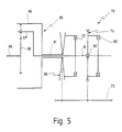
- FIG. 5 shows a variant of an actuating coupling gear 70 that according to the adjusting coupling gear 10 Figures 1 and 2 is modified.
- the input power can initially be from an input shaft 73 to a belt drive 74 with a constant transmission ratio be transmitted.
- the belt drive 74 sits with a loose Bearing 80 on an intermediate shaft 81.
- a first Coupling 85 can be the loose belt pulley of the belt drive 74 are rotatably connected to the intermediate shaft 81.
- Power from input shaft 73 can also be applied to a variator 90 can be transmitted with a variable transmission ratio.
- the Variator 90 is rotatably arranged on a hollow shaft 91.
- a second clutch 92 By means of a second clutch 92, the on the hollow shaft 91 attached pulley of the variator 90 rotatably with the Intermediate shaft 81 are connected.
- a planetary ring gear 95 has a ring gear 96, one Web 97 and a sun gear 98 on.
- An output shaft is 99 non-rotatably connected to the sun gear 98. It stretches in extension of the intermediate shaft 81, on which the concentric Hollow shaft 91 sits.
- the ring gear 96 is rotationally fixed to the hollow shaft 91, and the web 97 is rotationally fixed to the intermediate shaft 81 connected.
- the actuating coupling gear 70 according to FIG. 5 operates as follows:
- the second clutch is in non-power-split operation 92 closed. Then over the hollow shaft 91, which is on the Hollow shaft 91 attached pulley of the variator 90, the second clutch 92 and the intermediate shaft 81, the ring gear 96 non-rotatably connected to the web 97. The planetary ring gear 95 then circulates as a fixed block. The input power will then directly from the input shaft 73 via the variator 90 transferred to the output shaft 99.
- the planetary ring gear 95 acts now as a sum gear.
- Part of the input shaft 73 fed input power of the actuating coupling gear 70 is now via the belt drive 74, the closed first clutch 85 and the intermediate shaft 81 transferred to the web 97.
- On the second part of the input power comes through the variator 90 and the hollow shaft 91 on the ring gear 96.
- the two power components are summed up again and the sum of the sun gear 98 and the output shaft 99 fed.
- the function of the actuating coupling gear corresponds 70 the function of the adjusting coupling gear 10 according to the figures 1 and 2, so that the ratios of the speed diagram 3 are retained.
- FIG. 5 is also with a Reverse gear connected at the output (see Fig. 2), see above a speed diagram similar to that of FIG. 4 is produced.
Description
Die Erfindung betrifft ein Stellkoppelgetriebe mit den Merkmalen gemäß dem Oberbegriff von Anspruch 1. The invention relates to an adjusting coupling transmission with the features according to the preamble of claim 1.
Ein Stellkoppelgetriebe der vorstehend genannten Art ist aus der US 3 340 749 A bekannt.An adjusting coupling gear of the type mentioned above is off the US 3 340 749 A known.
Die Erfindung betrifft ferner ein Stellkoppelgetriebe mit den Merkmalen gemäß dem Oberbegriff von Anspruch 2. The invention further relates to an adjusting coupling gear the features according to the preamble of claim 2.
Ein Stellkoppelgetriebe der vorstehend genannten Art ist aus der US 3 479 908 bekannt.An adjusting coupling gear of the type mentioned above is off U.S. 3,479,908.
Es sind bereits zahlreiche Möglichkeiten bekannt, bei einem Getriebe die gegebene Eingangsdrehzahl in eine gewünschte Ausgangsdrehzahl zu übersetzen. Dabei findet nicht nur eine Übersetzung der Drehzahl sondern auch eine Wandlung des Drehmomentes statt. Man spricht daher insoweit von "Kennungswandlung".Numerous possibilities are already known for a transmission the given input speed into a desired output speed to translate. It doesn't just find a translation the speed but also a conversion of the torque instead of. In this respect, one speaks of "identifier change".
Bei eingängigen Getrieben kann die Drehzahl nur in einem festen Verhältnis übersetzt werden. Bei einem mehrgängigen Getriebe kann ein bestimmtes Drehzahlband abgedeckt werden. Beim Umschalten von einem Gang in einen anderen Gang entsteht jedoch bei den meisten Mehrganggetrieben eine Zugkraftunterbrechung, da der Kraftfluß über das Getriebe kurzzeitig aufgetrennt werden muß, um die drehmomentübertragenden Teile des Getriebes, üblicherweise die Zahnräder, miteinander in Eingriff bringen zu können bzw. voneinander zu lösen.With single-speed gearboxes, the speed can only be set in a fixed one Ratio to be translated. With a multi-speed gearbox a certain speed range can be covered. When switching from one course to another, however, arises in most multi-speed transmissions, an interruption in tractive power, because the power flow through the gearbox is briefly separated the torque-transmitting parts of the gearbox, usually the gears to engage with each other can or solve each other.
Um die bei Gangwechseln in derartigen Getrieben eintretende Zugkraftunterbrechung zu vermeiden, hat man für bestimmte Einsatzfälle, beispielsweise Ackerschlepper, sogenannte Lastschaltgetriebe entwickelt. Diese tragen jedoch zum Teil die Nachteile eines schlechteren Wirkungsgrades sowie eines hohen Bauaufwandes in sich. Bei Gangwechseln müssen auftretende Drehzahldifferenzen zwischen den Gängen durch aufwendige Reibkupplungen überbrückt werden. In den Fällen, in denen man besonderen Wert auf stufenlos wählbare Übersetzungsverhältnisse legt, nimmt man sogar die noch größeren Wirkungsgradverluste von hydrostatischen Antrieben in Kauf, um die Variabilität des Übersetzungsverhältnisses zu erreichen.The one that occurs when changing gears in such transmissions Avoiding an interruption in traction is necessary for certain applications, for example, agricultural tractors, so-called powershift transmissions developed. However, some of them bear the Disadvantages of poorer efficiency and high Construction effort in itself. When changing gears, there must be speed differences between the gears through complex friction clutches be bridged. In cases where you have special Attaches importance to continuously selectable gear ratios, one takes even the greater losses in efficiency of hydrostatic ones Drives in purchase to the variability of the gear ratio to reach.
Eine andere Möglichkeit, variable Übersetzungsverhältnisse zu realisieren, ergibt sich aus dem Einsatz von Variatoren mit verstellbaren Riemenscheiben. Derartige Riemengetriebe können jedoch aufgrund ihrer prinzipbedingten Nachteile nur in eng begrenzten Einsatzfällen genutzt werden.Another way to set variable ratios realize results from the use of variators adjustable pulleys. Such belt transmission can however, due to their inherent disadvantages, only in very limited Use cases.
All diese Getriebekonzepte außer Hydrostaten haben den gemeinsamen Nachteil, daß ein zusätzliches Umkehrgetriebe erforderlich ist, wenn man die Abtriebsdrehzahl umkehren möchte, beispielsweise zur Realisierung eines Rückwärtsganges bei einem Fahrzeug.All of these transmission concepts except hydrostats have one thing in common Disadvantage that an additional reversing gear is required is when you want to reverse the output speed, for example to realize a reverse gear at one Vehicle.
Um die Wirkungsgrade von Lastschaltgetrieben bei zusätzlich vorhandener Stufenlosigkeit zu verbessern, sind aus dem Stand der Technik auch hydrostatisch-mechanisch leistungsverzweigte Lastschaltgetriebe bekannt. Ein Beispiel eines derartigen Lastschaltgetriebes ist in der DE-A-31 47 447 beschrieben. Auch diese Getriebe haben jedoch den Nachteil, daß sie aufgrund der hydrostatischen Baueinheit sehr aufwendig herzustellen sind.In addition to the efficiency of powershift transmissions to improve existing steplessness are from a standing start technology also hydrostatic-mechanical power split Powershift gearbox known. An example of such a powershift transmission is described in DE-A-31 47 447. Also However, these gears have the disadvantage that they are due to the hydrostatic unit are very expensive to manufacture.
Über die vorstehend geschilderten Getriebetypen hinaus sind auch die sogenannten Stellkoppelgetriebe der eingangs genannten Art bekannt. Bislang sind derartige Stellkoppelgetriebe im wesentlichen für stationäre Einsatzfälle konzipiert und gebaut worden.Beyond the gear types described above also the so-called adjusting coupling gearboxes of the aforementioned Kind known. Up to now, such adjusting couplings have been essentially designed and built for stationary applications been.
Unter Stellkoppelgetrieben, wie sie prinzipiell in dem DE-Buch "Dubbel, Taschenbuch für den Maschinenbau", 18. Auflage, Springer-Verlag, 1995, Seiten G 146 bis 148, beschrieben sind, versteht man Getriebe, bei denen die Eingangsleistung aufgeteilt und dann in zwei Anteilen einem Summengetriebe zugeführt wird, dessen Ausgang zugleich den Ausgang des Stellkoppelgetriebes bildet. In einen der beiden verzweigten Leistungspfade ist als Nebengetriebe ein Stellgetriebe mit stufenlos verstellbarer Übersetzung geschaltet.Under adjusting couplings, as they are in principle in the DE book "Dubbel, paperback for mechanical engineering", 18th edition, Springer-Verlag, 1995, pages G 146 to 148, are understood one gearbox where the input power is split and then fed to a summation gear in two parts, the output of which is also the output of the adjusting coupling gear forms. In one of the two branched performance paths is as A secondary gearbox with an infinitely adjustable Translation switched.
Wenn das Summengetriebe ein Planetengetriebe ist, kann die Eingangsleistung im ersten Zweig direkt auf den Steg des Planetengetriebes und im anderen Zweig über das stufenlos verstellbare Stellgetriebe auf das Hohlrad des Planetengetriebes übertragen werden. Den Ausgang des Stellkoppelgetriebes bildet dann das Sonnenrad bzw. die Sonnenradwelle des Planetengetriebes.If the sum gear is a planetary gear, the input power can in the first branch directly onto the planet gear and in the other branch via the continuously adjustable Transfer actuator to the ring gear of the planetary gear become. The output of the actuating coupling gear then forms that Sun gear or the sun gear shaft of the planetary gear.
Durch Verstellung der Übersetzung des Stellgetriebes kann nun die Gesamtübersetzung des Stellkoppelgetriebes ebenfalls stufenlos verstellt werden. Dies ist in weiten Bereichen möglich, und, je nach Auslegung, auch über den Nullpunkt hinweg. Auf diese Weise können also am Ausgang des Stellkoppelgetriebes positive wie auch negative Drehzahlen eingestellt werden.By adjusting the ratio of the actuating gear can now the overall ratio of the adjusting coupling transmission is also continuously variable be adjusted. This is possible in a wide range and, depending on the design, also beyond the zero point. On In this way, positive signals can be output at the adjusting coupling how to set negative speeds.
Bekannte Stellkoppelgetriebe der vorstehend genannten Art haben jedoch den Nachteil, daß die Leistung immer über beide Zweige verzweigt wird, so daß entsprechende Blindleistungen entstehen. Darüber hinaus ist bei vielen Anwendungsfällen von Nachteil, daß das Getriebe unter Last beim Anfahren von der Drehzahl Null des stufenlos verstellbaren Stellgetriebes hochgefahren werden muß. Wenn das Stellgetriebe ein Riemengetriebe mit verstellbaren Riemenscheiben ist, kann dies zu besonderen Problemen deswegen führen, weil das Riemengetriebe beim Anfahren in einer Extremstellung stehen kann, so daß der Riemen sich bei den dann wirkenden hohen Riemenkräften quer zur Laufrichtung durchbiegen kann. Auch der Wirkungsgrad des Getriebes wird in diesem Fahrzustand sehr schlecht.Known adjusting gearboxes of the type mentioned above However, the disadvantage that the performance is always on both branches is branched so that corresponding reactive powers arise. In addition, it is disadvantageous in many applications, that the gearbox under load when starting from zero speed of the infinitely variable actuator can be started up got to. If the actuator is a belt transmission with adjustable Pulleys is there, this can cause special problems cause because the belt transmission when starting in one Extreme position can stand so that the belt is then at the Deflect high belt forces acting transversely to the direction of travel can. The efficiency of the transmission is also in this driving state very bad.
Derartige Anwendungsfälle gibt es jedoch häufig im Fahrzeugbau, also einem Bereich, in dem Stellkoppelgetriebe bislang allenfalls vereinzelt eingesetzt worden sind. Die genannten Probleme entstehen vor allem bei landwirtschaftlich genutzten Fahrzeugen, bei denen Getriebe für den Antrieb landwirtschaftlicher Geräte verwendet werden. Ein typisches Anwendungsbeispiel hierfür ist ein Mähdrescher, dessen Dreschtrommel über ein Getriebe angetrieben werden soll. Wenn die Dreschtrommel aus dem Stillstand angefahren werden soll, können sich bei Verwendung herkömmlicher Stellkoppelgetriebe die vorstehend genannten Nachteile einstellen. Aus diesem Grund sind derartige Einsatzfälle für Stellkoppelgetriebe bislang nicht bekannt geworden. Such applications are common in vehicle construction, in other words, an area in which adjusting couplings have so far been at best have been used occasionally. The problems mentioned arise mainly in agricultural vehicles, where gearboxes for driving agricultural Devices are used. A typical application example for this is a combine harvester whose threshing drum has a gearbox to be driven. When the threshing drum stops can be approached using conventional Coupling gearbox the disadvantages mentioned above to adjust. For this reason, such applications are not yet known for actuating coupling gearboxes.
Aus dem eingangs genannten Dokument US 3 340 749 ist ein Stellkoppelgetriebe bekannt, bei dem das Planeten-Summengetriebe als Umlaufrädergetriebe ausgebildet ist. Umlaufrädergetriebe zeichnen sich dadurch aus, daß sie zwei Zahnradpaare mit je zwei miteinander kämmenden Zahnrädern umfassen, von denen jeweils ein Zahnrad drehfest auf einer gemeinsamen Stegwelle angeordnet ist, während das jeweils andere Zahnrad drehfest mit einer Eingangswelle bzw. einer Ausgangswelle des Umlaufrädergetriebes verbunden ist. Das bekannte Getriebe sieht auch vor, daß die jeweils anderen Zahnräder unterschiedliche Zähnezahlen aufweisen, nämlich das eingangsseitige Zahnrad eine kleinere Zähnezahl als das ausgangsseitige Zahnrad. Schließlich ist die Stegwelle drehbar in einem Steggehäuse gelagert, das drehfest mit einer Hohlwelle verbunden ist.From the document US 3 340 749 mentioned at the outset is an actuating coupling gear known in which the planetary sum gear as Epicyclic gear is formed. Draw planetary gear are characterized in that they have two pairs of gears, each with two intermeshing gears, each of which a gear rotatably arranged on a common web shaft is, while the other gear is rotatably with an input shaft or an output shaft of the epicyclic gear connected is. The known transmission also provides that the each other gears have different numbers of teeth, namely the input side gear has a smaller number of teeth than the output gear. Finally, the bridge shaft rotatably mounted in a bar housing that rotates with a hollow shaft is connected.
In dem eingangs erwähnten Dokument US 3 479 908 ist ein Stellkoppelgetriebe beschrieben, bei dem das Planeten-Summengetriebe hingegen als Hohlradgetriebe ausgebildet ist. Das Hohlradgetriebe umfaßt einen Planetensatz, dessen Steg den ersten Eingang bildet.In the above-mentioned document US 3,479,908 there is an adjusting coupling gear described, in which the planetary sum gear however, is designed as a ring gear. The ring gear includes a planetary set, the bridge of which is the first entrance forms.
Insofern gleiche Stellkoppelgetriebe mit einer Umlaufrädergetriebestufe sind auch in den Dokumenten US 4 990 127 sowie WO 95/17621 beschrieben.In this respect, the same coupling mechanism with one epicyclic gear stage are also in documents US 4 990 127 as well WO 95/17621.
Der Erfindung liegt demgegenüber die Aufgabe zugrunde, Stellkoppelgetriebe der eingangs genannten Art dahingehend weiterzubilden, daß unter Beibehaltung der damit erzielbaren Vorteile (großer Übersetzungsbereich, Möglichkeit der Drehrichtungsumkehr, verlustarmer Betrieb in den in der Praxis häufigsten Betriebsarten, stufenlose Variation der Abtriebsdrehzahl unter Last, hoher Wirkungsgrad und kostengünstige Fertigung) eine Bauweise erzielt wird, bei der unzulässig hohe Drehzahlen vermieden werden.In contrast, the invention is based on the object of actuating coupling gears of the type mentioned at the outset, that while maintaining the benefits achievable with it (large translation range, possibility of reversing the direction of rotation, low-loss operation in the most common operating modes in practice, stepless variation of the output speed below Load, high efficiency and cost-effective production) Construction is achieved in which impermissibly high speeds avoided become.
Bei dem eingangs als erstes genannten Stellkoppelgetriebe wird diese Aufgabe erfindungsgemäß durch die Merkmale des Anspruchs 1 gelöst.In the case of the actuating coupling gearbox mentioned at the beginning as the first this object is achieved according to the invention by the features of claim 1.
Bei einem Stellkoppelgetriebe der eingangs als zweites genannten Art wird die Aufgabe erfindungsgemäß durch die Merkmale des Anspruchs 2 gelöst.In the case of an actuating coupling gear which is mentioned as the second one at the beginning The task is solved according to the invention by the features of claim 2.
Die der Erfindung zugrundeliegende Aufgabe wird auf diese Weise vollkommen gelöst, wenn gemäß der vorstehenden Festlegung bei einem Stellkoppelgetriebe mit einer Planeten-Umlaufgetriebestufe der Variator an dem Steg und der konstante Leistungspfad am großen Sonnenrad angreift, während bei einem Stellkoppelgetriebe mit Planeten-Hohlradgetriebestufe der Variator an dem Hohlrad und der konstante Leistungspfad an dem Steg angreift. Bei einem derart ausgebildeten Getriebe werden unzulässig hohe Drehzahlen vermieden. In beiden Fällen ist es möglich, in an sich bekannter Weise alternativ in einem lei stungsverzweigten und einem nicht leistungsverzweigten Bereich zu fahren, wobei das Anfahren aufgrund des höheren Drehmoments bei laufenden Wellen erfolgen kann.The object on which the invention is based is achieved in this way completely solved if according to the above definition at an adjusting coupling gear with a planetary epicyclic gear stage the variator on the bridge and the constant Power path attacks on the large sun gear while at one Coupling gear with planetary ring gear stage of the variator on the ring gear and the constant power path on that Bridge attacks. With a gear designed in this way Avoid impermissibly high speeds. In both cases it is possible, alternatively in a manner known per se in a lei branched and a non-branched area to drive, the starting due to the higher torque can take place with running waves.
Durch wahlweise Ansteuerung der Kupplungen kann erreicht werden, daß die Antriebsleistung einmal nur über den Variator auf den Ausgang durchgeschaltet wird, während andererseits auch ein leistungsverzweigter Betrieb in herkömmlicher Weise möglich ist. Der Ausgang des Planeten-Summengetriebes treibt die Ausgangswelle daher in einer leistungsverzweigten Betriebsart bei geschlossener erster Kupplung und geöffneter zweiter Kupplung an, in einer nicht-leistungsverzweigten Betriebsart hingegen bei geöffneter erster Kupplung und geschlossener zweiter Kupplung.By optionally controlling the clutches, that the drive power only once on the variator the output is switched through, while on the other hand also power split operation possible in a conventional manner is. The output of the planetary sum gear drives the output shaft therefore in a power split mode closed first clutch and opened second clutch on, however, in a non-power-split operating mode with the first clutch open and the second clutch closed.
Auf diese Weise kann ein großer Bereich der möglichen Einsatzfälle des Getriebes dadurch abgedeckt werden, daß lediglich mit dem Variator gearbeitet wird, so daß die im Planeten-Summengetriebe ansonsten anfallenden Blindleistungen nicht mehr auftreten.This allows a wide range of possible uses of the transmission are covered in that only with the variator is worked so that in the planetary sum gear otherwise no reactive power occur.
Es wird somit ein Planeten-Summengetriebe eingesetzt, bei dem die Eingangsleistung in zwei Leistungspfade aufgeteilt wird. Während der erste Leistungspfad z.B. über einen drehfest auf der Eingangswelle befestigten Variator geleitet wird, der die Kraft über einen Breitkeilriemen auf das Getriebe überträgt, wird der zweite Leistungsanteil über einen Konstant-Antrieb mit fester Übersetzung in das Getriebe geleitet. Bevorzugt ist, wenn der Variator ein Riemengetriebe mit verstellbaren Riemenscheiben ist, der weiter bevorzugt unmittelbar von der Eingangswelle angetrieben wird. Wenn der Konstant-Antrieb ein Riementrieb mit festen Riemenscheiben ist, kann sowohl eine verstellbare wie auch eine feste Riemenscheibe jeweils drehfest auf der Eingangswelle angeordnet werden.A planetary sum gear is thus used in the the input power is divided into two power paths. While the first power path e.g. over a non-rotatable attached to the input shaft attached variator, which the Force on a wide V-belt transmits the transmission, the second power share is over a constant drive with a fixed ratio in the transmission headed. It is preferred if the variator is a belt transmission with adjustable pulleys, which is more preferred is driven directly by the input shaft. If the Constant drive is a belt drive with fixed pulleys, can have both an adjustable and a fixed pulley each be arranged in a rotationally fixed manner on the input shaft.
Bei bevorzugten Ausgestaltungen der Erfindung sind die Kupplungen betätigbar, vorzugsweise indem die Kupplungen im Übergangspunkt zwischen zwei Bereichen der Abtriebsdrehzahl oder beim Starten alternativ betätigbar sind.In preferred configurations of the invention, the couplings are operable, preferably by the couplings in the transition point between two ranges of the output speed or when starting can be operated alternatively.
In bevorzugter Weiterbildung dieser Ausführungsbeispiele ist im ersten, leistungsverzweigten Bereich nur die erste Kupplung geschlossen, derart, daß die auf die Eingangswelle eingespeiste Leistung verzweigt und zu einem Teil im Variator und zum anderen Teil im Planeten-Summengetriebe kennungsgewandelt wird, während im zweiten, nicht-leistungsverzweigten Bereich nur die zweite Kupplung geschlossen ist, derart, daß die auf die Eingangswelle eingespeiste Leistung ausschließlich im Variator kennungsgewandelt wird.In a preferred development of these exemplary embodiments in the first, power-split area only the first clutch closed, such that the fed on the input shaft Performance branches and partly in the variator and partly Part of the planetary sum gear is converted while in the second, non-power-split area only the second Clutch is closed, such that the on the input shaft Power fed in changed in the variator only becomes.
Bei einer Variante dieses Ausführungsbeispiels wird im zweiten Bereich das Planeten-Summengetriebe überbrückt, während bei einer zweiten Variante das Planeten-Summengetriebe im zweiten Bereich als geschlossener Block umläuft.In a variant of this embodiment, the second Area bridges the planetary sum gear while at a second variant, the planetary sum gear in the second Area revolves as a closed block.
Mittels der beiden unabhängig voneinander betätigbaren Kupplungen können die Abtriebsdrehzahlen in zwei Bereiche aufgeteilt werden, nämlich in einen leistungsverzweigten und einen nicht-leistungsverzweigten Bereich. By means of the two independently operable clutches the output speeds can be divided into two areas, namely in a power-split and a non-power split Area.
Zur Erreichung eines möglichst hohen Wirkungsgrades ohne Blindleistung sollte der Hauptarbeitsbereich des vom Getriebe angetriebenen Aggregates im nicht-leistungsverzweigten Bereich liegen, der dem Regelbereich des Variators entspricht. Die beiden Bereiche schließen aneinander an.To achieve the highest possible efficiency without Reactive power should be the main working area of the gearbox driven units in the non-power-split area lie, which corresponds to the control range of the variator. The two Areas are contiguous.
Bei einer entsprechend günstig gewählten Zahl der Zähne auf den Zahnrädern im Summengetriebe ist es - ausgehend von einer Schaltdrehzahl, bei der die Drehzahl der Antriebswelle identisch ist mit der Drehzahl der Abtriebswelle - möglich, bei einer ansteigenden vom Variator übertragenen Drehzahl die Abtriebsdrehzahl auf Null und bei weiter steigender Variatordrehzahl schließlich die Abtriebsdrehzahl unter Drehrichtungsumkehr in den negativen Bereich zu regeln.With an appropriately chosen number of teeth it is the gears in the summation gear - starting from one Switching speed at which the speed of the drive shaft is identical is possible with the speed of the output shaft - at one increasing speed transmitted by the variator the output speed to zero and as the variator speed increases finally the output speed while reversing the direction of rotation in to regulate the negative range.
Die zwei Bereiche werden durch die zwei Kupplungen verknüpft, wobei beide Kupplungen bei Drehzahlgleichheit des ersten und des zweiten Bereichs unter Last schaltbar sind. Die zweite Kupplung kuppelt den variablen Leistungspfad über den Variator, die erste Kupplung kuppelt den konstanten Leistungspfad. Durch wahlweise Ansteuerung der Kupplungen kann nun erreicht werden, daß die Antriebsleistung bei Schaltung der zweiten, den Variator kuppelnden Kupplung nur über den Variator in herkömmlicher Weise auf den Ausgang durchgeschaltet wird, während bei Schaltung der ersten Kupplung ein leistungsverzweigter Betrieb möglich ist.The two areas are linked by the two couplings, where both clutches at the same speed of the first and of the second area are switchable under load. The second Coupling couples the variable power path via the variator, the first clutch couples the constant power path. By optional control of the clutches can now be achieved, that the drive power when switching the second, the variator coupling clutch only via the variator in a conventional manner is switched through to the output, while when switching the branched operation is possible after the first clutch.
Im Schaltpunkt, in dem Drehzahlgleichheit des ersten und des zweiten Bereichs vorliegt, können kurzzeitig auch beide Kupplungen geschaltet sein. Durch Lösen der einen oder der anderen Kupplung kann zwischen den beiden Bereichen unter Last und ohne Zugkraftunterbrechung hin- und hergeschaltet werden. Ein weiterer wesentlicher Vorteil besteht dabei darin, daß die Kupplungen als formschlüssige Kupplungen ausgebildet werden können, also in verhältnismäßig einfacher und preiswerter Bauart. In the switching point, in which the speed equality of the first and the second area, both clutches can also be used for a short time be switched. By loosening one or the other Clutch can be under load and without between the two areas Traction interruption can be switched back and forth. Another The main advantage is that the couplings can be designed as positive couplings, so in a relatively simple and inexpensive design.
Eine gute Wirkung wird erzielt, wenn die Übersetzungen im Variator und dem Planeten-Summengetriebe so gewählt sind, daß etwa in der Mitte des Variatorbereichs im leistungsverzweigten Bereich die Abtriebsdrehzahl der Ausgangswelle gleich Null ist.A good effect is achieved if the translations in Variator and the planetary sum gear are chosen so that approximately in the middle of the variator range in the power split Range the output speed of the output shaft is zero.
Beim Startvorgang sind somit beide Kupplungen offen, und der Variator wird automatisch so geregelt, daß die Getriebeabtriebsdrehzahl Null beträgt. Dann wird die erste Kupplung für den Konstant-Antrieb geschlossen und die Abtriebsdrehzahl auf einen von Null verschiedenen Wert geregelt.When starting, both clutches are open, and the Variator is automatically controlled so that the gearbox output speed Is zero. Then the first clutch for the Constant drive closed and the output speed to one Value regulated from zero.
Diese Maßnahme hat den Vorteil, daß zum Anfahren eines vom Getriebe angetriebenen Aggregats nicht von der Drehzahl Null im Variator, sondern vielmehr von einer endlichen Drehzahl ausgegangen werden kann, so daß der Variator mit laufenden Riemen im Bereich seiner höchsten Leistungsdichte belastet wird.This measure has the advantage that to start one of Gearbox driven unit not from zero speed in the variator, but rather a finite speed can be assumed, so that the variator with running belts in the area of its highest power density.
Ferner wird bevorzugt zum Anfahren eines vom Stellkoppelgetriebe angetriebenen Aggregates die Abtriebsdrehzahl über den Variator zunächst auf Null eingestellt und dann bei geschlossener erster Kupplung die Abtriebsdrehzahl auf einen von Null verschiedenen Wert geregelt. Sofern die Abtriebsdrehzahl nicht bereits ohnehin auf Null eingestellt ist und mindestens eine der beiden Kupplungen noch geschlossen ist, werden in bevorzugter Weiterbildung dieser Variante bei einer zunächst von Null verschiedenen Abtriebsdrehzahl zuerst beide Kupplungen geöffnet und die Abtriebsdrehzahl dann über den Variator auf Null eingestellt.It is also preferred to start one of the actuating coupling gears driven unit the output speed via the variator initially set to zero and then with the first one closed Clutch the output speed to a non-zero Value regulated. Unless the output speed is already there is set to zero and at least one of the two clutches is still closed, be in preferred training this variant with an initially different from zero Output speed first both clutches opened and the The output speed is then set to zero using the variator.
Bevorzugt ist bei der Erfindung ferner, wenn das Getriebe mit konstanter Antriebsdrehzahl der Eingangswelle angetrieben wird. It is also preferred in the invention if the transmission with constant drive speed of the input shaft is driven.
Weiterhin ist bevorzugt, wenn die Abtriebsdrehzahl der Ausgangswelle stufenlos von positiven über Null zu negativen Drehzahlen einstellbar ist.It is further preferred if the output speed of the output shaft stepless from positive to zero to negative speeds is adjustable.
Ferner ist besonders bevorzugt, wenn erfindungsgemäß beim Umschalten zwischen den Bereichen die Drehzahlen an den Kupplungen jeweils eingangs- und ausgangsseitig gleich sind, derart, daß ohne Zugkraftunterbrechung geschaltet wird.It is also particularly preferred if according to the invention Switching between the ranges the speeds on the clutches are respectively the same on the input and output sides, such that that is switched without interruption of traction.
Ein erfindungsgemäß ausgestaltetes Getriebe kann sowohl als stufenloses Vorschaltgetriebe für Fahrantriebe in Fahrzeugen als auch als stufenloses Getriebe zum Antrieb von Maschinenkomponenten, beispielsweise einer Dreschtrommel in einem Mähdrescher, eingesetzt werden. In Fahrzeugen, die mit einem erfindungsgemäßen Getriebe ausgestattet werden, ist es möglich, bei konstanter (optimaler) Motordrehzahl die Getriebeübersetzung stufenlos zu regeln und unter Last zu rangieren (vorwärts und rückwärts zu fahren), ohne kuppeln oder Gänge vorwählen zu müssen. Bei Realisierung des Hauptarbeitsbereiches im nicht-leistungsverzweigten Bereich können die sonst in einem Summengetriebe anfallenden Blindleistungen vermieden werden. Auf diese Weise wird ein ökonomischer Betrieb des Fahrzeugs oder der Maschine möglich. Wenn man den üblichen Variatorantrieb von Dreschtrommeln durch ein erfindungsgemäßes Getriebe ersetzt, ist es nicht nur möglich, auf das bisher zwangsläufig erforderliche Reduziergetriebe mit den nachteiligen Schaltvorgängen zu verzichten; man kann zusätzlich eine Reversierfunktion realisieren, die die bekannten Antriebskonzepte nicht ermöglichen würden.A transmission designed according to the invention can be used both as continuously variable primary transmission for travel drives in vehicles as well as a continuously variable transmission for driving machine components, for example a threshing drum in one Combine harvesters. In vehicles with a Gears according to the invention are equipped, it is possible at constant (optimal) engine speed, the gear ratio steplessly regulated and maneuvered under load (forward and to reverse) without clutching or preselecting gears have to. When realizing the main work area in the non-performance-split The range can otherwise be in a summation gear reactive powers are avoided. To this An economical operation of the vehicle or the Machine possible. If you take the usual variator drive from Threshing drums replaced by a transmission according to the invention, it is not only possible to focus on what was previously inevitable Reduction gear with the disadvantageous switching operations to renounce; you can also use a reversing function realize that the known drive concepts do not allow would.
Zu beachten ist, daß bei Realisierung der Erfindung mittels eines Planeten-Umlaufgetriebes der Variator an dem Steg und der konstante Leistungspfad am großen Sonnenrad und bei einem Planeten-Hohlradgetriebe der Variator an dem Hohlrad und der konstante Leistungspfad an dem Steg angreifen muß, wenn unzulässige Drehzahlen innerhalb des Summengetriebes vermieden bzw. die Funktion überhaupt dargestellt werden soll.It should be noted that when implementing the invention by means of a planetary planetary gear the variator on the web and the constant power path at the big sun gear and at one Planetary ring gear the variator on the ring gear and the constant power path must attack the web if inadmissible Avoid speeds within the total gearbox or the function should be displayed at all.
Bei Ausgestaltung des erfindungsgemäßen Getriebes als Planeten-Umlaufgetriebe sind zwei Zahnradpaare mit je zwei miteinander kämmenden Zahnrädern vorgesehen. Von diesen ist jeweils ein Zahnrad drehfest auf einer Stegwelle angeordnet, während das jeweils andere Zahnrad drehfest mit einer den ersten Eingangspfad bildenden Eingangswelle bzw. einer den Ausgang bildenden Ausgangswelle verbunden ist. Ferner ist die Stegwelle drehbar in einem Steggehäuse gelagert. Das Steggehäuse ist drehfest mit einer den zweiten Eingangspfad bildenden Hohlwelle verbunden. Möglich wäre beispielsweise auch ein Planetendoppelrad, das drehbar auf der drehfesten Stegwelle gelagert ist. Bei Ausgestaltung des erfindungsgemäßen Getriebes als Planeten-Hohlradgetriebe ist der Variator mit dem Hohlrad verbunden. Die Kupplungen für den Variator und den Konstant-Antrieb wirken bei Betätigung auf die durch das Hohlrad geführte Stegwelle, die mit dem Planetenrad verbunden ist, während die Ausgangswelle am Sonnenrad des Planetensatzes befestigt ist.When designing the transmission according to the invention as a planetary planetary gear are two pairs of gears, each with two meshing gears provided. There is one of each Gear rotatably arranged on a web shaft, while the each other gear rotatably with the first input path forming input shaft or one forming the output Output shaft is connected. Furthermore, the web shaft is rotatable stored in a web housing. The bridge housing is non-rotatable connected to a hollow shaft forming the second input path. For example, a planetary double wheel would also be possible is rotatably mounted on the non-rotatable web shaft. When designing of the transmission according to the invention as a planetary ring gear the variator is connected to the ring gear. The couplings for the variator and the constant drive act when actuated on the web shaft guided through the ring gear, which is connected to the Planet gear is connected while the output shaft is on the sun gear the planetary gear set is attached.
Bei den hier beschriebenen Planetengetriebe-Bauarten ist ein kleiner Variator-Regelbereich möglich. Unter einem kleinen Variator-Regelbereich ist in einer praktischen Ausführungsform beispielsweise ein Variatorbereich von ivar = 2,3 zu verstehen. Von diesem Wert kann jedoch auch nach oben oder unten abgewichen werden. Bei dem vorgeschlagenen Variatorbereich von ivar = 2,3 ergibt sich der Vorteil, daß mindestens 50 % der maximalen Vorwärtsdrehzahl auch für den Rückwärtsbetrieb zur Verfügung stehen. Die Realisierung der erforderlichen Getriebeübersetzung ist bei einem Planeten-Umlaufgetriebe einfacher, weil man im Vergleich zum Planeten-Hohlradgetriebe größere Freiheiten bei der Wahl der Übersetzung hat. Damit ist das grundsätzliche Ziel, möglichst einen kleinen Variator-Regelbereich anzustreben, da dieser eine höhere Leistungsdichte hat, im Planeten-Umlaufgetriebe leichter realisierbar. Unter hoher Leistungsdichte wird hier ein Variator verstanden, der wegen des kleineren Regelbereiches größere Kleinstdurchmesser und bei festgelegten Außendurchmessern eine schmale obere Riemenbreite bei großer Riemenhöhe sowie übliche Abtriebsdrehzahlen hat, so daß es bei hoher Beanspruchung des Riemens nicht zu einer Durchbiegung des Riemens quer zur Laufrichtung kommen kann. Im Planeten-Umlaufgetriebe ergibt sich zusätzlich der Vorteil, daß die Drehzahlen der Planetenräder niedriger liegen können als bei den meisten Planetengetrieben mit Hohlrad.A small variator control range is possible with the planetary gear types described here. In a practical embodiment, a small variator control range means, for example, a variator range of i var = 2.3. However, this value can also be deviated up or down. With the proposed variator range of i var = 2.3, there is the advantage that at least 50% of the maximum forward speed is also available for reverse operation. The implementation of the required gear ratio is easier with a planetary epicyclic gear because, compared to the planetary ring gear, you have greater freedom in choosing the gear ratio. The fundamental goal of striving for a small variator control range, since this has a higher power density, is easier to achieve in the planetary epicyclic gearbox. A high power density is understood here to mean a variator which, due to the smaller control range, has larger small diameters and, with fixed outer diameters, a narrow upper belt width with a large belt height and usual output speeds so that the belt does not deflect transversely to the direction of travel when the belt is subjected to high loads can. In planetary planetary gears there is the additional advantage that the speeds of the planet gears can be lower than in most planetary gears with a ring gear.
Durch die beschriebene Anordnung entsteht ein extrem kompaktes, leistungsdichtes und im Aufbau einfaches Getriebe, das den aufgabengemäßen Anforderungen genügt.The arrangement described creates an extremely compact, high-performance gearbox with a simple construction that task requirements are sufficient.
In weiterer Ausgestaltung der Erfindung ist es möglich, durch Anbau eines Wendegetriebes an ein erfindungsgemäßes Planeten-Umlauf- oder -Hohlradgetriebe auch bei Drehzahlumkehr rückwärts im nicht-leistungsverzweigten Bereich ohne Blindleistungen Antriebsleistungen zu übertragen. Die Umkehr der Drehrichtung wird in dieser Ausgestaltung der Erfindung durch das Wendegetriebe bewirkt. Erreicht die Abtriebsdrehzahl des Planeten-Summengetriebes den Wert Null, kann die Wendekupplung geöffnet und das Wendegetriebe geschaltet werden. Die Variatordrehzahl wird bei Erreichen der Abtriebsdrehzahl Null des Planeten-Summengetriebes nicht weiter erhöht. Nach Betätigung des Wendegetriebes wird sie vielmehr verringert, da ansonsten eine unerwünschte Drehzahlumkehr an der Abtriebswelle des Planeten-Summengetriebes eintreten würde. Wird die Variatordrehzahl bei umgekehrter Drehrichtung zur Erhöhung der negativen Abtriebsdrehzahl so weit reduziert, daß sie mit der Drehzahl des Konstant-Antriebs übereinstimmt, kann in oben beschriebener Weise durch Betätigung der Kupplungen im Planeten-Summengetriebe vom leistungsverzweigten auf den nicht-leistungsverzweigten Bereich umgeschaltet werden, in dem dann keine Blindleistungen mehr auftreten.In a further embodiment of the invention, it is possible to Attachment of a reversing gearbox to an epicyclic planetary or ring gear even when reversing speed in the non-power-split area without reactive power To transfer drive power. Reversing the direction of rotation is in this embodiment of the invention by the reverse gear causes. Reaches the output speed of the planetary gear the value zero, the reversible coupling can be opened and the reversing gear can be switched. The variator speed becomes zero when the output speed of the planetary sum gear is reached not further increased. After pressing the Reverse gear, it is rather reduced, otherwise one unwanted speed reversal on the output shaft of the planetary gear would occur. The variator speed at Reverse direction of rotation to increase the negative output speed reduced so far that it changes with the speed of the Constant drive matches, can be described in the above Way by actuating the clutches in the planetary sum gear from the power split to the non power split Range can be switched in which then no reactive power occur more.
Je nach Schaltstellung des Wendegetriebes kann man bei der hier vorgeschlagenen Anordnung das volle Drehzahlband der Abtriebswelle sowohl vorwärts als auch rückwärts nutzen. Die niedrigeren Drehzahlen der Abtriebswelle unterhalb der minimalen Variatordrehzahl bis zu einer Abtriebsdrehzahl Null sind bei geschlossener Kupplung des Konstant-Antriebes leistungsverzweigt und die höheren Drehzahlen bei geschlossener Kupplung des Variators nicht-leistungsverzweigt stufenlos regelbar.Depending on the shift position of the reversing gearbox, you can use the here proposed arrangement the full speed range of the output shaft use both forward and backward. The lower ones Output shaft speeds below the minimum variator speed up to an output speed of zero when closed Coupling of the constant drive power split and the higher speeds when the variator clutch is closed Infinitely variable, not power-split.
In weiterer Ausgestaltung der Erfindung ist es möglich, bei besonders beengten Einbauverhältnissen eingangsseitig den Konstant-Antrieb und/oder den Variator an anderer Stelle der Maschine oder des Fahrzeugs als das Planeten-Summengetriebe anzuordnen. Die vom Konstant-Antrieb und/oder vom Variator zu übertragenden Leistungen können dann mittels an sich bekannter Kraftübertragungselemente in einer oder mehreren Stufen zum jeweiligen Getriebeeingang geführt werden.In a further embodiment of the invention, it is possible to particularly cramped installation conditions on the input side Constant drive and / or the variator elsewhere Machine or vehicle as the planetary sum gear to arrange. Those from the constant drive and / or from the variator too Transferring services can then be done by means of known Power transmission elements in one or more stages the respective gearbox input.
Weitere Vorteile ergeben sich aus der Beschreibung und der beigefügten Zeichnung.Further advantages result from the description and the attached drawing.
Es versteht sich, daß die vorstehend genannten und die nachstehend noch zu erläuternden Merkmale nicht nur in der jeweils angegebenen Kombination, sondern auch in anderen Kombinationen oder in Alleinstellung verwendbar sind, ohne den Rahmen der vorliegenden Erfindung zu verlassen. It is understood that the above and those below Features to be explained not only in each case specified combination, but also in other combinations or can be used alone, without the scope of to leave the present invention.
Ausführungsbeispiele der Erfindung sind in der Zeichnung dargestellt und werden in der nachfolgenden Beschreibung näher erläutert. Es zeigen:
- Fig. 1
- eine schematisierte Darstellung eines Ausführungsbeispiels eines erfindungsgemäßen Stellkoppelgetriebes in Form eines Planeten-Umlaufgetriebes;
- Fig. 2
- das Getriebe gemäß Fig. 1, in noch weiter schematisierter Darstellung;
- Fig. 3
- ein Drehzahldiagramm zur Erläuterung des Getriebes gemäß Fig. 2 ohne Berücksichtigung eines nachgeschalteten Wendegetriebes;
- Fig. 4
- ein Drehzahldiagramm, ähnlich dem der Fig. 3, jedoch zur Erläuterung des Getriebs gemäß Fig. 2 mit nachgeschaltetem Wendegetriebe; und
- Fig. 5
- eine weitere Darstellung, ähnlich Fig. 2, jedoch für ein weiteres Ausführungsbeispiel der Erfindung in Form eines Planeten-Hohlradgetriebes.
- Fig. 1
- a schematic representation of an embodiment of an adjusting coupling transmission according to the invention in the form of a planetary planetary gear;
- Fig. 2
- 1, in an even more schematic representation;
- Fig. 3
- a speed diagram for explaining the transmission of Figure 2 without considering a downstream reversing gear.
- Fig. 4
- a speed diagram, similar to that of Figure 3, but for explaining the transmission of Figure 2 with downstream reversing gear. and
- Fig. 5
- another representation, similar to FIG. 2, but for a further embodiment of the invention in the form of a planetary ring gear.
In Fig. 1 bezeichnet 10 insgesamt ein Stellkoppelgetriebe. Ein
mit einem Pfeil symbolisierter Getriebeeingang 12 wird durch
eine Eingangswelle 13 gebildet. Ein Riementrieb 14 mit konstantem
Übersetzungsverhältnis weist eine erste Riemenscheibe 15, eine
zweite Riemenscheibe 16 sowie einen diese umschlingenden Riemen
17 auf. Die erste Riemenscheibe 15 ist drehfest mit der Eingangswelle
13 verbunden. In Fig. 1, 10 designates a total of an actuating coupling gear. On
Wie mit 20 angedeutet, sitzt die zweite Riemenscheibe 16 mit
einer losen Lagerung auf einer Zwischenwelle 21. Die Zwischenwelle
21 erstreckt sich parallel zur Eingangswelle 13. Mittels
einer ersten Kupplung 25 kann die zweite Riemenscheibe 16 in
drehfeste Verbindung mit der Zwischenwelle 21 gebracht werden.As indicated at 20, the
Ein Variator 30 mit stufenlos einstellbarem Übersetzungsverhältnis
ist beim Stellkoppelgetriebe 10 gemäß Fig. 1 als
Riemengetriebe ausgebildet. Der Variator 30 weist eine erste
Riemenscheibe 31, eine zweite Riemenscheibe 32 sowie einen diese
umschlingenden Riemen 33 auf. Die erste Riemenscheibe 31 ist
ebenfalls drehfest auf der Eingangswelle 13 angeordnet.A variator 30 with a continuously adjustable transmission ratio
is in the adjusting
Demgegenüber sitzt die zweite Riemenscheibe 32 des Variators
30 auf einer Hohlwelle 40, die eine Ausgangswelle 41 umgibt.
Die Hohlwelle 40 und die Ausgangswelle 41 verlaufen ebenfalls
parallel zur Eingangswelle 13. Sie sind darüber hinaus koaxial
zur Zwischenwelle 21 angeordnet.In contrast, the
Mittels einer zweiten Kupplung 45 kann die zweite Riemenscheibe
32 des Variators 30 mit der Hohlwelle 40 drehfest mit der
Ausgangswelle 41 verbunden werden.By means of a second clutch 45, the second pulley can
32 of the variator 30 with the
Die Betätigungs- und Steuereinrichtungen für die Kupplungen
25, 45 sowie den Variator 30 sind in Fig. 1 der Übersichtlichkeit
halber nicht dargestellt. Diese Elemente sind an sich bekannt
und brauchen daher im vorliegenden Zusammenhang nicht nochmals
im einzelnen beschrieben zu werden.The actuation and control devices for the
Zwischen die Zwischenwelle 21 einerseits und die Ausgangswelle
41 mit Hohlwelle 40 andererseits ist ein insgesamt mit 47
bezeichnetes Umlaufrädergetriebe geschaltet. Das Umlaufrädergetriebe
47 weist ein Steggehäuse 48 auf. Das Steggehäuse 48
ist an seiner in Fig. 1 linken Seite drehfest mit der Hohlwelle
40 verbunden. Auf seiner in Fig. 1 rechten Seite ist das
Steggehäuse 48 auf der Zwischenwelle 21 gelagert.Between the
Im radialen Abstand von der Zwischenwelle 21 und der Ausgangswelle
41 ist eine Stegwelle 49 im Steggehäuse 48 drehbar gelagert
bzw. ein Planetendoppelrad 52/53 drehbar auf der drehfesten
Stegwelle 49 gelagert.At a radial distance from the
Innerhalb des Steggehäuses 48 trägt die Zwischenwelle 21 drehfest
ein erstes Zahnrad 51, das mit einem auf der Stegwelle 49
drehfest befestigten zweiten Zahnrad 52 kämmt. Ein drittes,
ebenfalls mit der Stegwelle 49 drehfest verbundenes Zahnrad
53 kämmt mit einem vierten Zahnrad 54, das drehfest auf der
Ausgangswelle 41 angeordnet ist. Auf diese Weise werden zwei
Radsätze gebildet, nämlich vom ersten und vom zweiten Zahnrad
51/52 sowie vom dritten und vom vierten Zahnrad 53/54. Die
zugehörigen Zähnezahlen der vier Zahnräder 51 bis 54 sind in
Fig. 1 mit Z1 bis Z4 bezeichnet.Within the
Das Stellkoppelgetriebe 10 gemäß Fig. 1 ist in Fig. 2 nochmals
weiter schematisiert dargestellt. Darin ist ferner die Drehzahl
der zweiten Riemenscheibe 16 des Riementriebes 14 als Antriebsdrehzahl
mit nan bezeichnet, die Drehzahl der Hohlwelle 40 als
Variatordrehzahl nvar und die Drehzahl der Ausgangswelle 41
schließlich als Abtriebsdrehzahl nab.The adjusting
In Fig. 2 ist schließlich noch angedeutet, daß an den Ausgang
des Getriebes 10 ein Wendegetriebe 55 angeschlossen werden kann.
Diese Option ist durch eine gestrichelte Linie in Fortsetzung
der Ausgangswelle sowie eine senkrechte, strichpunktierte Linie
angedeutet. In Fig. 2 it is finally indicated that at the exit
the
Aufbau, Funktion und Auswirkungen des Wendegetriebes 55 werden
weiter unten anhand der Fig. 4 noch erläutert werden.Structure, function and effects of the
Fig. 3 zeigt ein Diagramm, in dem die Variatordrehzahl nvar auf der Ordinate und die Abtriebsdrehzahl nab auf der Abszisse aufgetragen ist. Die beiden Achsen sind dabei mit Drehzahlwerten parametriert, die einem realisierten Ausführungsbeispiel der Erfindung entnommen wurden. Diese Zahlen sind daher lediglich beispielhaft zu verstehen und schränken den Rahmen der vorliegenden Erfindung nicht ein.FIG. 3 shows a diagram in which the variator speed n var is plotted on the ordinate and the output speed n ab on the abscissa. The two axes are parameterized with speed values that were taken from a realized embodiment of the invention. These numbers are therefore to be understood only as examples and do not limit the scope of the present invention.
Im dargestellten Ausführungsbeispiel unterteilt sich der Drehzahlverlauf bezogen auf die Abtriebsdrehzahl nab in einen leistungsverzweigten Bereich A und einen nicht-leistungsverzweigten Bereich B, denen Drehzahlverläufe a und b zugehörig sind. Im Bereich A ist die erste Kupplung 25 geschlossen und die zweite Kupplung 45 geöffnet. Im Bereich B hingegen ist die erste Kupplung 25 geöffnet und die zweite Kupplung 45 geschlossen. Damit wird die Eingangsleistung wie folgt übertragen:In the illustrated embodiment, the rotational speed profile is divided based on the output rotational speed n from a power split in the area A and a non-power-split range B, which are speed curves a and b associated. In area A, the first clutch 25 is closed and the second clutch 45 is opened. In area B, however, the first clutch 25 is open and the second clutch 45 is closed. The input power is thus transmitted as follows:
Im Bereich A wird die Eingangsleistung verzweigt. Ein erster
Teil der Eingangsleistung fließt von der Eingangswelle 13 über
den Riementrieb 14 und die geschlossene erste Kupplung 25 auf
die Zwischenwelle 21 und von dort über die Übersetzung Z1/Z2
der Zahnräder 51, 52 auf die Stegwelle 49. Die Zwischenwelle
21 dient damit als erster Eingang des Umlaufrädergetriebes 47,
das als Summengetriebe wirkt.In area A, the input power is branched. A first part of the input power flows from the
Der zweite Leistungsanteil fließt über die Eingangswelle 13
und den Variator 30 auf die Hohlwelle 40. Die Hohlwelle 40 treibt
das Steggehäuse 48 und damit die Stegwelle 49 an. Die Hohlwelle
40 ist damit der zweite Eingang des als Summengetriebe wirkenden
Umlaufrädergetriebes 47. The second power component flows via the
Über die Übersetzung Z3/Z4 der Zahnräder 53, 54 gelangt nun die
Summe dieser beiden Leistungsanteile auf die als Ausgang des
Umlaufrädergetriebes 47 wirkende Ausgangswelle 41.Via the translation Z 3 / Z 4 of the
Im Bereich B hingegen wird die Eingangsleistung nicht verzweigt.
Die Eingangsleistung fließt vielmehr in vollem Umfang über die
Eingangswelle 13 auf den Variator 30 und wird von dort unmittelbar
über die nun geschlossene zweite Kupplung 45 auf die
Ausgangswelle 41 übertragen. Im Bereich B herrscht somit ein
reiner Variatorbetrieb.In area B, however, the input power is not branched.
Rather, the input power flows entirely through the
Wie man aus dem Diagramm der Fig. 3 entnehmen kann, stellt sich bei Durchsteuerung des Übersetzungsverhältnisses des Variators bei konstanter Antriebsdrehzahl nan der dargestellte Verlauf ein. Die Abtriebsdrehzahl ändert sich dabei im Bereich A beim Durchsteuern des Übersetzungsverhältnis-Bereiches des Variators 30 von zum Beispiel -1.234 über Null auf +1.000 min-1, während die Variatordrehzahl nvar währenddessen von 2.300 auf 1.000 min-1 absinkt.As can be seen from the diagram in FIG. 3, when the gear ratio of the variator is controlled at a constant drive speed n , the curve shown is obtained. The output speed changes in area A when controlling the gear ratio range of the variator 30 from, for example, -1,234 above zero to +1,000 min -1 , while the variator speed n var drops from 2,300 to 1,000 min -1 .
Bemerkenswert ist dabei, daß bei einer Variatordrehzahl von
zum Beispiel 1.583 min-1 die Abtriebsdrehzahl nab gerade Null
ist. Dies bedeutet, daß ein an das Getriebe 10 angeschlossenes
Aggregat aus dem Stillstand in positive oder negative Drehzahlen
gefahren werden kann, ausgehend von einer endlichen Drehzahl
des Variators 30. Der Variator 30 wird daher im Gegensatz zu
bekannten Getriebeanordnungen nicht aus dem Stillstand heraus
angefahren.It is worth noting that with a variator, for example, 1,583 min -1, the output speed n from just zero. This means that an assembly connected to the
Im Umschaltpunkt bei zum Beispiel +1.000 min-1 der Abtriebsdrehzahl
nab haben die zweite Riemenscheibe 32 des Variators
und die Ausgangswelle 41 gerade dieselbe Drehzahl, ebenso wie
die Zwischenwelle 21 und die zweite Riemenscheibe 16 des Riementriebes
14 dieselbe Drehzahl aufweisen. Die Kupplungen 25 und
45 können somit lastfrei umgeschaltet werden. Dies ermöglicht
es, die Kupplungen 25, 45 als einfache formschlüssige Kupplungen,
zum Beispiel als Zahn-, Nocken oder Klauenkupplungen, auszubilden.At the changeover point at, for example +1.000 min -1 the output speed n from the
Nach dem Umschalten der Kupplungen 25, 45 wird bei erneutem
Durchstimmen des Übersetzungsbereiches des Variators 30 von
+1.000 auf +2.300 min-1 die Abtriebsdrehzahl nab von zum Beispiel
+1.000 auf +2.300 min-1 erhöht, wie durch den Verlauf b in Fig.
3 deutlich gezeigt ist.After the
Bei diesem Ausführungsbeispiel wurde zur Berechnung der Drehzahlen
eine Verzahnung der Zahnräder 51 bis 54 angenommen, bei
der Z1 = 29, Z2 = 16, Z3 = 27 und Z4 = 18 ist. Der Durchstimmbereich
des Variators 30 wurde mit ivar = 2,3 angenommen. Die
konstante Antriebsdrehzahl wurde dabei so gewählt, daß diese
der minimalen Variatorabtriebsdrehzahl nvar von bspw. 1.000 min-1
entspricht.In this exemplary embodiment, a toothing of the
Dies bedeutet, daß der Bereich B als Haupt-Arbeitsbereich
eingesetzt werden kann, bei dem das Umlaufrädergetriebe 47 außer
Funktion ist. Dieser Bereich B ist vergleichbar mit herkömmlichen
Anwendungsbereichen von Variatoren.This means that area B is the main work area
can be used in which the
Bei Verwendung des Getriebes 10 als Fahrantrieb wird der Bereich
A für das Absenken der Abtriebsdrehzahl nab unterhalb von
1.000 min-1 bis 0 min-1 und für das Anfahren bei Drehzahl Null
sowie für Rangieren bei Drehzahl Null verwendet. Ein Rückwärtsfahren
ist bis zu einer Abtriebsdrehzahl nab von -1.234 min-1
möglich. Der Variator läuft dann mit nvar = 2.300 min-1. When using the
Wird das Getriebe 10 zum Antrieb einer Trommel verwendet, bspw.
einer Dreschtrommel in einem Mähdrescher, so dient der Bereich
A zur Absenkung der Abtriebsdrehzahl nab und zum Reversieren.If the
Zum Anfahren des Getriebes geht man wie folgt vor:To start the gearbox, proceed as follows:
Wenn das Getriebe vom vorausgegangenen Betrieb noch nicht so
eingestellt ist, daß die Abtriebsdrehzahl nab = 0 ist, müssen
zunächst beide Kupplungen 25 und 45 geöffnet werden. Durch Einstellen
des Variators auf eine Variatordrehzahl nvar = 1.583 min-1
bei einem Konstantantrieb von bspw. n = 1.000 min1 wird die
Abtriebsdrehzahl auf nab = 0 eingestellt. Es kann nun die erste
Kupplung 25 geschlossen werden. Da die Abtriebsdrehzahl nab = 0
ist, steht die angetriebene Dreschtrommel. Bei einer Änderung
der Variatordrehzahl nvar fährt das angetriebene Aggregat nun
an.If the gearbox has not yet been set from the previous operation so that the output speed n ab = 0, both
Wenn die Abtriebsdrehzahl nab im vorausgegangenen Betrieb bereits
auf Null eingestellt und das Getriebe in dieser Stellung
abgeschaltet worden war, ist das Öffnen der Kupplungen 25 und
45 und das Einstellen der Abtriebsdrehzahl auf einer nab = 0
naturgemäß nicht erforderlich. In diesem Fall kann vielmehr
sogleich die erste Kupplung 25 geschlossen und das Aggregat
durch Änderung der Variatordrehzahl nvar angefahren werden.If the output speed n ab had already been set to zero in the previous operation and the transmission had been switched off in this position, it is naturally not necessary to open the
Es wurde bereits weiter oben erwähnt, daß das in Fig. 2 dargestellte
Stellkoppelgetriebe 10 ausgangsseitig noch mit einem
Wendegetriebe 55 beschaltet werden kann. Das Wendegetriebe 55
ist hierzu an die Ausgangswelle 41 angeschlossen.It has already been mentioned above that that shown in Fig. 2
Das Wendegetriebe 55 umfaßt einen ersten Radsatz 56 mit zwei
Zahnrädern sowie einen zweiten Radsatz 57 mit drei Zahnrädern.
Über den ersten Radsatz 56 kann der Ausgang des Stellkoppelgetriebes
10 in Vorwärtsrichtung R und über den zweiten Radsatz
57 in Rückwärtsrichtung V betrieben werden. Eine Ausgangswelle
58 des Wendegetriebes 55 bildet zugleich den mit einem Pfeil
angedeuteten Getriebeausgang 59.The reversing
In Fig. 4 ist in einer Darstellung ähnlich Fig. 3 das zugehörige
Drehzahldiagramm dargestellt, das sich bei Verwendung des
Wendegetriebes 55 einstellt.In Fig. 4 is the representation in a representation similar to Fig. 3
Speed diagram shown, which is when using the
Man erkennt, daß es neben einem leistungsverzweigten Bereich A
zwei zugehörige nicht-leistungsverzweigte Bereiche B1 und B2
gibt. Im leistungsverzweigten Bereich A ist die erste Kupplung
25 geschlossen, während in den nicht-leistungsverzweigten
Bereichen B1 und B2 die zweite Kupplung 45 geschlossen ist.
Betreibt man das Wendegetriebe 55 in Vorwärtsrichtung V unter
Einschaltung des ersten Radsatzes 57, so verändert sich die
Abtriebsdrehzahl im leistungsverzweigten Bereich A vom Wert
Null auf den Wert +1.000 min-1, während zugleich die Variatordrehzahl
von +1.538 min-1 auf 1.000 min-1 abfällt. Im nicht-leistungsverzweigten
Bereich B2 steigt die Abtriebsdrehzahl nab
dann von +1.000 auf +2.300 min-1, während zugleich die Variatordrehzahl
von 1.000 min-1 auf 2.300 min-1 zunimmt.It can be seen that in addition to a power-branched area A there are two associated non-power-branched areas B 1 and B 2 . In the power-split area A, the first clutch 25 is closed, while in the non-power split areas B 1 and B 2, the second clutch 45 is closed. If the reversing
In Rückwärtsrichtung R sind die Verhältnisse gerade spiegelbildlich umgekehrt, wie deutlich aus Fig. 4 zu entnehmen ist.In the reverse direction R, the conditions are just mirror images vice versa, as can clearly be seen from FIG. 4.
Das dargestellte Beispiel entspricht einer Anordnung mit ivar = 2,3 und einer Eingangsdrehzahl nan von 1.000 min-1.The example shown corresponds to an arrangement with i var = 2.3 and an input speed n an of 1,000 min -1 .
Aus dem Diagramm gemäß Fig. 4 ist leicht erkennbar, daß das
Wendegetriebe 55 geöffnet werden kann, wenn die Abtriebsdrehzahl
nab gleich Null ist. Die Variatordrehzahl beträgt dann
+1.583 min-1. Bei geöffnetem Wendegetriebe 55 kann von der
Vorwärtsrichtung V in die Rückwärtsrichtung R oder umgekehrt
umgeschaltet werden.Is easily recognizable from the graph in FIG. 4 that the reversing
Wie bereits eingangs erwähnt wurde, fällt die Variatordrehzahl
nvar zu beiden Seiten des Nullpunktes der Abtriebsdrehzahl nab
ab, da ansonsten eine unerwünschte Drehzahlumkehr an der
Ausgangswelle 41 des Planeten-Summengetriebes 47 eintreten würde.As already mentioned, the variator speed falls n var on either side of the zero point of the output speed n ab ab, otherwise unwanted speed reversal would occur on the
Im übrigen zeigt Fig. 4, daß das volle Drehzahlband von -2.300 bis +2.300 min-1 an Abtriebsdrehzahl nab stufenlos durchfahren werden kann.Incidentally, Fig. 4 shows that the full speed range from -2300 to +2300 min -1 to output speed n can be traversed from continuously.
Schließlich zeigt Fig. 5 noch eine Variante eines Stellkoppelgetriebes
70, das gegenüber dem Stellkoppelgetriebe 10 gemäß
den Figuren 1 und 2 abgewandelt ist.Finally, FIG. 5 shows a variant of an
Von einer Eingangswelle 73 kann die Eingangsleistung zunächst
auf einen Riementrieb 74 mit konstantem Übersetzungsverhältnis
übertragen werden. Der Riementrieb 74 sitzt mit einer losen
Lagerung 80 auf einer Zwischenwelle 81. Mittels einer ersten
Kupplung 85 kann die lose gelagerte Riemenscheibe des Riementriebes
74 drehfest mit der Zwischenwelle 81 verbunden werden.The input power can initially be from an
Von der Eingangswelle 73 kann Leistung ferner auf einen Variator
90 mit variablem Übersetzungsverhältnis übertragen werden. Der
Variator 90 ist auf einer Hohlwelle 91 drehfest angeordnet.
Mittels einer zweiten Kupplung 92 kann die auf der Hohlwelle
91 befestigte Riemenscheibe des Variators 90 drehfest mit der
Zwischenwelle 81 verbunden werden.Power from
Ein Planeten-Hohlradgetriebe 95 weist ein Hohlrad 96, einen
Steg 97 sowie ein Sonnenrad 98 auf. Eine Ausgangswelle 99 ist
drehfest mit dem Sonnenrad 98 verbunden. Sie erstreckt sich
in Verlängerung der Zwischenwelle 81, auf der konzentrisch die
Hohlwelle 91 sitzt. Das Hohlrad 96 ist drehfest mit der Hohlwelle
91, und der Steg 97 ist drehfest mit der Zwischenwelle 81
verbunden.A
Das Stellkoppelgetriebe 70 gemäß Fig. 5 arbeitet wie folgt:The
Im nicht-leistungsverzweigten Betrieb wird die zweite Kupplung
92 geschlossen. Dann ist über die Hohlwelle 91, die auf der
Hohlwelle 91 befestigte Riemenscheibe des Variators 90, die
zweite Kupplung 92 und die Zwischenwelle 81 das Hohlrad 96
drehfest mit dem Steg 97 verbunden. Das Planeten-Hohlradgetriebe
95 läuft dann als fester Block um. Die Eingangsleistung wird
dann von der Eingangswelle 73 über den Variator 90 unmittelbar
auf die Ausgangswelle 99 übertragen.The second clutch is in non-power-
Im leistungsverzweigten Betrieb hingegen ist nur die erste
Kupplung 85 geschlossen. Das Planeten-Hohlradgetriebe 95 wirkt
nun als Summengetriebe. Ein Teil der auf die Eingangswelle 73
eingespeisten Eingangsleistung des Stellkoppelgetriebes 70 wird
nun über den Riementrieb 74, die geschlossene erste Kupplung
85 und die Zwischenwelle 81 auf den Steg 97 übertragen. Ein
zweiter Teil der Eingangsleistung gelangt über den Variator
90 und die Hohlwelle 91 auf das Hohlrad 96. Im Planeten-Hohlradgetriebe
95 werden die beiden Leistungsanteile wieder summiert
und als Summe dem Sonnenrad 98 bzw. der Ausgangswelle 99
zugeführt.In the power-split mode, however, is only the
Im übrigen entspricht die Funktion des Stellkoppelgetriebes
70 der Funktion des Stellkoppelgetriebes 10 gemäß den Figuren
1 und 2, so daß auch die Verhältnisse des Drehzahldiagramms
gemäß Fig. 3 erhalten bleiben. Otherwise, the function of the actuating coupling gear corresponds
70 the function of the adjusting
Wird das Stellkoppelgetriebe 70 gemäß Fig. 5 ebenfalls mit einem Wendegetriebe am Ausgang beschaltet (vergleiche Fig. 2), so entsteht ein Drehzahldiagramm ähnlich dem der Fig. 4.5 is also with a Reverse gear connected at the output (see Fig. 2), see above a speed diagram similar to that of FIG. 4 is produced.
Claims (27)
- An adjusting coupling transmission includingcharacterised in thata) an input shaft (13),b) a variable speed unit (30) with steplessly adjustable transmission ratio, which is driven at the input side by the input shaft (13),c) a planetary summing transmission which is a planetary gear assembly (47) with a first input, a second input and an output, whereinthe first input is drivable by the input shaft (13) and the second input is drivable by the output of the variable speed unit (30),the planetary gear assembly (47) includes two pairs of gears each having two mutually meshing gears (51/52. 53/54), of which a respective gear (52, 53) is arranged non-rotatably on a common lay shaft (49) while the respective other gear (51, 54) is connected non-rotatably to a planetary gear assembly input shaft (21) and a planetary gear assembly output shaft (41) forming the output, and furthermore the respective other gears (51, 54) have different numbers of teeth (Z1, Z4) and the lay shaft (49) is supported rotatably in a lay shaft housing (48) which is connected non-rotatably to a hollow shaft (40),d) a first coupling (25) in the flow of force between the input shaft (13) and the first input (21) of the planetary gear assembly (47),e) a second coupling (45) in the flow of force between the output of the variable speed unit (30) and the output (41) of the planetary gear assembly (47), andf) an output shaft (41) which is driven by the output of the planetary gear assembly (47),g) the planetary gear assembly input shaft (21) forms the first input of the planetary gear assembly (47) and the hollow shaft (40) forms the second input thereof, andh) the number of teeth (Z1) of the other gear (51) carried on the planetary gear assembly input shaft (21) is greater than the number of teeth (Z4) of the other gear (54) carried on the planetary gear assembly output shaft (41).
- An adjusting coupling transmission includingcharacterised in thata) an input shaft (73),b) a variable speed unit (90) with steplessly adjustable transmission ratio, which is driven at the input side by the input shaft (73),c) a planetary summing transmission which is a ring gear assembly (95) with a first input (81), a second input (91) and an output (99), wherein the first input (81) is drivable by the input shaft (73) and the second input (91) is drivable by the output of the variable speed unit (90), wherein moreover the ring gear assembly (95) includes a planetary unit whose arm (97) forms the first input (81),d) a first coupling (85) in the flow of force between the input shaft (73) and the first input (81) of the ring gear assembly (95),e) a second coupling (92) in the flow of force between the output of the variable speed unit (90) and the output (99) of the ring gear assembly (95), andf) an output shaft (99) which is driven by the output of the ring gear assembly (95),
g) the ring gear (96) forms the second input (91) of the ring gear assembly (95) and the sun gear (98) forms the output (99) of the ring gear assembly (95). - An adjusting coupling transmission according to claim 1 or claim 2 characterised in that the input shaft (13; 73) directly drives the variable speed unit (30; 90).
- An adjusting coupling transmission according to one or more of claims 1 to 3 characterised in that the input shaft (13; 73) drives the first input (21; 81) of the planetary summing transmission (47; 95) by way of a fixed transmission arrangement.
- An adjusting coupling transmission according to one or more of claims 1 to 4 characterised in that the variable speed unit (30; 90) is a belt drive with adjustable pulleys (31, 32).
- An adjusting coupling transmission according to one or more of claims 1 to 5 characterised in that the fixed transmission arrangement is a belt drive (14; 74) with fixed pulleys (15, 16).
- An adjusting coupling transmission according to claim 5 and claim 6 characterised in that an adjustable and a fixed pulley (31 and 15) are arranged non-rotatably on the input shaft (13; 73).
- An adjusting coupling transmission according to one or more of claims 1 to 7 characterised in that the couplings (25, 45; 85, 92) are alternatively actuable.
- An adjusting coupling transmission according to claim 8 characterised in that the couplings (25, 45; 85, 92) are alternatively actuable in the transitional point between two ranges (A, B) of the output drive rotary speed (nab).
- An adjusting coupling transmission according to claim 8 or claim 9 characterised in that the couplings (25, 45; 85, 92) are alternatively actuable upon starting.
- An adjusting coupling transmission according to one or more of claims 8 to 10 characterised in that in the first, power-split range (A) only the first coupling (25; 85) is closed in such a way that the power fed on to the input shaft (13; 73) is split and involved in characteristic conversion for one part in the variable speed unit (30; 90) and for the other part in the planetary summing transmission (47; 95) while in the second non-power-split range (B) only the second coupling (45; 92) is closed in such a way that the power fed on to the input shaft (13; 73) involves characteristic conversion exclusively in the variable speed unit (30; 90).
- An adjusting coupling transmission according to claim 11 characterised in that the planetary summing transmission (47) which is in the form of a planetary gear assembly is bridged over in the second range (B).
- An adjusting coupling transmission according to claim 11 characterised in that in the second range (B) the planetary summing transmission (95) which is in the form of a ring gear transmission rotates as a closed block.
- An adjusting coupling transmission according to one or more of claims 11 to 13 characterised in that the transmission arrangements in the variable speed unit (30; 90) and in the planetary summing transmission (47; 95) are so selected that approximately in the middle of the variable speed unit range in the first range (A) the output drive rotary speed (nab) of the output shaft (41; 99) is equal to zero.
- An adjusting coupling transmission according to claim 14 characterised in that for starting a unit driven by the adjusting coupling transmission (10; 70) the output drive rotary speed (nab) is firstly set to zero by way of the variable speed unit (30; 90) and then with the first coupling (25; 85) closed the output drive rotary speed (nab) is regulated to a value different from zero.
- An adjusting coupling transmission according to claim 15 characterised in that at an output drive rotary speed (nab) which is initially different from zero firstly both couplings (25, 45; 85, 92) are opened and the output drive rotary speed (nab) is then set to zero by way of the variable speed unit (30; 90).
- An adjusting coupling transmission according to one or more of claims 1 to 16 characterised in that it is driven at a constant drive speed (nan) of the input shaft (13; 73).
- An adjusting coupling transmission according to one or more of claims 1 to 17 characterised in that the output drive rotary speed (nab) of the output shaft (41; 99) is steplessly adjustable from positive speeds by way of zero to negative speeds in dependence on the set transmission ratio of the adjusting coupling transmission (10; 70).
- An adjusting coupling transmission according to one or more of claims 9 to 18 characterised in that when changing over between the ranges (A, B) the rotary speeds at the couplings (25, 45; 85, 92) are respectively the same at the input and output sides in such a way that shifting is effected without an interruption in traction force.
- An adjusting coupling transmission according to claim 19 characterised in that the couplings (25, 45; 85, 92) are in the form of couplings involving positively locking engagement.
- An adjusting coupling transmission according to one or more of claims 1 to 20 characterised in that the variable speed unit (30; 90) is arranged structurally at a spacing from the planetary summing transmission (47; 95).
- An adjusting coupling transmission according to one or more of claims 4 to 21 characterised in that the fixed transmission arrangement is arranged structurally at a spacing from the planetary summing transmission (47; 95).
- An adjusting coupling transmission according to one or more of claims 1 to 22 characterised in that a reversing transmission (55) is arranged at the output end.
- An adjusting coupling transmission according to claim 23 characterised in that the reversing transmission (55) has a first gear set (56) with an even number of gears for driving in a rearward direction (R) and a second gear set (57) with an odd number of gears for driving in a forward direction (V) and a coupling with which selectively the first gear set (56) or the second gear set (57) can be shifted into the flow of force from the output shaft (41; 99) of the adjusting coupling transmission (10; 70).
- An adjusting coupling transmission according to one or more of claims 1 to 24 characterised by use thereof as a transfer range transmission for travelling drives.
- An adjusting coupling transmission according to one or more of claims I to 24 characterised by use thereof as a drive for machine components.
- An adjusting coupling transmission according to claim 26 characterised by use thereof as a drive for working components of agricultural machines.
Applications Claiming Priority (2)
| Application Number | Priority Date | Filing Date | Title |
|---|---|---|---|
| DE19521486 | 1995-06-13 | ||
| DE19521486A DE19521486B4 (en) | 1995-06-13 | 1995-06-13 | An adjusting coupling transmission |
Publications (3)
| Publication Number | Publication Date |
|---|---|
| EP0748954A2 EP0748954A2 (en) | 1996-12-18 |
| EP0748954A3 EP0748954A3 (en) | 1998-03-18 |
| EP0748954B1 true EP0748954B1 (en) | 2000-12-27 |
Family
ID=7764269
Family Applications (1)
| Application Number | Title | Priority Date | Filing Date |
|---|---|---|---|
| EP96109102A Expired - Lifetime EP0748954B1 (en) | 1995-06-13 | 1996-06-06 | Variable interconnecting transmission |
Country Status (4)
| Country | Link |
|---|---|
| US (1) | US5820508A (en) |
| EP (1) | EP0748954B1 (en) |
| DE (2) | DE19521486B4 (en) |
| DK (1) | DK0748954T3 (en) |
Cited By (1)
| Publication number | Priority date | Publication date | Assignee | Title |
|---|---|---|---|---|
| DE19521486B4 (en) * | 1995-06-13 | 2007-06-21 | Claas Kgaa Mbh | An adjusting coupling transmission |
Families Citing this family (30)
| Publication number | Priority date | Publication date | Assignee | Title |
|---|---|---|---|---|
| JP3217285B2 (en) * | 1996-12-06 | 2001-10-09 | バンドー化学株式会社 | Vehicle continuously variable transmission and lawn mowing tractor using the same |
| DE19728611A1 (en) * | 1997-07-04 | 1999-02-04 | Zahnradfabrik Friedrichshafen | Continuously variable transmission |
| DE19728610A1 (en) * | 1997-07-04 | 1999-02-04 | Zahnradfabrik Friedrichshafen | Continuously variable transmission |
| KR19990024503A (en) * | 1997-09-03 | 1999-04-06 | 문병일 | Variable speed transmission with wide speed ratio |
| IT1319855B1 (en) * | 2000-02-22 | 2003-11-03 | Same Deutz Fahr Spa | CONTINUOUSLY VARIABLE HYDRO-MECHANICAL TRANSMISSION. |
| US6609368B2 (en) | 2001-06-04 | 2003-08-26 | Caterpillar S.A.R.L. | Automatic downshift and override control for a transmission |
| US7062368B2 (en) * | 2002-06-11 | 2006-06-13 | Cnh America Llc | Combine having a system estimator to automatically estimate and dynamically change a target control parameter in a control algorithm |
| DE102005022012A1 (en) * | 2005-05-12 | 2006-12-07 | Daimlerchrysler Ag | Transmission for a motor vehicle with stepless power-split driving ranges |
| US20080103006A1 (en) * | 2006-10-30 | 2008-05-01 | Sauer-Danfoss Inc. | Hydromechanical transmission with input summer |
| US20080171626A1 (en) * | 2007-01-16 | 2008-07-17 | Sauer-Danfoss Inc. | Hydromechanical transmission with output summer |
| DE102007053436A1 (en) * | 2007-11-07 | 2009-05-14 | Claas Selbstfahrende Erntemaschinen Gmbh | Motor control of a self-propelled work machine |
| TWI482921B (en) * | 2008-02-01 | 2015-05-01 | Tai Her Yang | Multi-stage continuous variable transmission device in multi-shift parallel connection transmission |
| DE102008021010B4 (en) * | 2008-04-25 | 2010-02-25 | Lohmann & Stolterfoht Gmbh | Power split transmission |
| WO2010118721A1 (en) * | 2009-04-14 | 2010-10-21 | Schaeffler Technologies Gmbh & Co. Kg | Transmission unit having a continuously variable transmission |
| US9169909B2 (en) * | 2009-11-24 | 2015-10-27 | Tai-Her Yang | Stepless variable transmission device with parallel low gear wheel group |
| KR20120094060A (en) | 2009-12-16 | 2012-08-23 | 알리손 트랜스미션, 인크. | Variator fault detection system |
| US8578802B2 (en) | 2009-12-16 | 2013-11-12 | Allison Transmission, Inc. | System and method for multiplexing gear engagement control and providing fault protection in a toroidal traction drive automatic transmission |
| US8401752B2 (en) * | 2009-12-16 | 2013-03-19 | Allison Transmission, Inc. | Fail-to-neutral system and method for a toroidal traction drive automatic transmission |
| EP2513514A4 (en) * | 2009-12-16 | 2013-08-07 | Allison Transm Inc | System and method for controlling endload force of a variator |
| CN105179672B (en) * | 2009-12-16 | 2017-07-11 | 艾里逊变速箱公司 | The control loop of converter micro-tensioning system control method and converter |
| CA2784373C (en) | 2009-12-16 | 2017-11-07 | Allison Transmission, Inc. | Fast valve actuation system for an automatic transmission |
| KR20130131314A (en) | 2010-08-16 | 2013-12-03 | 알리손 트랜스미션, 인크. | Gear scheme for infinitely variable transmission |
| CA2821743C (en) | 2010-12-15 | 2018-09-11 | Allison Transmission, Inc. | Dual pump regulator system for a motor vehicle transmission |
| EP2655938A4 (en) | 2010-12-15 | 2016-07-27 | Allison Transm Inc | Variator switching valve scheme for a torroidal traction drive transmission |
| CN103370562B (en) | 2010-12-15 | 2016-03-23 | 艾里逊变速箱公司 | For controlling to equipment and the method for the fluid stream of gear in automatic transmission |
| DE102011114627A1 (en) | 2011-09-30 | 2013-04-04 | Claas Selbstfahrende Erntemaschinen Gmbh | Combine harvester for threshing crop, has annular shift collar portion that is connected with sun wheel and planetary carrier of planetary gear structure at active position, and ring gear which is fixed with halt claw portion |
| US9248820B2 (en) | 2011-12-09 | 2016-02-02 | Dana Belgium N.V. | Shifting procedure for powersplit systems |
| CN103291856B (en) * | 2013-06-13 | 2018-08-24 | 广西玉柴农业装备有限公司 | The mating transmission device with mini-tiller |
| DE102014001610A1 (en) | 2014-02-10 | 2015-08-27 | Claas Selbstfahrende Erntemaschinen Gmbh | Combine harvester and planetary gear for it |
| US9377084B2 (en) * | 2014-07-31 | 2016-06-28 | GM Global Technology Operations LLC | Automated manual transmission with dynamic torque transfer device |
Family Cites Families (36)
| Publication number | Priority date | Publication date | Assignee | Title |
|---|---|---|---|---|
| US2852130A (en) * | 1953-10-26 | 1958-09-16 | Us Electrical Motors Inc | Uniform tension winding mechanism |
| US3152490A (en) * | 1962-11-13 | 1964-10-13 | Ford Motor Co | Infinitely variable drive transmission |
| FR1440883A (en) * | 1964-05-02 | 1966-06-03 | Zahnradfabrik Friedrichshafen | Transmission system |
| GB1128694A (en) * | 1966-04-06 | 1968-10-02 | Deere & Co | Combined variable-speed and planetary drive |
| DE1625030A1 (en) * | 1966-04-08 | 1970-02-05 | Deere & Co | Epicyclic gears, especially for agricultural motor vehicles |
| US3939732A (en) * | 1973-05-10 | 1976-02-24 | Sira Societa Industriale Richerche Automotoristiche | Power unit for vehicles incorporating an automatic stepless speed change gear |
| US4056987A (en) * | 1974-11-20 | 1977-11-08 | Georges Hoffmann | Mechanism for parallel connection of infinitely-adjustable looping gearings |
| DE2621682A1 (en) * | 1976-05-15 | 1977-11-24 | Zahnradfabrik Friedrichshafen | CONTINUOUSLY ADJUSTABLE TAPERED DISC CONVERSION GEAR |
| EP0003408B2 (en) * | 1978-01-21 | 1985-04-03 | P.I.V. Antrieb Werner Reimers GmbH & Co KG | Continuously variable transmission mechanisms |
| JPS5649454A (en) * | 1979-09-28 | 1981-05-06 | Toyota Motor Corp | Stepless speed change machine |
| JPS5649452A (en) * | 1979-09-28 | 1981-05-06 | Toyota Motor Corp | Stepless speed change machine |
| JPS5649458A (en) * | 1979-09-28 | 1981-05-06 | Toyota Motor Corp | Stepless speed change machine |
| DE2948681A1 (en) * | 1979-12-04 | 1981-06-11 | P.I.V. Antrieb Werner Reimers Kg, 6380 Bad Homburg | Conical wheel gear transmission for automotive gearbox - has high and low positions of belt or chain discs related mathematically |
| US4409862A (en) * | 1981-03-23 | 1983-10-18 | Adkins John S | Variable speed rotary power transmission |
| DE3124070A1 (en) * | 1981-06-11 | 1983-01-05 | Vauxhall Motors Ltd., Luton, Bedfordshire | Continuously variable transmission |
| US4402237A (en) * | 1981-06-29 | 1983-09-06 | General Motors Corporation | Variable ratio power transmission mechanisms |
| US4458558A (en) * | 1981-08-05 | 1984-07-10 | Aisin Seiki Kabushiki Kaisha | Variable V-belt type continuously variable transmission for vehicles |
| DE3147447C2 (en) * | 1981-12-01 | 1984-06-14 | Jarchow, Friedrich, Prof. Dr.-Ing., 4300 Essen | Hydrostatic-mechanical actuating coupling gear with input-side power split |
| FR2522100B1 (en) * | 1982-02-22 | 1987-04-24 | Valeo | TRANSMISSION BETWEEN A POWER TAKE-OFF AND A RECEIVING SHAFT, IN PARTICULAR FOR A MOTOR VEHICLE |
| JPS59164448A (en) * | 1983-03-10 | 1984-09-17 | Aisin Seiki Co Ltd | Stepless transmission |
| JPS60116959A (en) * | 1983-11-28 | 1985-06-24 | Toyota Central Res & Dev Lab Inc | Continuously variable transmission for car |
| AU4570585A (en) * | 1984-08-27 | 1986-03-06 | Borg-Warner Corporation | Continuously variable transmission with synchronous shift and extended range |
| DE3538343A1 (en) * | 1984-11-02 | 1986-05-15 | Volkswagen AG, 3180 Wolfsburg | Transmission arrangement for vehicles, in particular motor vehicles |
| DE3543635A1 (en) * | 1984-12-18 | 1986-06-19 | Volkswagen AG, 3180 Wolfsburg | Transmission arrangement |
| US4644820A (en) * | 1986-02-03 | 1987-02-24 | General Motors Corporation | Geared-neutral continuously variable transmission |
| DE3926794A1 (en) * | 1989-08-14 | 1991-02-21 | Kriegler Franz | Stepless gear transmission for vehicle - has conversion range beginning at zero and consists of continuously variable and differential reverse gearings and switching clutch |
| US4990127A (en) * | 1989-10-17 | 1991-02-05 | Borg-Warner Automotive, Inc. | Dual range infinitely variable transmission |
| DE4107739A1 (en) * | 1990-03-15 | 1991-09-19 | Zahnradfabrik Friedrichshafen | Steplessly controllable vehicle transmission - has secondary shaft joined via intermediate drive to planetary gear, and primary shaft joined via switching coupling |
| US5055094A (en) * | 1990-03-21 | 1991-10-08 | General Motors Corporation | Continuously variable transmission |
| US5292290A (en) * | 1991-12-16 | 1994-03-08 | Volkswagen Ag | Transmission arrangement for vehicles |
| IT1254653B (en) * | 1992-03-02 | 1995-09-28 | POWER STRUCTURE GROUP STRUCTURE ESPECIALLY FOR AGRICULTURAL, INDUSTRIAL AND SIMILAR MACHINES | |
| DE4308761A1 (en) * | 1993-03-19 | 1994-09-22 | Zahnradfabrik Friedrichshafen | Infinitely variable transmission with large gear ratio spread |
| JP3588805B2 (en) * | 1993-06-23 | 2004-11-17 | 井関農機株式会社 | Combine traveling transmission |
| IN189939B (en) * | 1993-12-20 | 2003-05-17 | Torotrak Dev Ltd | |
| DE9418267U1 (en) * | 1994-01-18 | 1995-02-16 | Niesing Stahlbau Stahlschornst | Transmission for a power plant |
| DE19521486B4 (en) * | 1995-06-13 | 2007-06-21 | Claas Kgaa Mbh | An adjusting coupling transmission |
-
1995
- 1995-06-13 DE DE19521486A patent/DE19521486B4/en not_active Expired - Fee Related
-
1996
- 1996-06-06 DK DK96109102T patent/DK0748954T3/en active
- 1996-06-06 EP EP96109102A patent/EP0748954B1/en not_active Expired - Lifetime
- 1996-06-06 DE DE59606244T patent/DE59606244D1/en not_active Expired - Fee Related
- 1996-06-12 US US08/662,202 patent/US5820508A/en not_active Expired - Fee Related
Cited By (1)
| Publication number | Priority date | Publication date | Assignee | Title |
|---|---|---|---|---|
| DE19521486B4 (en) * | 1995-06-13 | 2007-06-21 | Claas Kgaa Mbh | An adjusting coupling transmission |
Also Published As
| Publication number | Publication date |
|---|---|
| US5820508A (en) | 1998-10-13 |
| EP0748954A2 (en) | 1996-12-18 |
| DE19521486A1 (en) | 1996-12-19 |
| DK0748954T3 (en) | 2001-04-30 |
| DE19521486B4 (en) | 2007-06-21 |
| EP0748954A3 (en) | 1998-03-18 |
| DE59606244D1 (en) | 2001-02-01 |
Similar Documents
| Publication | Publication Date | Title |
|---|---|---|
| EP0748954B1 (en) | Variable interconnecting transmission | |
| DE2757300C2 (en) | Power-split hydrostatic-mechanical compound transmission | |
| DE2758659C3 (en) | Hydrostatic-mechanical transmission with power split | |
| DE2757191C2 (en) | Infinitely adjustable hydrostatic-mechanical compound transmission | |
| EP1221003B1 (en) | Continuously variable vehicle transmission | |
| DE10319252A1 (en) | Infinitely variable torque division gearbox for agricultural tractors and utility vehicles has a continuously adjustable ratio of speeds, two engaging/disengaging clutches and a driven shaft | |
| DE10333112B4 (en) | Motor vehicle drive system | |
| EP1604133B1 (en) | Modular transmission unit, in particular multistage transmission | |
| DE19703544A1 (en) | Friction gear | |
| WO2007014706A1 (en) | Transmission unit, particularly multirange transmission | |
| DE10261989B4 (en) | Speed-change gearbox | |
| EP0818643B1 (en) | Split-torque hydromechanical transmission | |
| DE102005022012A1 (en) | Transmission for a motor vehicle with stepless power-split driving ranges | |
| DE10122823B4 (en) | Power split transmission | |
| DE60317975T2 (en) | Continuously variable transmission for motor vehicles, in particular for agricultural tractors | |
| DE4106746A1 (en) | Four-shaft summing gear drive for hydrostatic-mechanical drive - has two planet gears on branch shaft with its two output shafts selectively connected to second downstream gear drive | |
| EP0397804A1 (en) | Powershift gearbox with infinitely variable ratio. | |
| DE4027724A1 (en) | Infinitely variable hydrostatic transmission - with planetary gearing and selected drive connections for multiple gear ratios and with several reverse ratios | |
| EP0386214B1 (en) | Hydromechanically infinitely variable transmission with power splitting, in particular for motor vehicles | |
| EP1333194B1 (en) | Transmission arrangement | |
| DE4042697C2 (en) | Infinitely variable hydrostatic transmission | |
| DE3909940A1 (en) | Change-under-load transmission (powershift transmission) with infinitely variable transmission ratio | |
| DE4142545A1 (en) | Transmission with hydrodynamic torque converter and variable transmission stage - has fixed ratio gearing to bridge variable transmission while torque converter is operating | |
| DE102004056234B4 (en) | Transmission unit, in particular multi-range transmission | |
| DE102006018772B4 (en) | Transmission unit, in particular multi-range transmission with direct gear |
Legal Events
| Date | Code | Title | Description |
|---|---|---|---|
| PUAI | Public reference made under article 153(3) epc to a published international application that has entered the european phase |
Free format text: ORIGINAL CODE: 0009012 |
|
| AK | Designated contracting states |
Kind code of ref document: A2 Designated state(s): BE DE DK FR GB IT |
|
| PUAL | Search report despatched |
Free format text: ORIGINAL CODE: 0009013 |
|
| AK | Designated contracting states |
Kind code of ref document: A3 Designated state(s): BE DE DK FR GB IT |
|
| 17P | Request for examination filed |
Effective date: 19980917 |
|
| GRAG | Despatch of communication of intention to grant |
Free format text: ORIGINAL CODE: EPIDOS AGRA |
|
| 17Q | First examination report despatched |
Effective date: 20000417 |
|
| GRAG | Despatch of communication of intention to grant |
Free format text: ORIGINAL CODE: EPIDOS AGRA |
|
| GRAH | Despatch of communication of intention to grant a patent |
Free format text: ORIGINAL CODE: EPIDOS IGRA |
|
| GRAH | Despatch of communication of intention to grant a patent |
Free format text: ORIGINAL CODE: EPIDOS IGRA |
|
| GRAH | Despatch of communication of intention to grant a patent |
Free format text: ORIGINAL CODE: EPIDOS IGRA |
|
| ITF | It: translation for a ep patent filed |
Owner name: DATA SOLLECITO LETT. INC.:02/03/2001;DE DOMINICIS |
|
| GRAA | (expected) grant |
Free format text: ORIGINAL CODE: 0009210 |
|
| AK | Designated contracting states |
Kind code of ref document: B1 Designated state(s): BE DE DK FR GB IT |
|
| REF | Corresponds to: |
Ref document number: 59606244 Country of ref document: DE Date of ref document: 20010201 |
|
| GBT | Gb: translation of ep patent filed (gb section 77(6)(a)/1977) |
Effective date: 20010115 |
|
| ET | Fr: translation filed | ||
| REG | Reference to a national code |
Ref country code: DK Ref legal event code: T3 |
|
| PLBE | No opposition filed within time limit |
Free format text: ORIGINAL CODE: 0009261 |
|
| STAA | Information on the status of an ep patent application or granted ep patent |
Free format text: STATUS: NO OPPOSITION FILED WITHIN TIME LIMIT |
|
| 26N | No opposition filed | ||
| REG | Reference to a national code |
Ref country code: GB Ref legal event code: IF02 |
|
| PGFP | Annual fee paid to national office [announced via postgrant information from national office to epo] |
Ref country code: DK Payment date: 20030618 Year of fee payment: 8 |
|
| PG25 | Lapsed in a contracting state [announced via postgrant information from national office to epo] |
Ref country code: DK Free format text: LAPSE BECAUSE OF NON-PAYMENT OF DUE FEES Effective date: 20040630 |
|
| REG | Reference to a national code |
Ref country code: DK Ref legal event code: EBP |
|
| PG25 | Lapsed in a contracting state [announced via postgrant information from national office to epo] |
Ref country code: IT Free format text: LAPSE BECAUSE OF NON-PAYMENT OF DUE FEES;WARNING: LAPSES OF ITALIAN PATENTS WITH EFFECTIVE DATE BEFORE 2007 MAY HAVE OCCURRED AT ANY TIME BEFORE 2007. THE CORRECT EFFECTIVE DATE MAY BE DIFFERENT FROM THE ONE RECORDED. Effective date: 20050606 |
|
| PGFP | Annual fee paid to national office [announced via postgrant information from national office to epo] |
Ref country code: BE Payment date: 20080623 Year of fee payment: 13 |
|
| PGFP | Annual fee paid to national office [announced via postgrant information from national office to epo] |
Ref country code: DE Payment date: 20080429 Year of fee payment: 13 |
|
| PGFP | Annual fee paid to national office [announced via postgrant information from national office to epo] |
Ref country code: FR Payment date: 20080618 Year of fee payment: 13 |
|
| PGFP | Annual fee paid to national office [announced via postgrant information from national office to epo] |
Ref country code: GB Payment date: 20080624 Year of fee payment: 13 |
|
| BERE | Be: lapsed |
Owner name: *CLAAS K.G.A.A. Effective date: 20090630 |
|
| GBPC | Gb: european patent ceased through non-payment of renewal fee |
Effective date: 20090606 |
|
| REG | Reference to a national code |
Ref country code: FR Ref legal event code: ST Effective date: 20100226 |
|
| PG25 | Lapsed in a contracting state [announced via postgrant information from national office to epo] |
Ref country code: FR Free format text: LAPSE BECAUSE OF NON-PAYMENT OF DUE FEES Effective date: 20090630 |
|
| PG25 | Lapsed in a contracting state [announced via postgrant information from national office to epo] |
Ref country code: GB Free format text: LAPSE BECAUSE OF NON-PAYMENT OF DUE FEES Effective date: 20090606 |
|
| PG25 | Lapsed in a contracting state [announced via postgrant information from national office to epo] |
Ref country code: DE Free format text: LAPSE BECAUSE OF NON-PAYMENT OF DUE FEES Effective date: 20100101 Ref country code: BE Free format text: LAPSE BECAUSE OF NON-PAYMENT OF DUE FEES Effective date: 20090630 |