EP0748916B1 - Dispositif d'actionnement pour portail ou autre panneau de fermeture - Google Patents
Dispositif d'actionnement pour portail ou autre panneau de fermeture Download PDFInfo
- Publication number
- EP0748916B1 EP0748916B1 EP96420200A EP96420200A EP0748916B1 EP 0748916 B1 EP0748916 B1 EP 0748916B1 EP 96420200 A EP96420200 A EP 96420200A EP 96420200 A EP96420200 A EP 96420200A EP 0748916 B1 EP0748916 B1 EP 0748916B1
- Authority
- EP
- European Patent Office
- Prior art keywords
- latch
- actuating apparatus
- bolt
- slide
- lock
- Prior art date
- Legal status (The legal status is an assumption and is not a legal conclusion. Google has not performed a legal analysis and makes no representation as to the accuracy of the status listed.)
- Expired - Lifetime
Links
Images

Classifications
-
- E—FIXED CONSTRUCTIONS
- E05—LOCKS; KEYS; WINDOW OR DOOR FITTINGS; SAFES
- E05F—DEVICES FOR MOVING WINGS INTO OPEN OR CLOSED POSITION; CHECKS FOR WINGS; WING FITTINGS NOT OTHERWISE PROVIDED FOR, CONCERNED WITH THE FUNCTIONING OF THE WING
- E05F15/00—Power-operated mechanisms for wings
- E05F15/60—Power-operated mechanisms for wings using electrical actuators
- E05F15/603—Power-operated mechanisms for wings using electrical actuators using rotary electromotors
- E05F15/611—Power-operated mechanisms for wings using electrical actuators using rotary electromotors for swinging wings
- E05F15/63—Power-operated mechanisms for wings using electrical actuators using rotary electromotors for swinging wings operated by swinging arms
-
- E—FIXED CONSTRUCTIONS
- E05—LOCKS; KEYS; WINDOW OR DOOR FITTINGS; SAFES
- E05Y—INDEXING SCHEME ASSOCIATED WITH SUBCLASSES E05D AND E05F, RELATING TO CONSTRUCTION ELEMENTS, ELECTRIC CONTROL, POWER SUPPLY, POWER SIGNAL OR TRANSMISSION, USER INTERFACES, MOUNTING OR COUPLING, DETAILS, ACCESSORIES, AUXILIARY OPERATIONS NOT OTHERWISE PROVIDED FOR, APPLICATION THEREOF
- E05Y2201/00—Constructional elements; Accessories therefor
- E05Y2201/20—Brakes; Disengaging means; Holders; Stops; Valves; Accessories therefor
- E05Y2201/214—Disengaging means
-
- E—FIXED CONSTRUCTIONS
- E05—LOCKS; KEYS; WINDOW OR DOOR FITTINGS; SAFES
- E05Y—INDEXING SCHEME ASSOCIATED WITH SUBCLASSES E05D AND E05F, RELATING TO CONSTRUCTION ELEMENTS, ELECTRIC CONTROL, POWER SUPPLY, POWER SIGNAL OR TRANSMISSION, USER INTERFACES, MOUNTING OR COUPLING, DETAILS, ACCESSORIES, AUXILIARY OPERATIONS NOT OTHERWISE PROVIDED FOR, APPLICATION THEREOF
- E05Y2201/00—Constructional elements; Accessories therefor
- E05Y2201/20—Brakes; Disengaging means; Holders; Stops; Valves; Accessories therefor
- E05Y2201/23—Actuation thereof
- E05Y2201/244—Actuation thereof by manual operation
-
- E—FIXED CONSTRUCTIONS
- E05—LOCKS; KEYS; WINDOW OR DOOR FITTINGS; SAFES
- E05Y—INDEXING SCHEME ASSOCIATED WITH SUBCLASSES E05D AND E05F, RELATING TO CONSTRUCTION ELEMENTS, ELECTRIC CONTROL, POWER SUPPLY, POWER SIGNAL OR TRANSMISSION, USER INTERFACES, MOUNTING OR COUPLING, DETAILS, ACCESSORIES, AUXILIARY OPERATIONS NOT OTHERWISE PROVIDED FOR, APPLICATION THEREOF
- E05Y2201/00—Constructional elements; Accessories therefor
- E05Y2201/40—Motors; Magnets; Springs; Weights; Accessories therefor
- E05Y2201/43—Motors
- E05Y2201/434—Electromotors; Details thereof
-
- E—FIXED CONSTRUCTIONS
- E05—LOCKS; KEYS; WINDOW OR DOOR FITTINGS; SAFES
- E05Y—INDEXING SCHEME ASSOCIATED WITH SUBCLASSES E05D AND E05F, RELATING TO CONSTRUCTION ELEMENTS, ELECTRIC CONTROL, POWER SUPPLY, POWER SIGNAL OR TRANSMISSION, USER INTERFACES, MOUNTING OR COUPLING, DETAILS, ACCESSORIES, AUXILIARY OPERATIONS NOT OTHERWISE PROVIDED FOR, APPLICATION THEREOF
- E05Y2201/00—Constructional elements; Accessories therefor
- E05Y2201/60—Suspension or transmission members; Accessories therefor
- E05Y2201/622—Suspension or transmission members elements
- E05Y2201/644—Flexible elongated pulling elements
- E05Y2201/654—Cables
-
- E—FIXED CONSTRUCTIONS
- E05—LOCKS; KEYS; WINDOW OR DOOR FITTINGS; SAFES
- E05Y—INDEXING SCHEME ASSOCIATED WITH SUBCLASSES E05D AND E05F, RELATING TO CONSTRUCTION ELEMENTS, ELECTRIC CONTROL, POWER SUPPLY, POWER SIGNAL OR TRANSMISSION, USER INTERFACES, MOUNTING OR COUPLING, DETAILS, ACCESSORIES, AUXILIARY OPERATIONS NOT OTHERWISE PROVIDED FOR, APPLICATION THEREOF
- E05Y2201/00—Constructional elements; Accessories therefor
- E05Y2201/60—Suspension or transmission members; Accessories therefor
- E05Y2201/622—Suspension or transmission members elements
- E05Y2201/676—Transmission of human force
-
- E—FIXED CONSTRUCTIONS
- E05—LOCKS; KEYS; WINDOW OR DOOR FITTINGS; SAFES
- E05Y—INDEXING SCHEME ASSOCIATED WITH SUBCLASSES E05D AND E05F, RELATING TO CONSTRUCTION ELEMENTS, ELECTRIC CONTROL, POWER SUPPLY, POWER SIGNAL OR TRANSMISSION, USER INTERFACES, MOUNTING OR COUPLING, DETAILS, ACCESSORIES, AUXILIARY OPERATIONS NOT OTHERWISE PROVIDED FOR, APPLICATION THEREOF
- E05Y2600/00—Mounting or coupling arrangements for elements provided for in this subclass
- E05Y2600/40—Mounting location; Visibility of the elements
- E05Y2600/46—Mounting location; Visibility of the elements in or on the wing
-
- E—FIXED CONSTRUCTIONS
- E05—LOCKS; KEYS; WINDOW OR DOOR FITTINGS; SAFES
- E05Y—INDEXING SCHEME ASSOCIATED WITH SUBCLASSES E05D AND E05F, RELATING TO CONSTRUCTION ELEMENTS, ELECTRIC CONTROL, POWER SUPPLY, POWER SIGNAL OR TRANSMISSION, USER INTERFACES, MOUNTING OR COUPLING, DETAILS, ACCESSORIES, AUXILIARY OPERATIONS NOT OTHERWISE PROVIDED FOR, APPLICATION THEREOF
- E05Y2800/00—Details, accessories and auxiliary operations not otherwise provided for
- E05Y2800/40—Physical or chemical protection
- E05Y2800/424—Physical or chemical protection against unintended use, e.g. protection against vandalism or sabotage
- E05Y2800/426—Physical or chemical protection against unintended use, e.g. protection against vandalism or sabotage against unauthorised use, e.g. keys
-
- E—FIXED CONSTRUCTIONS
- E05—LOCKS; KEYS; WINDOW OR DOOR FITTINGS; SAFES
- E05Y—INDEXING SCHEME ASSOCIATED WITH SUBCLASSES E05D AND E05F, RELATING TO CONSTRUCTION ELEMENTS, ELECTRIC CONTROL, POWER SUPPLY, POWER SIGNAL OR TRANSMISSION, USER INTERFACES, MOUNTING OR COUPLING, DETAILS, ACCESSORIES, AUXILIARY OPERATIONS NOT OTHERWISE PROVIDED FOR, APPLICATION THEREOF
- E05Y2900/00—Application of doors, windows, wings or fittings thereof
- E05Y2900/40—Application of doors, windows, wings or fittings thereof for gates
Definitions
- the present invention relates to devices motorized closure panel actuation mobile, such as a door or gate.
- this the latter has at least one movable leaf articulated on a fixed structure, pillar or wall, around an axis materialized by hinges.
- the actuation device is then placed between the fixed structure and the leaf mobile, this device comprising an actuator properly said, of any known suitable type, hydraulic or electromechanical and at least two axis joints substantially parallel to the hinge axis of the leaf on the fixed structure, one of these joints being arranged in the vicinity of the fixed structure and the other at leaf neighborhood.
- a first object of this invention is to propose an actuation device, in particular for portal, which does not have this drawback and which at otherwise can be easily uncoupled in case of any failure or malfunction.
- the subject of the invention is a device for actuating a movable closure panel, articulated on a fixed structure, this device actuator being disposed between the fixed structure and the movable panel and comprising at least one actuator and at least two joints, means being provided for uncoupling two elements of the actuating device and thus free the movable panel, in case of dysfunction, characterized in that said means include a locking mechanism of the type comprising a keeper carried by one of the elements and a bolt carried by the other element, the keeper comprising a member to release the bolt, the force necessary to operate the control member being much weaker than, and significantly independent of, the bracing effort exerted by the actuator between the bolt and the spoils.
- the locking mechanism is of the type used in belt buckles or safety straps fitted to vehicles.
- the device according to the invention comprises means for compensation for the games released during its uncoupling.
- These means can be arranged in various device locations. They can for example be integrated into one of the joints whose axis can occupy at least two corresponding positions, respectively, one at normal operation and the other at a device failure situation.
- the articulation of the arm on the slide is made at means of an articulation piece which can occupy at least two positions, so that the position can be changed of the axis of the joint.
- the actuating device comprises a lock carried by the mobile panel accessible at least from outside the latter, this lock being adapted to be able to act on the locking mechanism control member and free the bolt from the strike;
- FIG. 1 part of a gate, comprising a movable leaf V mounted by hinges G on a pillar P. In the closed position, this leaf comes into abutment against a shoe S fixed in the ground.
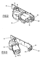
- a motorized device actuation which, in the embodiment shown, includes a geared motor assembly 10 carried by a fitting 12, itself fixed to the leaf by any appropriate means ( Figures 2 and 3).
- the gear motor constituting an actuator is articulated on the fitting around an axis 14 and it has at its end opposite to where it is located the joint, a stirrup 16 delimiting a bolt 18 consisting of a tab in which is formed a notch 19.
- the fitting 12 supporting the gear motor is folded at its end in 20 to receive the part forming a keeper 22 of a locking mechanism of the type used in seat belt buckles for vehicles or any other mechanism fulfilling the same function.
- the mechanism constituting this strike is known in itself and will therefore not be described in detail. A description such a mechanism can be found especially in documents DE-A-19 38 380, SE-A-389798, DE-27 54 389, WO-80/00404, FR-A-2.349.296, FR-A-2.379.995, FR-A-2.509.969.
- this loop comprises a locking member intended to cooperate with the bolt 18, coming to engage in the notch 19 provided in this bolt, as well as a control button 24 allowing release the blocking member and release the bolt, a spring also being provided in the keeper to push back the bolt when it has been released.
- These mechanisms are designed to be able to withstand relatively large tensile forces exerted between the bolt and the strike and so that the effort necessary to press the control key and release the bolt remains weak and preferably substantially constant.
- the actuation device is completed, from known manner, by two arms hinged together at 27 and the first 26 of which is integral with the output shaft 15 of the gearmotor, while the other 28 is articulated at 29 on a fitting 30 itself fixed on the pillar.
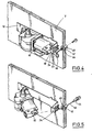
- Figures 4 and 5 show a part of an actuation device of the same general type described with reference to FIGS. 1 to 3, but comprising a further development.
- This is how the leaf is provided with a lock 40 arranged in the vicinity of the locking mechanism, this lock 40 being able to be operated by a key, from the outside of the leaf V.
- the lock 40 comprises a body 42 fixed on the leaf and a barrel 44 connected by a cable 46 to the control button 24 of the locking mechanism.
- the lock used is of the type known in itself, in which in the closed position the barrel is secured to the lock body, while in position this barrel is released from the body and can be extract, as shown in Figure 5.
- Figures 6 to 8 show another mode for producing a device according to the invention.
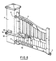
- a portal comprising a movable leaf V articulated by hinges G on a P pillar.
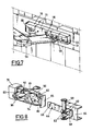
- the actuation device the overall design is known, includes support 50 fixed on pillar P, an arm 52 articulated on this support around an axis 54, an articulated bent arm 56, of a hand, in 57 on arm 52 and on the other hand on a yoke 58 via an axis, materialized by a pin 59 (figure 7).
- the joint 57 between the arm 52 and the arm angled 56 includes a type of drive mechanism toothed wheel and worm, the latter being driven in rotation from an electric motor, not shown in the drawing, housed for example in the support 50 or in the arm 52.
- Such drive means constitute an actuator. They are also known and will therefore not be described in detail.
- the screed preferably comprises, a second set of orifices 62, in which the pin can be received in order to move the location of the axis of articulation between the arm 56 and the yoke.
- the yoke 58 is carried by a slide 64 having a U shape and which is integral with a tab 66 constituting a bolt, this bolt comprising in the vicinity of its free end a notch or a hole 68.
- the slide 64 is received in a slide 70 fixed on the leaf.
- This slide is formed by a profile of rectangular section with the face 71 directed towards the actuating device is indented at 72 so to allow passage and movement of the yoke 58.
- This notch 72 opens at the end of the slide farthest from the pillar, as can be seen in figure 7.
- a locking mechanism (Figure 8), which as in the embodiment previous, is of the type used in the loops of seat belts for vehicles.
- This strike 74 is fixed by means of a screw 76 and blocked and centered by a part 78 cut and folded from the slide 70.
- the keeper 74 is completed by a stirrup-shaped part 80, of which the two longitudinal branches 81 have at near their ends two folded edges 82 engaging the control button 84 of the mechanism lock.
- the device is completed by a lock 90 of the European barrel type, this lock having a sufficient length to be able to cross the slide and be accessible from the inside and from the outer face of the leaf.
- the lock extends in the space left free between the keeper 74 of the lock and the caliper 83 soul 80, and it's arranged in such a way that its movable bit 92, activated when the key and barrel are rotated can come into contact with the core 83 of the stirrup 80, push it back and move the command 84.
- this second set of articulation holes is chosen to take into account the games that are caught when the device is in a bracing position, the leaf being closed.
- Figures 9 to 12 show a variant to the arrangement which has just been described of an axis of articulation can occupy two positions.
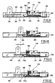
- the means making it possible to take into account the games that are released during uncoupling of the actuating device are incorporated in the locking mechanism with bolt and strike.
- the parts corresponding to those shown in the figures 7 and 8 are designated in Figures 9 to 12 by the same reference numbers, increased by 100.
- Keep 174 is carried by a support 175 itself fixed on the slide 170.
- This strike includes a control button 184 and a locking member 173 intended to cooperate with hole 168.
- a second blocking member consisting of a metal tab 200 elastically deformable, having at one end a hook 202, intended to cooperate with the second hole 169 of the bolt, and at its opposite end a tab 204 intended to cooperate with the bit of a lock, for elsewhere optional.
- This lock 190 has been shown in phantom in Figure 9.
- the tongue 200 also has two legs lateral 206 extending substantially perpendicularly compared to his plan and which are received in two side housings 208 of the control button 184.
- the tab 200 is thus made integral with the touch of control, in translation in a parallel direction to the direction of movement of the bolt relative to the spoils.
- This uncoupling corresponds to the situation represented in FIG. 12 where the control key 184 has been moved to the right by considering the drawing, at the same time as the tongue 200, which has the effect of erasing the hook 202 by an effect of ramp intervening between the front edge 175 a of the support 175 and an inclined part 201 of the tongue 200.
- the bolt is then released from one or the other of the two locking members and can move to the left considering the drawing to then be released from the slide, as already explained in connection with FIGS. 6 to 8.
- Pressing the control button 184 can be done manually by acting directly on this key, or by means of lock 190 whose the angularly movable blade acts on the tab end 204 of the tongue.
- the invention can be applied to any device for actuating gates or the like, whatever the type of actuator used, hydraulic or electro-mechanical and whatever the kinematics means connecting the portal to the fixed structure on which he rode.
Landscapes
- Lock And Its Accessories (AREA)
Description
- le dispositif d'actionnement, du type comprenant un moto-réducteur articulé au voisinage d'une de ses extrémités sur une ferrure fixée sur le panneau mobile, est caractérisé en ce que le mécanisme de verrouillage est disposé entre l'autre extrémité du moto-réducteur et l'extrémité adjacente de la ferrure ;
- le dispositif d'actionnement, du type comprenant au moins un bras articulé sur la structure fixe et sur un coulisseau reçu dans une glissière fixée sur le panneau mobile, est caractérisé en ce que le mécanisme de verrouillage à gâche et pêne est disposé entre le coulisseau et la glissière ;
- la glissière porte la gâche et le coulisseau porte le pêne.
- la serrure est du type comprenant un corps fixe et un canon amovible, relié par un lien à l'organe de commande de la gâche ;
- la serrure est disposée au voisinage de la gâche et traverse la glissière et le panneau mobile, cette serrure comportant un panneton mobile coopérant avec un organe intermédiaire relié à l'organe de commande de la gâche ;
- l'organe intermédiaire est un étrier muni de deux rebords en prise sur l'organe de commande et dont l'âme coopère avec le panneton de la serrure, cette dernière s'étendant dans l'espace délimité entre ladite âme et la gâche.
- la figure 1 représente de façon schématique un portail équipé d'un dispositif d'actionnement suivant un premier mode de réalisation de l'invention ;
- la figure 2 est une vue en perspective à plus grande échelle d'une partie du dispositif de la figure 1 ;
- la figure 3 est une vue analogue à celle de la figure 2 représentant le dispositif en position désaccouplée ;
- les figures 4 et 5 sont des vues analogues à celles des figures 2 et 3, d'une variante de réalisation ;
- la figure 6 représente un portail équipé d'un dispositif d'actionnement d'un type différent, perfectionné selon l'invention ;
- la figure 7 est une vue en perspective à plus grande échelle d'une partie du dispositif de la figure 6 ;
- la figure 8 est une vue en perspective avec arrachement montrant le dispositif en position désaccouplée ; et
- les figures 9 à 12 sont des vues en coupe représentant dans quatre positions différentes une variante de réalisation.
- le désaccouplement du dispositif d'actionnement est rendu extrêmement facile, par l'utilisation d'un mécanisme de verrouillage et de déverrouillage dans lequel l'effort nécessaire lors de la manoeuvre de déverrouillage est faible et pratiquement indépendant de l'effort d'arc-boutement exercé par le dispositif ;
- ce résultat est obtenu en utilisant un mécanisme qui est connu par ailleurs dans des applications tout à fait différentes, et qui, étant fabriqué en grande série représente un coût relativement faible. L'adaptation du dispositif, pour l'incorporation d'un tel mécanisme est relativement simple et peu coûteuse ;
- lorsque le mécanisme de verrouillage est associé à une serrure accessible soit de l'extérieur, soit de l'intérieur et de l'extérieur du panneau mobile, un avantage supplémentaire important est obtenu puisque l'utilisateur peut très facilement désaccoupler le dispositif d'actionnement aussi bien de l'intérieur que de l'extérieur du portail ;
- dans les modes de réalisation des figures 6 à 8 et des figures 9 à 12, le dispositif d'actionnement peut être replacé en position d'utilisation et en position de blocage du portail, du fait de la prise en compte des jeux qui sont libérés lors du désaccouplement et qui sont habituellement résorbés par l'effort d'arc-boutement exercé en position de fermeture. Le coulisseau étant simplement réintroduit dans la glissière, l'utilisateur peut ensuite en étant à l'extérieur du portail, et en refermant ce dernier, provoquer le reverrouillage du pêne, sans avoir à agir directement sur le mécanisme.
Claims (19)
- Dispositif d'actionnement d'un panneau mobile de fermeture (V), articulé sur une structure fixe (P), ce dispositif d'actionnement étant disposé entre la structure fixe et le panneau mobile et comprenant au moins un actionneur (10) et au moins deux articulations (15, 27, 29 ; 54, 57, 59), des moyens étant prévus pour pouvoir désaccoupler deux éléments du dispositif d'actionnement et libérer ainsi le panneau mobile, en cas de dysfonctionnement, caractérisé en ce que lesdits moyens comprennent un mécanisme de verrouillage (18, 22 ; 66, 74) du type comprenant une gâche (22 ; 74) portée par l'un des éléments et un pêne (18 ; 66) porté par l'autre élément, la gâche comprenant un organe de commande permettant de libérer le pêne, la force nécessaire pour manoeuvrer l'organe de commande étant beaucoup plus faible que et sensiblement indépendante de l'effort d'arc boutement exercé par l'actionneur entre le pêne et la gâche.
- Dispositif d'actionnement suivant la revendication 1, caractérisé en ce que le mécanisme de verrouillage comprend une gâche (22 ; 74) pourvue d'une touche de commande (24 ; 84) du type de celles utilisées dans les boucles de ceintures ou sangles de sécurité équipant les véhicules.
- Dispositif d'actionnement suivant l'une quelconque des revendications 1 et 2, du type comprenant un moto-réducteur (10) articulé au voisinage d'une de ses extrémités autour d'un axe (14), sur une ferrure (12) fixée sur le panneau mobile (V), caractérisé en ce que le mécanisme de verrouillage (18, 22) est disposé entre l'autre extrémité du moto-réducteur (10) et l'extrémité adjacente (20) de la ferrure (12).
- Dispositif d'actionnement suivant la revendication 3, caractérisé en ce que la ferrure (12) est repliée à son extrémité (en 20) pour supporter une partie (22) du mécanisme de verrouillage.
- Dispositif d'actionnement suivant la revendication 4, caractérisé en ce que la ferrure (12) porte la gâche (22) et le moto-réducteur (10) porte le pêne (18).
- Dispositif d'actionnement suivant l'une quelconque des revendications 1 et 2, du type comprenant au moins un bras (52, 56) articulé sur la structure fixe (P) et sur un coulisseau (64) reçu dans une glissière (70) fixée sur le panneau mobile (V), caractérisé en ce que le mécanisme de verrouillage à gâche (74) et pêne (66) est disposé entre le coulisseau (64) et la glissière (70).
- Dispositif d'actionnement suivant la revendication 6, caractérisé en ce que la glissière (70) porte la gâche (74) et le coulisseau (64) porte le pêne (66).
- Dispositif d'actionnement suivant l'une quelconque des revendications 1 à 7, caractérisé en ce qu'il comprend des moyens de compensation des jeux libérés lors de son désaccouplement.
- Dispositif d'actionnement suivant la revendication 8, caractérisé en ce que lesdits moyens sont intégrés à l'une des articulations du dispositif et sont adaptés pour pouvoir modifier la position de l'axe de cette articulation.
- Dispositif d'actionnement suivant la revendication 9, combinée à l'une des revendications 6 et 7, caractérisé en ce que l'articulation du bras (56) sur le coulisseau (64) est réalisé au moyen d'une pièce d'articulation (59) pouvant occuper au moins deux positions (60, 62).
- Dispositif d'actionnement suivant la revendication 8, caractérisé en ce que lesdits moyens (169, 202) sont incorporés au mécanisme à gâche et pêne.
- Dispositif d'actionnement suivant la revendication 11, caractérisé en ce que lesdits moyens comprennent un organe supplémentaire de blocage (202), coopérant avec le pêne de façon à bloquer ce dernier dans une position différente de celle dans laquelle il est normalement verrouillé, cet organe supplémentaire de verrouillage étant monté effaçable pour pouvoir libérer le pêne.
- Dispositif d'actionnement suivant la revendication 12, caractérisé en ce que le pêne (166) comporte deux trous ou encoches (168, 169), le premier (168) adapté pour coopérer avec la gâche et le second (169) adapté pour coopérer avec l'extrémité (202) d'une languette (200) déformable élastiquement, cette languette étant mobile en translation, en même temps que l'organe (184) de commande de la gâche, et coopérant avec une surface d'appui fixe (175a), pour être effacée et libérer le pêne, lorsque l'organe (184) de commande de la gâche est actionné dans le sens du déverrouillage.
- Dispositif d'actionnement suivant la revendication 13 limitée à sa combinaison avec l'une des revendications 6 et 7, caractérisé en ce que la languette (200) est placée entre la gâche (174, 175) et le fond de la glissière (170) et comporte deux pattes latérales rabattues (206), reçues dans des logements (208) de l'organe de commande (184) de la gâche.
- Dispositif d'actionnement suivant l'une quelconque des revendications 1 à 14, caractérisé en ce qu'il comprend une serrure (40 ; 90 ; 190) accessible au moins de l'extérieur du panneau mobile (V) et qui est adaptée pour pouvoir agir sur l'organe de commande (24 ; 74 ; 174) du mécanisme de verrouillage de façon à libérer le pêne de la gâche.
- Dispositif d'actionnement suivant la revendication 15, caractérisé en ce que la serrure (40) est du type comprenant un corps (42) fixe et un canon amovible (44), relié par un lien (46) à l'organe de commande (24) de la gâche.
- Dispositif d'actionnement suivant la revendication 15, combinée à l'une quelconque des revendications 6 à 14, caractérisé en ce que la serrure (90 ; 190) est disposée au voisinage de la gâche (74) et traverse la glissière (70 ; 170) et le panneau mobile (V), cette serrure comportant un panneton mobile (92) coopérant avec un organe intermédiaire (80 ; 200) relié à l'organe de commande (84 ; 184) de la gâche.
- Dispositif d'actionnement suivant la revendication 17, caractérisé en ce que l'organe intermédiaire est un étrier (80) muni de deux rebords (82) en prise sur l'organe de commande (84) et dont l'âme (83) coopère avec le panneton (92) de la serrure, cette dernière s'étendant dans l'espace délimité entre ladite âme et la gâche.
- Dispositif d'actionnement suivant l'une des revendications 17, 18 combinée à la revendication 14, caractérisé en ce que la languette (200) comporte à son extrémité opposée à celle qui coopère avec le pêne, une patte (204) avec laquelle peut coopérer le panneton mobile de la serrure (190), pour actionner la languette et l'organe de commande de la gâche.
Applications Claiming Priority (2)
| Application Number | Priority Date | Filing Date | Title |
|---|---|---|---|
| FR9507447A FR2735516B1 (fr) | 1995-06-16 | 1995-06-16 | Dispositif d'actionnement pour portail ou autre panneau de fermeture |
| FR9507447 | 1995-06-16 |
Publications (2)
| Publication Number | Publication Date |
|---|---|
| EP0748916A1 EP0748916A1 (fr) | 1996-12-18 |
| EP0748916B1 true EP0748916B1 (fr) | 2003-09-03 |
Family
ID=9480244
Family Applications (1)
| Application Number | Title | Priority Date | Filing Date |
|---|---|---|---|
| EP96420200A Expired - Lifetime EP0748916B1 (fr) | 1995-06-16 | 1996-06-07 | Dispositif d'actionnement pour portail ou autre panneau de fermeture |
Country Status (5)
| Country | Link |
|---|---|
| EP (1) | EP0748916B1 (fr) |
| CA (1) | CA2178797A1 (fr) |
| DE (1) | DE69629759T2 (fr) |
| ES (1) | ES2205007T3 (fr) |
| FR (1) | FR2735516B1 (fr) |
Families Citing this family (8)
| Publication number | Priority date | Publication date | Assignee | Title |
|---|---|---|---|---|
| FR2757560B1 (fr) * | 1996-12-23 | 1999-01-22 | Le Brun Yanck | Dispositif de debrayage a distance d'un ensemble d'entrainement automatise d'un vantail coulissant tel qu'un portail |
| IT236446Y1 (it) * | 1997-02-05 | 2000-08-17 | Automatica Casali S R L | Dispositivo di svincolo manuale di un cancello da un rispettivoattuatore motorizzato |
| FR2814771B1 (fr) * | 2000-09-29 | 2004-07-09 | Peugeot Citroen Automobiles Sa | Dispositif d'assistance pour l'ouverture et la fermeture d'une porte de vehicule automobile |
| FR2901302B1 (fr) * | 2006-05-18 | 2008-07-25 | Clotures Le Brun Sarl | Dispositif d'ouverture partielle a distance d'un actionneur d'une porte d'un portail battant |
| FR2919331B1 (fr) * | 2007-07-27 | 2009-09-25 | Europorte Sarl | Dispositif d'articulation et de securite pour ouverture fermeture de battants de portes, portails et similaires. |
| ITRM20080039U1 (it) * | 2008-03-10 | 2009-09-11 | Cebi Srl | Dispositivo di svincolo meccanico ad azionamento manuale per attuatori elettromeccanici o oleodinamici di tipo a braccio utilizzati per la motorizzazione di serramenti ad ante battenti |
| IT1403000B1 (it) * | 2010-11-18 | 2013-09-27 | Came Group S P A | Serratura per cancello. |
| DE102010052374B4 (de) * | 2010-11-24 | 2014-05-15 | Belfox Torautomatik Produktions- U. Vertriebs-Gmbh | Torantrieb mit Linearführung |
Family Cites Families (5)
| Publication number | Priority date | Publication date | Assignee | Title |
|---|---|---|---|---|
| DE858262C (de) * | 1951-04-14 | 1952-12-04 | Duesseldorfer Waggonfabrik Ag | Mechanische Betaetigung von Dreh-, Falt- oder Schwingtueren fuer Schienen- oder Strassenfahrzeuge |
| US3235246A (en) * | 1964-01-15 | 1966-02-15 | Scient Products Inc | Safety quick-release coupling device |
| US3443339A (en) * | 1967-03-07 | 1969-05-13 | Chamberlain Mfg Corp | Release mechanism for garage door connecting arm |
| FR2469543A1 (fr) * | 1979-11-15 | 1981-05-22 | Antares | Dispositif de manoeuvre de portail |
| FR2569222B1 (fr) * | 1984-08-17 | 1989-06-16 | Sapa Sarl | Dispositif d'ouverture et de fermeture automatique des portails |
-
1995
- 1995-06-16 FR FR9507447A patent/FR2735516B1/fr not_active Expired - Fee Related
-
1996
- 1996-06-07 EP EP96420200A patent/EP0748916B1/fr not_active Expired - Lifetime
- 1996-06-07 ES ES96420200T patent/ES2205007T3/es not_active Expired - Lifetime
- 1996-06-07 DE DE69629759T patent/DE69629759T2/de not_active Expired - Fee Related
- 1996-06-11 CA CA002178797A patent/CA2178797A1/fr not_active Abandoned
Also Published As
| Publication number | Publication date |
|---|---|
| CA2178797A1 (fr) | 1996-12-17 |
| ES2205007T3 (es) | 2004-05-01 |
| DE69629759T2 (de) | 2004-07-01 |
| EP0748916A1 (fr) | 1996-12-18 |
| FR2735516A1 (fr) | 1996-12-20 |
| DE69629759D1 (de) | 2003-10-09 |
| FR2735516B1 (fr) | 1997-08-14 |
Similar Documents
| Publication | Publication Date | Title |
|---|---|---|
| EP0959206B1 (fr) | Serrure de porte de véhicule automobile à condamnation électrique | |
| EP2663705B1 (fr) | Poignee d'ouvrant de vehicule comprenant une partie de prehension | |
| FR2737906A1 (fr) | Fermeture de vehicule automobile | |
| FR2513298A1 (fr) | Dispositif pour manoeuvrer des serrures de portiere d'un vehicule automobile | |
| EP0989264A1 (fr) | Serrure électrique perfectionnée pour portière de vehicule automobile | |
| EP1334865A2 (fr) | Dispositif de calage vertical et automatique d'un siège de véhicule | |
| EP0190976B1 (fr) | Mécanisme d'assistance à la fermeture d'une porte d'un véhicule automobile | |
| FR2623779A1 (fr) | Dispositif d'ouverture/fermeture | |
| FR2489405A1 (fr) | Porte du type coulissant pour un vehicule | |
| FR2753741A1 (fr) | Fermeture de portiere de vehicule automobile avec systeme de verrouillage protege-enfants | |
| EP2611978A2 (fr) | Poignee d'ouvrant de vehicule comprenant une masse inertielle | |
| EP1030014A1 (fr) | Serrure en trois parties, pour ouvrant de véhicule automobile | |
| FR2775717A1 (fr) | Dispositif d'ouverture/fermeture d'un ouvrant, notamment pour vehicule automobile | |
| EP0669234A1 (fr) | Antivol de direction de véhicule automobile comportant des moyens de blocage du pêne de verrouillage | |
| EP0748916A1 (fr) | Dispositif d'actionnement pour portail ou autre panneau de fermeture | |
| EP4177425B1 (fr) | Dispositif de commande d'ouverture extérieure d'un ouvrant de véhicule automobile | |
| EP1738043A2 (fr) | Cle a tige escamotable comportant des moyens d"entrainement de la tige vers une position deployee | |
| EP0989265B1 (fr) | Serrure simplifiée pour portière de vèhicule automobile | |
| EP2045420A1 (fr) | Système de poignée notamment de crémone, destiné à être implanté sur une face externe de porte, telle qu'une porte de camion frigorifique | |
| FR2473100A1 (fr) | Dispositif pour ouvrir la porte arriere d'un vehicule automobile | |
| EP0906997A1 (fr) | Dispositif de verrouillage comportant un objet de transmission commandé par came | |
| EP0102263B1 (fr) | Serrure à commande électrique pour portière de véhicule automobile | |
| EP0989266A1 (fr) | Serrure à décondamnation automatique à l'ouverture | |
| EP1607261A1 (fr) | Trappe obturatrice pour une carrosserie d'un véhicule automobile et véhicule automobile comportant une telle trappe | |
| FR2794791A1 (fr) | Perfectionnement a une serrure electrique, notamment pour portiere de vehicule automobile |
Legal Events
| Date | Code | Title | Description |
|---|---|---|---|
| PUAI | Public reference made under article 153(3) epc to a published international application that has entered the european phase |
Free format text: ORIGINAL CODE: 0009012 |
|
| AK | Designated contracting states |
Kind code of ref document: A1 Designated state(s): BE DE ES IT |
|
| 17P | Request for examination filed |
Effective date: 19970605 |
|
| 17Q | First examination report despatched |
Effective date: 19990219 |
|
| GRAH | Despatch of communication of intention to grant a patent |
Free format text: ORIGINAL CODE: EPIDOS IGRA |
|
| GRAS | Grant fee paid |
Free format text: ORIGINAL CODE: EPIDOSNIGR3 |
|
| GRAA | (expected) grant |
Free format text: ORIGINAL CODE: 0009210 |
|
| AK | Designated contracting states |
Kind code of ref document: B1 Designated state(s): BE DE ES IT |
|
| REF | Corresponds to: |
Ref document number: 69629759 Country of ref document: DE Date of ref document: 20031009 Kind code of ref document: P |
|
| REG | Reference to a national code |
Ref country code: ES Ref legal event code: FG2A Ref document number: 2205007 Country of ref document: ES Kind code of ref document: T3 |
|
| PG25 | Lapsed in a contracting state [announced via postgrant information from national office to epo] |
Ref country code: BE Free format text: LAPSE BECAUSE OF NON-PAYMENT OF DUE FEES Effective date: 20040630 |
|
| PLBE | No opposition filed within time limit |
Free format text: ORIGINAL CODE: 0009261 |
|
| STAA | Information on the status of an ep patent application or granted ep patent |
Free format text: STATUS: NO OPPOSITION FILED WITHIN TIME LIMIT |
|
| 26N | No opposition filed |
Effective date: 20040604 |
|
| BERE | Be: lapsed |
Owner name: *SIMU Effective date: 20040630 |
|
| PGFP | Annual fee paid to national office [announced via postgrant information from national office to epo] |
Ref country code: ES Payment date: 20080620 Year of fee payment: 13 |
|
| PGFP | Annual fee paid to national office [announced via postgrant information from national office to epo] |
Ref country code: DE Payment date: 20080613 Year of fee payment: 13 |
|
| PGFP | Annual fee paid to national office [announced via postgrant information from national office to epo] |
Ref country code: IT Payment date: 20080626 Year of fee payment: 13 |
|
| PG25 | Lapsed in a contracting state [announced via postgrant information from national office to epo] |
Ref country code: DE Free format text: LAPSE BECAUSE OF NON-PAYMENT OF DUE FEES Effective date: 20100101 |
|
| REG | Reference to a national code |
Ref country code: ES Ref legal event code: FD2A Effective date: 20090608 |
|
| PG25 | Lapsed in a contracting state [announced via postgrant information from national office to epo] |
Ref country code: ES Free format text: LAPSE BECAUSE OF NON-PAYMENT OF DUE FEES Effective date: 20090608 |
|
| PG25 | Lapsed in a contracting state [announced via postgrant information from national office to epo] |
Ref country code: IT Free format text: LAPSE BECAUSE OF NON-PAYMENT OF DUE FEES Effective date: 20090607 |