EP0748704A1 - Method of extruding two or more materials - Google Patents
Method of extruding two or more materials Download PDFInfo
- Publication number
- EP0748704A1 EP0748704A1 EP96300570A EP96300570A EP0748704A1 EP 0748704 A1 EP0748704 A1 EP 0748704A1 EP 96300570 A EP96300570 A EP 96300570A EP 96300570 A EP96300570 A EP 96300570A EP 0748704 A1 EP0748704 A1 EP 0748704A1
- Authority
- EP
- European Patent Office
- Prior art keywords
- materials
- cooling
- ornamented
- extruding
- bond
- Prior art date
- Legal status (The legal status is an assumption and is not a legal conclusion. Google has not performed a legal analysis and makes no representation as to the accuracy of the status listed.)
- Granted
Links
Images
Classifications
-
- B—PERFORMING OPERATIONS; TRANSPORTING
- B32—LAYERED PRODUCTS
- B32B—LAYERED PRODUCTS, i.e. PRODUCTS BUILT-UP OF STRATA OF FLAT OR NON-FLAT, e.g. CELLULAR OR HONEYCOMB, FORM
- B32B37/00—Methods or apparatus for laminating, e.g. by curing or by ultrasonic bonding
- B32B37/14—Methods or apparatus for laminating, e.g. by curing or by ultrasonic bonding characterised by the properties of the layers
- B32B37/15—Methods or apparatus for laminating, e.g. by curing or by ultrasonic bonding characterised by the properties of the layers with at least one layer being manufactured and immediately laminated before reaching its stable state, e.g. in which a layer is extruded and laminated while in semi-molten state
- B32B37/153—Methods or apparatus for laminating, e.g. by curing or by ultrasonic bonding characterised by the properties of the layers with at least one layer being manufactured and immediately laminated before reaching its stable state, e.g. in which a layer is extruded and laminated while in semi-molten state at least one layer is extruded and immediately laminated while in semi-molten state
-
- A—HUMAN NECESSITIES
- A47—FURNITURE; DOMESTIC ARTICLES OR APPLIANCES; COFFEE MILLS; SPICE MILLS; SUCTION CLEANERS IN GENERAL
- A47G—HOUSEHOLD OR TABLE EQUIPMENT
- A47G1/00—Mirrors; Picture frames or the like, e.g. provided with heating, lighting or ventilating means
- A47G1/06—Picture frames
- A47G1/0616—Ornamental frames, e.g. with illumination, speakers or decorative features
- A47G1/0627—Ornamental frames, e.g. with illumination, speakers or decorative features with decorative strips or layers on the frame members
-
- B—PERFORMING OPERATIONS; TRANSPORTING
- B29—WORKING OF PLASTICS; WORKING OF SUBSTANCES IN A PLASTIC STATE IN GENERAL
- B29C—SHAPING OR JOINING OF PLASTICS; SHAPING OF MATERIAL IN A PLASTIC STATE, NOT OTHERWISE PROVIDED FOR; AFTER-TREATMENT OF THE SHAPED PRODUCTS, e.g. REPAIRING
- B29C43/00—Compression moulding, i.e. applying external pressure to flow the moulding material; Apparatus therefor
- B29C43/22—Compression moulding, i.e. applying external pressure to flow the moulding material; Apparatus therefor of articles of indefinite length
- B29C43/222—Compression moulding, i.e. applying external pressure to flow the moulding material; Apparatus therefor of articles of indefinite length characterised by the shape of the surface
-
- B—PERFORMING OPERATIONS; TRANSPORTING
- B29—WORKING OF PLASTICS; WORKING OF SUBSTANCES IN A PLASTIC STATE IN GENERAL
- B29C—SHAPING OR JOINING OF PLASTICS; SHAPING OF MATERIAL IN A PLASTIC STATE, NOT OTHERWISE PROVIDED FOR; AFTER-TREATMENT OF THE SHAPED PRODUCTS, e.g. REPAIRING
- B29C48/00—Extrusion moulding, i.e. expressing the moulding material through a die or nozzle which imparts the desired form; Apparatus therefor
- B29C48/03—Extrusion moulding, i.e. expressing the moulding material through a die or nozzle which imparts the desired form; Apparatus therefor characterised by the shape of the extruded material at extrusion
- B29C48/07—Flat, e.g. panels
- B29C48/08—Flat, e.g. panels flexible, e.g. films
-
- B—PERFORMING OPERATIONS; TRANSPORTING
- B29—WORKING OF PLASTICS; WORKING OF SUBSTANCES IN A PLASTIC STATE IN GENERAL
- B29C—SHAPING OR JOINING OF PLASTICS; SHAPING OF MATERIAL IN A PLASTIC STATE, NOT OTHERWISE PROVIDED FOR; AFTER-TREATMENT OF THE SHAPED PRODUCTS, e.g. REPAIRING
- B29C48/00—Extrusion moulding, i.e. expressing the moulding material through a die or nozzle which imparts the desired form; Apparatus therefor
- B29C48/03—Extrusion moulding, i.e. expressing the moulding material through a die or nozzle which imparts the desired form; Apparatus therefor characterised by the shape of the extruded material at extrusion
- B29C48/13—Articles with a cross-section varying in the longitudinal direction, e.g. corrugated pipes
-
- B—PERFORMING OPERATIONS; TRANSPORTING
- B29—WORKING OF PLASTICS; WORKING OF SUBSTANCES IN A PLASTIC STATE IN GENERAL
- B29C—SHAPING OR JOINING OF PLASTICS; SHAPING OF MATERIAL IN A PLASTIC STATE, NOT OTHERWISE PROVIDED FOR; AFTER-TREATMENT OF THE SHAPED PRODUCTS, e.g. REPAIRING
- B29C48/00—Extrusion moulding, i.e. expressing the moulding material through a die or nozzle which imparts the desired form; Apparatus therefor
- B29C48/15—Extrusion moulding, i.e. expressing the moulding material through a die or nozzle which imparts the desired form; Apparatus therefor incorporating preformed parts or layers, e.g. extrusion moulding around inserts
- B29C48/154—Coating solid articles, i.e. non-hollow articles
-
- B—PERFORMING OPERATIONS; TRANSPORTING
- B44—DECORATIVE ARTS
- B44C—PRODUCING DECORATIVE EFFECTS; MOSAICS; TARSIA WORK; PAPERHANGING
- B44C5/00—Processes for producing special ornamental bodies
-
- B—PERFORMING OPERATIONS; TRANSPORTING
- B29—WORKING OF PLASTICS; WORKING OF SUBSTANCES IN A PLASTIC STATE IN GENERAL
- B29C—SHAPING OR JOINING OF PLASTICS; SHAPING OF MATERIAL IN A PLASTIC STATE, NOT OTHERWISE PROVIDED FOR; AFTER-TREATMENT OF THE SHAPED PRODUCTS, e.g. REPAIRING
- B29C59/00—Surface shaping of articles, e.g. embossing; Apparatus therefor
- B29C59/02—Surface shaping of articles, e.g. embossing; Apparatus therefor by mechanical means, e.g. pressing
- B29C59/04—Surface shaping of articles, e.g. embossing; Apparatus therefor by mechanical means, e.g. pressing using rollers or endless belts
-
- Y—GENERAL TAGGING OF NEW TECHNOLOGICAL DEVELOPMENTS; GENERAL TAGGING OF CROSS-SECTIONAL TECHNOLOGIES SPANNING OVER SEVERAL SECTIONS OF THE IPC; TECHNICAL SUBJECTS COVERED BY FORMER USPC CROSS-REFERENCE ART COLLECTIONS [XRACs] AND DIGESTS
- Y10—TECHNICAL SUBJECTS COVERED BY FORMER USPC
- Y10T—TECHNICAL SUBJECTS COVERED BY FORMER US CLASSIFICATION
- Y10T428/00—Stock material or miscellaneous articles
- Y10T428/24—Structurally defined web or sheet [e.g., overall dimension, etc.]
- Y10T428/24479—Structurally defined web or sheet [e.g., overall dimension, etc.] including variation in thickness
- Y10T428/24496—Foamed or cellular component
Definitions
- the present invention relates to a method of extruding two or more materials, and especially to a method of manufacturing ornamented elongate members, in particular for use as picture members or dado rails for interior decoration.
- Such members are traditionally made of wood or plaster, but these are now very expensive. In order to reduce the cost, it is known to use simple plastics extrusions, which are considerably cheaper to produce, but these cannot easily produce detailed ornamentation.
- Other known extrusions techniques using two or more materials are not suitable for forming ornamented members, which require a firmly bonded structure, and the ability to be decorated by mechanical treatment. For example, co-extrusion of two materials forms a firmly bonded structure, but as the materials tend to solidify at the same rate, it is not possible to shape one material to form ornamentation by applying pressure, as the other material would not be sufficiently solid to withstand the process.
- Sequential extrusion of materials is known, where a first material is becoming solid before a second is applied. Such sequential extrusion is generally used for seals, and either a firm bond is not formed between the materials, or pressure cannot be applied to the second material to form ornamentation, as the first material is not sufficiently solid.
- GB-A-2 276 318 Another method of producing ornamented elongate members using an extrusion process is shown in GB-A-2 276 318, where an extruded plastics material is ornamented by applying a solvent-based wood paste.
- the two materials form a surprisingly good bond, and the wood paste can be shaped to form ornamentation.
- this process has several disadvantages. Most notably, the finished product takes a substantial time to dry, of the order of several hours, and has a tendency to bow significantly. Further, the extruded material must be cut into appropriate lengths before application of the wood paste.
- a method of manufacturing an ornamented elongate member comprises the steps of:
- This method provides a sequential extrusion method in which the materials are firmly bonded together. Furthermore, as the first material is substantially solid before extrusion of the second material onto it, the second material may be mechanically treated to produce the ornamentation without affecting the first material. Cooling times are of the order of a few minutes, so are substantially reduced in comparison with the wood paste product.
- the first material is preferably a thermoplastic material, and the temperatures of the materials are arranged to melt the surface of the first material, enabling a bond to be formed between the materials.
- the process may then include the step of pre-heating the first thermoplastic material after cooling and prior to the second extrusion, to aid the bonding mechanism.
- the first material may be a thermosetting material, and chemical treatment used to provide the change in the surface of the first material, enabling a bond to be formed between the two materials.
- the temperatures of the materials may be controlled so that extrusion of the second material causes the change in the surface of the first material to form the bond.
- the method may include a further step of biasing the cooling of the first and second materials to counteract any bowing of the materials thereby forming a firmly bonded and substantially straight structure.
- the first and second materials may be stressed, in combination with cooling, to counteract the bowing and form a firmly bonded, substantially straight structure. In either case, bowing is more easily counteracted than with the wood paste method.
- the second material may be extruded such that it covers all or a part of the surface of the first material.
- the materials to be extruded must be compatible, that is to say they must be capable of bonding together.
- the materials may each be plastics materials.
- the first is preferably a thermoplastic material, while the second may be a thermoplastic or a thermosetting material.
- the first material is preferably blown polystyrene.
- the second material may then be styrene.
- both materials could be thermoplastic rubbers. If the second material is compatible, then a third material may be sequentially extruded onto a surface of the second material.
- the method may include an additional step of cutting the firmly bonded substantially rigid structure into lengths, which are suitable for use as frame members or the like.
- the first material may be cut into appropriate lengths before application of the second material.
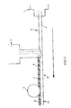
- Figure 1 shows apparatus for producing ornamented elongate members, such as picture frame members.
- the apparatus consists of a first extruder 1, a second extruder 2 and a pattern wheel 3.
- Means (not shown) are provided for conveying the extruded materials through the apparatus.
- a first core thermoplastic material 4 in this case blown polystyrene, is extruded from the first extruder 1, and is conveyed along path 5 to the second extruder 2, during which time the material cools to form a substantially solid, rigid core for the frame member.
- the second extruder 2 extrudes a second thermoplastic material 6, in this case styrene, as a decorative material along the length of the core material 4.
- the temperature of the decorative material 6 is such as to melt the surface of the first material 4, enabling a firm bond to be formed at the interface 7 between the two materials.
- the core and decorative materials are then fed along path 8, kept at a temperature such that the decorative material remains molten or at least plastic, and under the pattern wheel 3. This shapes the decorative material, forming ornamentation 9.
- the ornamented materials are then fed along path 10, where they are cooled to form a firmly bonded, substantially rigid structure. This structure is then cut into lengths suitable for use as frame members.
- An additional step of pre-heating the surface of the core thermoplastic material 4 which is to be bonded may be introduced in path 5 after cooling has taken place, thereby siding the bonding process.
- the cooling of the ornamented materials along path 10 may be biased in order to prevent any bowing which may occur, and ensures the forming of a firmly bonded, substantially straight and rigid structure.
- the materials may, in combination with cooling, be stressed along this path in such a way to counteract any tendency to bow, thereby forming a firmly bonded, substantially straight and rigid structure.
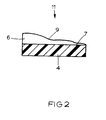
- Figure 2 shows a section through a portion of a frame member 11, comprising the first thermoplastic material 4 bonded along the interface 7 with the second thermoplastic material 6, the second thermoplastic material having ornamentation 9 on its unbonded surface.
- a variety of ornamentation may be produced by simply changing the pattern wheel.
- the materials used are chosen for their suitability for the items being made. While in the embodiment described the materials are blown polystyrene and styrene, it will be appreciated that other combinations are possible. Indeed, as long as the materials are compatible, in that a firm bond is formed between them, any suitable combination can be used.
- the first material may be thermoplastic or thermosetting, as may the second material. Materials other than plastics may also be used.
- the first and second materials in path 8 may be cooled to form a firm bond between them, and a third material extruded onto a surface of the second material.
- the third material may then be shaped, and the first, second and third materials cooled to form a firm bond between the second and third materials, and cut into lengths as previously described. It will be appreciated that a number of layers may be built up in this way, where the second, third etc. layer may cover part or all of the preceding layer, and where one or more layers may be shaped.
- the first material may be a thermosetting material, and chemical treatment applied in path 5, changing the surface of the first material so that a firm bond may be formed between it and the second material.
- a number of layers may be built up in this way.
Abstract
Description
- The present invention relates to a method of extruding two or more materials, and especially to a method of manufacturing ornamented elongate members, in particular for use as picture members or dado rails for interior decoration.
- Such members are traditionally made of wood or plaster, but these are now very expensive. In order to reduce the cost, it is known to use simple plastics extrusions, which are considerably cheaper to produce, but these cannot easily produce detailed ornamentation. Other known extrusions techniques using two or more materials are not suitable for forming ornamented members, which require a firmly bonded structure, and the ability to be decorated by mechanical treatment. For example, co-extrusion of two materials forms a firmly bonded structure, but as the materials tend to solidify at the same rate, it is not possible to shape one material to form ornamentation by applying pressure, as the other material would not be sufficiently solid to withstand the process. Sequential extrusion of materials is known, where a first material is becoming solid before a second is applied. Such sequential extrusion is generally used for seals, and either a firm bond is not formed between the materials, or pressure cannot be applied to the second material to form ornamentation, as the first material is not sufficiently solid.
- Another method of producing ornamented elongate members using an extrusion process is shown in GB-A-2 276 318, where an extruded plastics material is ornamented by applying a solvent-based wood paste. The two materials form a surprisingly good bond, and the wood paste can be shaped to form ornamentation. However, this process has several disadvantages. Most notably, the finished product takes a substantial time to dry, of the order of several hours, and has a tendency to bow significantly. Further, the extruded material must be cut into appropriate lengths before application of the wood paste.
- According to a first aspect of the invention, a method of manufacturing an ornamented elongate member comprises the steps of:
- extruding a first material;
- cooling the first material so that it becomes substantially solid;
- extruding a second material along a surface of the first material, while arranging for the surface of the first material to undergo a change which enables a firm bond to be formed between the materials;
- shaping the second material whilst it is still plastic to produce surface ornamentation; and
- cooling the ornamented first and second materials to form a firmly bonded, substantially rigid structure.
- This method provides a sequential extrusion method in which the materials are firmly bonded together. Furthermore, as the first material is substantially solid before extrusion of the second material onto it, the second material may be mechanically treated to produce the ornamentation without affecting the first material. Cooling times are of the order of a few minutes, so are substantially reduced in comparison with the wood paste product.
- The first material is preferably a thermoplastic material, and the temperatures of the materials are arranged to melt the surface of the first material, enabling a bond to be formed between the materials.
- The process may then include the step of pre-heating the first thermoplastic material after cooling and prior to the second extrusion, to aid the bonding mechanism.
- Alternatively, the first material may be a thermosetting material, and chemical treatment used to provide the change in the surface of the first material, enabling a bond to be formed between the two materials. Alternatively, the temperatures of the materials may be controlled so that extrusion of the second material causes the change in the surface of the first material to form the bond.
- The method may include a further step of biasing the cooling of the first and second materials to counteract any bowing of the materials thereby forming a firmly bonded and substantially straight structure. Alternatively, the first and second materials may be stressed, in combination with cooling, to counteract the bowing and form a firmly bonded, substantially straight structure. In either case, bowing is more easily counteracted than with the wood paste method.
- It will be appreciated that the second material may be extruded such that it covers all or a part of the surface of the first material.
- The materials to be extruded must be compatible, that is to say they must be capable of bonding together. The materials may each be plastics materials. The first is preferably a thermoplastic material, while the second may be a thermoplastic or a thermosetting material. The first material is preferably blown polystyrene. The second material may then be styrene. Alternatively, both materials could be thermoplastic rubbers. If the second material is compatible, then a third material may be sequentially extruded onto a surface of the second material.
- The method may include an additional step of cutting the firmly bonded substantially rigid structure into lengths, which are suitable for use as frame members or the like.
- Alternatively, the first material may be cut into appropriate lengths before application of the second material.
- According to a second aspect of the invention, we provide an ornamented elongate member produced by the method of the first aspect.
- The invention will now be described by way of example only, and with reference to the accompanying drawings, wherein:-
- Figure 1 is a schematic drawing of apparatus for the method used to form ornamented elongate members; and
- Figure 2 is a section through a length of ornamented member.
- Figure 1 shows apparatus for producing ornamented elongate members, such as picture frame members. The apparatus consists of a first extruder 1, a
second extruder 2 and apattern wheel 3. Means (not shown) are provided for conveying the extruded materials through the apparatus. - A first core
thermoplastic material 4, in this case blown polystyrene, is extruded from the first extruder 1, and is conveyed alongpath 5 to thesecond extruder 2, during which time the material cools to form a substantially solid, rigid core for the frame member. Thesecond extruder 2 extrudes a secondthermoplastic material 6, in this case styrene, as a decorative material along the length of thecore material 4. The temperature of thedecorative material 6 is such as to melt the surface of thefirst material 4, enabling a firm bond to be formed at theinterface 7 between the two materials. - The core and decorative materials are then fed along path 8, kept at a temperature such that the decorative material remains molten or at least plastic, and under the
pattern wheel 3. This shapes the decorative material, formingornamentation 9. The ornamented materials are then fed alongpath 10, where they are cooled to form a firmly bonded, substantially rigid structure. This structure is then cut into lengths suitable for use as frame members. - An additional step of pre-heating the surface of the core
thermoplastic material 4 which is to be bonded, may be introduced inpath 5 after cooling has taken place, thereby siding the bonding process. - The cooling of the ornamented materials along
path 10 may be biased in order to prevent any bowing which may occur, and ensures the forming of a firmly bonded, substantially straight and rigid structure. - Alternatively, the materials may, in combination with cooling, be stressed along this path in such a way to counteract any tendency to bow, thereby forming a firmly bonded, substantially straight and rigid structure.
- Figure 2 shows a section through a portion of a
frame member 11, comprising the firstthermoplastic material 4 bonded along theinterface 7 with the secondthermoplastic material 6, the second thermoplasticmaterial having ornamentation 9 on its unbonded surface. A variety of ornamentation may be produced by simply changing the pattern wheel. - The materials used are chosen for their suitability for the items being made. While in the embodiment described the materials are blown polystyrene and styrene, it will be appreciated that other combinations are possible. Indeed, as long as the materials are compatible, in that a firm bond is formed between them, any suitable combination can be used. The first material may be thermoplastic or thermosetting, as may the second material. Materials other than plastics may also be used.
- In a modification, not shown, the first and second materials in path 8 may be cooled to form a firm bond between them, and a third material extruded onto a surface of the second material. The third material may then be shaped, and the first, second and third materials cooled to form a firm bond between the second and third materials, and cut into lengths as previously described. It will be appreciated that a number of layers may be built up in this way, where the second, third etc. layer may cover part or all of the preceding layer, and where one or more layers may be shaped.
- In a further modification, also not shown, the first material may be a thermosetting material, and chemical treatment applied in
path 5, changing the surface of the first material so that a firm bond may be formed between it and the second material. As before, a number of layers may be built up in this way. - Although the manufacture of picture frame members has been described, this method may be used in the production of other items, such as dado rails and other decorative items.
Claims (15)
- A method of manufacturing an ornamented elongate member comprising the steps ofextruding a first material (4);cooling the first material (4) so that it becomes substantially solid;extruding a second material (6) along a surface of the first material (4), while arranging for the surface of the first material (4) to undergo a change which enables a firm bond to be formed between the materials;shaping the second material (6) while it is still plastic to produce surface or ornamentation (9); andcooling the ornamented first and second materials to form a firmly bonded, substantially rigid structure.
- A method according to claim 1, in which the first material (4) is a thermoplastic material, and the temperatures of the materials are arranged to melt the surface of the first material (4), enabling the bond to be formed between the materials.
- A method according to claim 2, including the step of pre-heating the first thermoplastic material (4) after cooling and prior to the second extrusion, to aid the bonding mechanism.
- A method according to claim 1, in which the first material (4) is a thermosetting material, and chemical treatment is used to provide the change in the surface of the first material (4), enabling the bond to be formed between the materials.
- A method according to claim 1, in which the first material (4) is a thermosetting material, and the temperatures of the materials (4,6) are controlled such that extrusion of the second material causes the change in the surface of the first material to form the bond.
- A method according to any preceding claim, including the step of biasing the cooling of the first and second materials (4,6) to counteract bowing of the materials.
- A method according to any preceding claim, including the step of stressing the first and second materials (4,6) during cooling to counteract bowing of the materials.
- A method according to claim 2, claim 4 or claim 5, in which the second material (6) is a thermoplastic material.
- A method according to claim 2, claim 4 or claim 5, in which the second material (6) is a thermosetting material.
- A method according to any preceding claim, in which the first and second materials (4,6) are each plastics materials.
- A method according to any preceding claim, in which the second material (6) covers a part of the surface of the first material (4).
- A method according to any preceding claim, including the step of extruding a third material onto the surface of the second material, and cooling all three materials.
- A method according to any preceding claim, including the step of cutting the firmly bonded substantially rigid structure into lengths.
- A method according to any of claims 1 to 12, including the step of cutting the extruded and cooled first material (4) into lengths before application of the second material (6).
- An ornamented elongate member produced by the method of any preceding claim.
Applications Claiming Priority (2)
| Application Number | Priority Date | Filing Date | Title |
|---|---|---|---|
| GB9501774 | 1995-01-31 | ||
| GBGB9501774.5A GB9501774D0 (en) | 1995-01-31 | 1995-01-31 | Method of extruding two or more materials |
Publications (2)
| Publication Number | Publication Date |
|---|---|
| EP0748704A1 true EP0748704A1 (en) | 1996-12-18 |
| EP0748704B1 EP0748704B1 (en) | 1999-05-26 |
Family
ID=10768796
Family Applications (1)
| Application Number | Title | Priority Date | Filing Date |
|---|---|---|---|
| EP96300570A Expired - Lifetime EP0748704B1 (en) | 1995-01-31 | 1996-01-26 | Method of extruding two or more materials |
Country Status (10)
| Country | Link |
|---|---|
| US (1) | US5723199A (en) |
| EP (1) | EP0748704B1 (en) |
| AT (1) | ATE180445T1 (en) |
| AU (1) | AU695926B2 (en) |
| CA (1) | CA2168321A1 (en) |
| DE (1) | DE69602556T2 (en) |
| DK (1) | DK0748704T3 (en) |
| ES (1) | ES2131379T3 (en) |
| GB (1) | GB9501774D0 (en) |
| GR (1) | GR3030714T3 (en) |
Cited By (2)
| Publication number | Priority date | Publication date | Assignee | Title |
|---|---|---|---|---|
| WO1999000240A1 (en) * | 1997-06-26 | 1999-01-07 | Decoma International Inc. | Method of forming automotive trim strip from extruded thermoplastic materials |
| AT503326B1 (en) * | 2005-02-01 | 2012-05-15 | Greiner Extrusionstechnik Gmbh | MOLDING DEVICE, EXTRUSION SYSTEM AND METHOD FOR PRODUCING PROFILES |
Families Citing this family (14)
| Publication number | Priority date | Publication date | Assignee | Title |
|---|---|---|---|---|
| US20020116884A1 (en) * | 1996-09-18 | 2002-08-29 | Smythe Timothy D. | Drywall finishing system |
| EP1102667B1 (en) | 1998-08-04 | 2002-11-20 | Windsor Technologies Limited | Process for the manufacture of a moulding |
| US6660086B1 (en) * | 2000-03-06 | 2003-12-09 | Innovative Coatings, Inc. | Method and apparatus for extruding a coating upon a substrate surface |
| EP1166988B1 (en) * | 2000-06-21 | 2003-10-29 | Orac NV | Method and installation for applying a relief decoration to elongate members |
| US6533884B1 (en) | 2000-11-03 | 2003-03-18 | Printpack Illinois, Inc. | Method and system for extrusion embossing |
| US20090137838A1 (en) * | 2006-05-24 | 2009-05-28 | Thomas Daly | Esters with antimicrobial, bioresistant and fungal resistant properties |
| US7439376B2 (en) * | 2002-06-26 | 2008-10-21 | Tpat Ip Llc | Esters with antimicrobial, bioresistant and fungal resistant properties |
| SE0300298L (en) * | 2003-02-06 | 2004-05-25 | Isaberg Rapid Ab | Staple cartridge for a stapler comprising a container and a removable staple forming arrangement |
| US20050081463A1 (en) * | 2003-10-17 | 2005-04-21 | Richard Allen | Retractable screen system providing a positioning force for a movable sash |
| US20070020475A1 (en) * | 2005-07-21 | 2007-01-25 | Prince Kendall W | Primed substrate and method for making the same |
| US9289795B2 (en) | 2008-07-01 | 2016-03-22 | Precision Coating Innovations, Llc | Pressurization coating systems, methods, and apparatuses |
| US8322091B2 (en) * | 2010-02-09 | 2012-12-04 | Atwood Mobile Products, Llc | Window frame assembly with integral seals |
| US8857700B2 (en) * | 2010-06-04 | 2014-10-14 | Shawcor Ltd. | Low temperature method for forming field joints on undersea pipelines |
| US9616457B2 (en) | 2012-04-30 | 2017-04-11 | Innovative Coatings, Inc. | Pressurization coating systems, methods, and apparatuses |
Citations (9)
| Publication number | Priority date | Publication date | Assignee | Title |
|---|---|---|---|---|
| US3594254A (en) * | 1964-08-31 | 1971-07-20 | Jerome H Lemelson | Automatic manufacturing apparatus |
| JPS5731526A (en) * | 1980-08-01 | 1982-02-20 | Kowa:Kk | Manufacture of decorated material with upper surface having engraved pattern |
| JPS5856835A (en) * | 1981-09-30 | 1983-04-04 | Matsushita Electric Works Ltd | Production of construction material |
| EP0372745A1 (en) * | 1988-11-21 | 1990-06-13 | Schlegel (Uk) Holdings Limited | Manufacture of composite extrusions |
| WO1990008639A1 (en) * | 1989-01-27 | 1990-08-09 | Schaumstoffwerk Greiner Gesellschaft M.B.H. | Process and device for manufacturing profile sections |
| US5069851A (en) * | 1990-07-09 | 1991-12-03 | Aristech Chemical Corporation | ABS/Acrylic lamination process |
| JPH0524166A (en) * | 1991-07-22 | 1993-02-02 | Dainippon Printing Co Ltd | Manufacture of extrusion molding having design on surface |
| US5226998A (en) * | 1991-12-02 | 1993-07-13 | Plastic Trim, Inc. | Process for making a vehicle molding |
| JPH06171038A (en) * | 1992-12-03 | 1994-06-21 | Toppan Printing Co Ltd | Laminated film |
Family Cites Families (20)
| Publication number | Priority date | Publication date | Assignee | Title |
|---|---|---|---|---|
| GB920159A (en) * | 1961-07-05 | 1963-03-06 | Dieter Lissmann | Method of and apparatus for the production of multi-layer plastic-foil tubes |
| FR94389E (en) * | 1966-09-07 | 1969-08-08 | Ugine Kuhlmann | Process and device for the extrusion of expandable plastic materials. |
| US3711360A (en) * | 1969-04-22 | 1973-01-16 | Creators Ltd | Decorative plastics strips and motifs |
| US3758992A (en) * | 1971-10-04 | 1973-09-18 | H G Olson & Co Inc | Sealed closures with weather-stripping |
| US3753285A (en) * | 1972-02-23 | 1973-08-21 | Intercraft Ind Corp | Method of forming a decorative picture frame |
| US3793476A (en) * | 1973-02-26 | 1974-02-19 | Gen Electric | Insulated conductor with a strippable layer |
| US3900544A (en) * | 1973-11-28 | 1975-08-19 | Arco Polymers Inc | Method for the continuous extrusion of multiple small cross-section thermoplastic polymeric resinous foam profiles |
| US4076570A (en) * | 1974-11-20 | 1978-02-28 | Cosden Technology, Inc. | Process for the production of a multiple layer laminate |
| GB1540679A (en) * | 1976-03-29 | 1979-02-14 | Nippon Petrochemicals Co Ltd | Thermoplastic resin pallet or pallet part with antiskid member and method for the manufacture thereof |
| JPS54155259A (en) * | 1978-05-29 | 1979-12-07 | Tokuyama Soda Co Ltd | Method and apparatus for producing thermoplastic resin extrusion molded product |
| US4322260A (en) * | 1979-04-04 | 1982-03-30 | Monsanto Company | Process for the continuous extrusion forming of a plastic double-walled foam-core conduit |
| GB2052360B (en) * | 1979-06-08 | 1983-02-16 | Dunlop Ltd | Manufacture of reinforced hose |
| US5186876A (en) * | 1989-01-27 | 1993-02-16 | Schaumstoffwerk Greiner Gesellschaft M.B.H | Process of making dimensionally stable section |
| US5232751A (en) * | 1989-11-01 | 1993-08-03 | Variform, Inc. | Vinyl sheet article presenting striated color patterns and method of making the same |
| US5069849A (en) * | 1990-02-07 | 1991-12-03 | Wain Peter L | Method for forming a molding |
| US5126088A (en) * | 1991-07-05 | 1992-06-30 | Thermal Industries, Inc. | Method for producing an extrusion having a wood grain appearance and an associated apparatus |
| GB9303618D0 (en) * | 1993-02-23 | 1993-04-07 | Phillips Cables Ltd | Electric wires and cables and conductors for use in them |
| GB9408196D0 (en) * | 1994-04-26 | 1994-06-15 | Robobond Ltd | Process for making a frame member |
| GB2276318B (en) * | 1994-04-26 | 1996-06-26 | Robobond Ltd | Picture frames |
| US5508103A (en) * | 1995-01-30 | 1996-04-16 | Marley Mouldings Inc. | Extrusion product with decorative enhancement and process of making the same |
-
1995
- 1995-01-31 GB GBGB9501774.5A patent/GB9501774D0/en active Pending
-
1996
- 1996-01-26 AT AT96300570T patent/ATE180445T1/en not_active IP Right Cessation
- 1996-01-26 DK DK96300570T patent/DK0748704T3/en active
- 1996-01-26 EP EP96300570A patent/EP0748704B1/en not_active Expired - Lifetime
- 1996-01-26 ES ES96300570T patent/ES2131379T3/en not_active Expired - Lifetime
- 1996-01-26 DE DE69602556T patent/DE69602556T2/en not_active Expired - Fee Related
- 1996-01-29 CA CA002168321A patent/CA2168321A1/en not_active Abandoned
- 1996-01-29 US US08/593,249 patent/US5723199A/en not_active Expired - Fee Related
- 1996-01-30 AU AU42209/96A patent/AU695926B2/en not_active Ceased
-
1999
- 1999-07-07 GR GR990401797T patent/GR3030714T3/en unknown
Patent Citations (9)
| Publication number | Priority date | Publication date | Assignee | Title |
|---|---|---|---|---|
| US3594254A (en) * | 1964-08-31 | 1971-07-20 | Jerome H Lemelson | Automatic manufacturing apparatus |
| JPS5731526A (en) * | 1980-08-01 | 1982-02-20 | Kowa:Kk | Manufacture of decorated material with upper surface having engraved pattern |
| JPS5856835A (en) * | 1981-09-30 | 1983-04-04 | Matsushita Electric Works Ltd | Production of construction material |
| EP0372745A1 (en) * | 1988-11-21 | 1990-06-13 | Schlegel (Uk) Holdings Limited | Manufacture of composite extrusions |
| WO1990008639A1 (en) * | 1989-01-27 | 1990-08-09 | Schaumstoffwerk Greiner Gesellschaft M.B.H. | Process and device for manufacturing profile sections |
| US5069851A (en) * | 1990-07-09 | 1991-12-03 | Aristech Chemical Corporation | ABS/Acrylic lamination process |
| JPH0524166A (en) * | 1991-07-22 | 1993-02-02 | Dainippon Printing Co Ltd | Manufacture of extrusion molding having design on surface |
| US5226998A (en) * | 1991-12-02 | 1993-07-13 | Plastic Trim, Inc. | Process for making a vehicle molding |
| JPH06171038A (en) * | 1992-12-03 | 1994-06-21 | Toppan Printing Co Ltd | Laminated film |
Non-Patent Citations (4)
| Title |
|---|
| PATENT ABSTRACTS OF JAPAN vol. 006, no. 097 (M - 134) 5 June 1982 (1982-06-05) * |
| PATENT ABSTRACTS OF JAPAN vol. 007, no. 145 (M - 224) 24 June 1983 (1983-06-24) * |
| PATENT ABSTRACTS OF JAPAN vol. 017, no. 300 (M - 1426) 8 June 1993 (1993-06-08) * |
| PATENT ABSTRACTS OF JAPAN vol. 018, no. 502 (M - 1676) 20 September 1994 (1994-09-20) * |
Cited By (3)
| Publication number | Priority date | Publication date | Assignee | Title |
|---|---|---|---|---|
| WO1999000240A1 (en) * | 1997-06-26 | 1999-01-07 | Decoma International Inc. | Method of forming automotive trim strip from extruded thermoplastic materials |
| CN1075437C (en) * | 1997-06-26 | 2001-11-28 | 德库玛国际公司 | Method of forming automotive trim strip from extruded thermoplastic materials |
| AT503326B1 (en) * | 2005-02-01 | 2012-05-15 | Greiner Extrusionstechnik Gmbh | MOLDING DEVICE, EXTRUSION SYSTEM AND METHOD FOR PRODUCING PROFILES |
Also Published As
| Publication number | Publication date |
|---|---|
| DK0748704T3 (en) | 1999-11-08 |
| ATE180445T1 (en) | 1999-06-15 |
| CA2168321A1 (en) | 1996-08-01 |
| DE69602556T2 (en) | 1999-09-23 |
| ES2131379T3 (en) | 1999-07-16 |
| GB9501774D0 (en) | 1995-03-22 |
| AU4220996A (en) | 1996-08-08 |
| GR3030714T3 (en) | 1999-11-30 |
| EP0748704B1 (en) | 1999-05-26 |
| US5723199A (en) | 1998-03-03 |
| AU695926B2 (en) | 1998-08-27 |
| DE69602556D1 (en) | 1999-07-01 |
Similar Documents
| Publication | Publication Date | Title |
|---|---|---|
| US5723199A (en) | Method of extruding two or more materials | |
| EP0723845B1 (en) | Extrusion product with decorative enhancement and process of making the same | |
| US5328651A (en) | Method for manufacturing an automobile trim component by blow molding and injection molding | |
| US5226998A (en) | Process for making a vehicle molding | |
| CA2219735C (en) | Weatherstrip product formed by sequential extrusion of cellular and non-cellular plastic resins | |
| EP0546660A1 (en) | Method of forming a decorative trim strip | |
| JP2685420B2 (en) | Manufacturing method of compound material | |
| ATE237232T1 (en) | EXTRUSION PROCESS FOR LAYERED CONFECTIONAL PRODUCTS | |
| EP0454520B1 (en) | Method for producing a composite sheet comprising a cast polymethylmethacrylate sheet and a thermoplastic support layer and product obtained in such a way | |
| PL322828A1 (en) | Method of moulding components having layers of controllable thickness | |
| JPH01127432A (en) | Decorative molding for car and manufacture thereof | |
| JP4102451B2 (en) | Method for forming automotive trim strips from extruded thermoplastic materials | |
| JP3577802B2 (en) | Manufacturing method of interior materials | |
| EP1293331B1 (en) | A method for manufacturing a three-dimensional article and an intermediate product obtained thereby | |
| US20070048468A1 (en) | Decorative glazing panels and methods of manufacturing the same | |
| FR2684595A1 (en) | SUPERFICIALLY REINFORCED THERMOPLASTIC MATERIAL PLATE AND METHODS FOR MAKING SAME. | |
| CA2365058A1 (en) | Panel units having in situ formed moldings | |
| JP2639086B2 (en) | Method for manufacturing resin molded products | |
| CN1141610A (en) | Process for mfg. articles in expanded reticular polymeric materials and the resulting products | |
| JPS58203023A (en) | Manufacture of internal trim material of vehicle, etc. | |
| JPH03193430A (en) | Manufacture of composite-layer molded body | |
| JPS58116140A (en) | Manufacture of extruded synthetic resin molding having surface smoothness | |
| WO1999025538A1 (en) | Method of ornamenting plastics articles | |
| JPS6274620A (en) | Manufacture of synthetic resin molding | |
| WO1986004296A1 (en) | Expanded body belts for motor vehicles |
Legal Events
| Date | Code | Title | Description |
|---|---|---|---|
| PUAI | Public reference made under article 153(3) epc to a published international application that has entered the european phase |
Free format text: ORIGINAL CODE: 0009012 |
|
| AK | Designated contracting states |
Kind code of ref document: A1 Designated state(s): AT BE CH DE DK ES FR GB GR IE IT LI LU MC NL PT SE |
|
| ITCL | It: translation for ep claims filed |
Representative=s name: ING. A. GIAMBROCONO & C. S.R.L. |
|
| 17P | Request for examination filed |
Effective date: 19970211 |
|
| 17Q | First examination report despatched |
Effective date: 19970616 |
|
| GRAG | Despatch of communication of intention to grant |
Free format text: ORIGINAL CODE: EPIDOS AGRA |
|
| GRAG | Despatch of communication of intention to grant |
Free format text: ORIGINAL CODE: EPIDOS AGRA |
|
| GRAH | Despatch of communication of intention to grant a patent |
Free format text: ORIGINAL CODE: EPIDOS IGRA |
|
| GRAH | Despatch of communication of intention to grant a patent |
Free format text: ORIGINAL CODE: EPIDOS IGRA |
|
| GRAA | (expected) grant |
Free format text: ORIGINAL CODE: 0009210 |
|
| AK | Designated contracting states |
Kind code of ref document: B1 Designated state(s): AT BE CH DE DK ES FR GB GR IE IT LI LU MC NL PT SE |
|
| PG25 | Lapsed in a contracting state [announced via postgrant information from national office to epo] |
Ref country code: SE Free format text: THE PATENT HAS BEEN ANNULLED BY A DECISION OF A NATIONAL AUTHORITY Effective date: 19990526 Ref country code: LI Free format text: LAPSE BECAUSE OF FAILURE TO SUBMIT A TRANSLATION OF THE DESCRIPTION OR TO PAY THE FEE WITHIN THE PRESCRIBED TIME-LIMIT Effective date: 19990526 Ref country code: CH Free format text: LAPSE BECAUSE OF FAILURE TO SUBMIT A TRANSLATION OF THE DESCRIPTION OR TO PAY THE FEE WITHIN THE PRESCRIBED TIME-LIMIT Effective date: 19990526 Ref country code: AT Free format text: LAPSE BECAUSE OF FAILURE TO SUBMIT A TRANSLATION OF THE DESCRIPTION OR TO PAY THE FEE WITHIN THE PRESCRIBED TIME-LIMIT Effective date: 19990526 |
|
| REF | Corresponds to: |
Ref document number: 180445 Country of ref document: AT Date of ref document: 19990615 Kind code of ref document: T |
|
| REG | Reference to a national code |
Ref country code: CH Ref legal event code: EP |
|
| REF | Corresponds to: |
Ref document number: 69602556 Country of ref document: DE Date of ref document: 19990701 |
|
| REG | Reference to a national code |
Ref country code: ES Ref legal event code: FG2A Ref document number: 2131379 Country of ref document: ES Kind code of ref document: T3 |
|
| ET | Fr: translation filed | ||
| REG | Reference to a national code |
Ref country code: IE Ref legal event code: FG4D |
|
| REG | Reference to a national code |
Ref country code: PT Ref legal event code: SC4A Free format text: AVAILABILITY OF NATIONAL TRANSLATION Effective date: 19990630 |
|
| REG | Reference to a national code |
Ref country code: DK Ref legal event code: T3 |
|
| REG | Reference to a national code |
Ref country code: CH Ref legal event code: PL |
|
| PGFP | Annual fee paid to national office [announced via postgrant information from national office to epo] |
Ref country code: BE Payment date: 19991203 Year of fee payment: 5 |
|
| PGFP | Annual fee paid to national office [announced via postgrant information from national office to epo] |
Ref country code: GR Payment date: 19991207 Year of fee payment: 5 |
|
| PG25 | Lapsed in a contracting state [announced via postgrant information from national office to epo] |
Ref country code: LU Free format text: LAPSE BECAUSE OF NON-PAYMENT OF DUE FEES Effective date: 20000126 |
|
| PGFP | Annual fee paid to national office [announced via postgrant information from national office to epo] |
Ref country code: DK Payment date: 20000126 Year of fee payment: 5 |
|
| PG25 | Lapsed in a contracting state [announced via postgrant information from national office to epo] |
Ref country code: MC Free format text: THE PATENT HAS BEEN ANNULLED BY A DECISION OF A NATIONAL AUTHORITY Effective date: 20000131 |
|
| PGFP | Annual fee paid to national office [announced via postgrant information from national office to epo] |
Ref country code: NL Payment date: 20000131 Year of fee payment: 5 |
|
| PLBE | No opposition filed within time limit |
Free format text: ORIGINAL CODE: 0009261 |
|
| STAA | Information on the status of an ep patent application or granted ep patent |
Free format text: STATUS: NO OPPOSITION FILED WITHIN TIME LIMIT |
|
| 26N | No opposition filed | ||
| PGFP | Annual fee paid to national office [announced via postgrant information from national office to epo] |
Ref country code: IE Payment date: 20001219 Year of fee payment: 6 |
|
| PG25 | Lapsed in a contracting state [announced via postgrant information from national office to epo] |
Ref country code: DK Free format text: LAPSE BECAUSE OF NON-PAYMENT OF DUE FEES Effective date: 20010126 |
|
| PG25 | Lapsed in a contracting state [announced via postgrant information from national office to epo] |
Ref country code: BE Free format text: LAPSE BECAUSE OF NON-PAYMENT OF DUE FEES Effective date: 20010131 |
|
| BERE | Be: lapsed |
Owner name: REDDIPLEX GROUP P.L.C. Effective date: 20010131 |
|
| PG25 | Lapsed in a contracting state [announced via postgrant information from national office to epo] |
Ref country code: NL Free format text: LAPSE BECAUSE OF NON-PAYMENT OF DUE FEES Effective date: 20010801 |
|
| PG25 | Lapsed in a contracting state [announced via postgrant information from national office to epo] |
Ref country code: GR Free format text: LAPSE BECAUSE OF NON-PAYMENT OF DUE FEES Effective date: 20010806 |
|
| REG | Reference to a national code |
Ref country code: DK Ref legal event code: EBP |
|
| NLV4 | Nl: lapsed or anulled due to non-payment of the annual fee |
Effective date: 20010801 |
|
| REG | Reference to a national code |
Ref country code: GB Ref legal event code: IF02 |
|
| PG25 | Lapsed in a contracting state [announced via postgrant information from national office to epo] |
Ref country code: IE Free format text: LAPSE BECAUSE OF NON-PAYMENT OF DUE FEES Effective date: 20020128 |
|
| PGFP | Annual fee paid to national office [announced via postgrant information from national office to epo] |
Ref country code: PT Payment date: 20021030 Year of fee payment: 8 |
|
| REG | Reference to a national code |
Ref country code: IE Ref legal event code: MM4A |
|
| PGFP | Annual fee paid to national office [announced via postgrant information from national office to epo] |
Ref country code: FR Payment date: 20021217 Year of fee payment: 8 |
|
| PGFP | Annual fee paid to national office [announced via postgrant information from national office to epo] |
Ref country code: ES Payment date: 20030109 Year of fee payment: 8 |
|
| PGFP | Annual fee paid to national office [announced via postgrant information from national office to epo] |
Ref country code: DE Payment date: 20030325 Year of fee payment: 8 |
|
| PGFP | Annual fee paid to national office [announced via postgrant information from national office to epo] |
Ref country code: GB Payment date: 20040114 Year of fee payment: 9 |
|
| PG25 | Lapsed in a contracting state [announced via postgrant information from national office to epo] |
Ref country code: ES Free format text: LAPSE BECAUSE OF NON-PAYMENT OF DUE FEES Effective date: 20040127 |
|
| PG25 | Lapsed in a contracting state [announced via postgrant information from national office to epo] |
Ref country code: PT Free format text: LAPSE BECAUSE OF NON-PAYMENT OF DUE FEES Effective date: 20040731 |
|
| PG25 | Lapsed in a contracting state [announced via postgrant information from national office to epo] |
Ref country code: DE Free format text: LAPSE BECAUSE OF NON-PAYMENT OF DUE FEES Effective date: 20040803 |
|
| PG25 | Lapsed in a contracting state [announced via postgrant information from national office to epo] |
Ref country code: FR Free format text: LAPSE BECAUSE OF NON-PAYMENT OF DUE FEES Effective date: 20040930 |
|
| REG | Reference to a national code |
Ref country code: FR Ref legal event code: ST |
|
| PG25 | Lapsed in a contracting state [announced via postgrant information from national office to epo] |
Ref country code: IT Free format text: LAPSE BECAUSE OF NON-PAYMENT OF DUE FEES Effective date: 20050126 Ref country code: GB Free format text: LAPSE BECAUSE OF NON-PAYMENT OF DUE FEES Effective date: 20050126 |
|
| REG | Reference to a national code |
Ref country code: ES Ref legal event code: FD2A Effective date: 20040127 |
|
| GBPC | Gb: european patent ceased through non-payment of renewal fee |
Effective date: 20050126 |