EP0748033A2 - Supraleitender Motor - Google Patents
Supraleitender Motor Download PDFInfo
- Publication number
- EP0748033A2 EP0748033A2 EP96108576A EP96108576A EP0748033A2 EP 0748033 A2 EP0748033 A2 EP 0748033A2 EP 96108576 A EP96108576 A EP 96108576A EP 96108576 A EP96108576 A EP 96108576A EP 0748033 A2 EP0748033 A2 EP 0748033A2
- Authority
- EP
- European Patent Office
- Prior art keywords
- rotor
- superconductor
- motor according
- solenoid coil
- rotors
- Prior art date
- Legal status (The legal status is an assumption and is not a legal conclusion. Google has not performed a legal analysis and makes no representation as to the accuracy of the status listed.)
- Withdrawn
Links
Images




Classifications
-
- H—ELECTRICITY
- H02—GENERATION; CONVERSION OR DISTRIBUTION OF ELECTRIC POWER
- H02K—DYNAMO-ELECTRIC MACHINES
- H02K55/00—Dynamo-electric machines having windings operating at cryogenic temperatures
- H02K55/06—Dynamo-electric machines having windings operating at cryogenic temperatures of the homopolar type
Definitions
- This invention relates to a superconductor motor comprising a field coil which is a solenoid coil and a rotor arranged in the bore of the coil.
- a superconductor motor comprises a superconductor coil that gives rise to little copper loss (energy loss due to electric resistance).
- Superconductive materials not only show little electric resistance (nil in a perfect superconductive state) but also give rise to a number of extraordinary phenomenon due to the non-existence of electrical resistance. For instance, when a superconductive material is placed in a magnetic field, a permanent diamagnetic electric current flows through it in order to block any magnetic flux from entering into the superconductive material.
- JP-A-64039262 discloses a superconductor motor that uses a superconductive material for either the stator or the rotor of the motor in order to produce rotary power by utilizing the diamagnetic property of the superconductive material.
- the rotor of a superconductor motor typically has a number of (e.g., seven) triangular projections arranged along the circumference of the rotor at regular intervals. Additionally, three armature windings are arranged outside the rotor at regular intervals vis-a-vis the rotor. With this arrangement, the projections on the rotor have a cyclic period of rotation which is different from that of the armature windings.
- the remaining armature windings are respectively positioned vis-a-vis the slopes of some of the remaining projections.
- the rotor is driven to rotate by 1/3 of the period of the projections so that the rotor makes a full turn as it repeats the angular advancement through the number of projections.
- a diamagnetic current is generated in the superconductive material rotor by the magnetic fields produced by the armature windings in order to give rise to a torque for driving the motor.
- the torque is in the form of Maxwell stress between the magnetic fields produced by the armature windings and the superconductive material and is related to the magnetic flux density distribution.
- such a superconductor motor requires three armature coils which have to be energized and deenergized depending on the angular position of the rotor.
- the motor requires a control unit for controlling the energization and deenergization of the armature coils.
- the positional relationship between the armature coils and the projections has to be rigorously controlled so that the motor as a whole has a very complicated structure that requires a very complicated control system.
- the entire profile of the magnetic field produced by the armature coils changes drastically as the armature coils are turned on and off so that it is technically not feasible to use superconductive coils for the armature coils.
- a superconductor motor comprising a solenoid coil operating as a field coil and a rotor arranged in the bore of the solenoid coil, wherein the rotor includes a screw-shaped superconductor which is driven to rotate by the electric field produced by the solenoid coil.
- a one-directional magnetic field is applied at an angle to the screw-shaped rotor so that both an axial force and a circumferential force, or rotary force, are created by the current generated in the superconductor in order to block the entry of any magnetic field.
- the rotor is driven to rotate in only a one-directional magnetic field so that the motor as a whole to be simply configured.
- the output torque of the motor can be controlled simply by controlling the flow rate of the electric current running through the solenoid coil.
- the solenoid may also be a superconductor coil, in which case, the superconductor motor could produce high output power. If such is the case, both the solenoid coil and the rotor may be housed in the same cooling container.
- the rotor may also be movable along its axis of rotation such that an axial force is produced in response to the particular force the rotor receives.
- the rotor may be covered by a non-magnetic member to create a disc-shaped overall profile. Since the superconductor is normally placed in a refrigerant, such an arrangement can reduce the rotor resistance and, consequently, reduce the output torque loss and the rate of evaporation of the refrigerant.
- part of the rotor may be put into a normal conducting state by, for example, electrically heating it. In this way, no rotary force will be produced in the heated part so that the output torque of the motor can be controlled by controlling the power supply to the electric heater. Because of this, the drive area of the motor can be enlarged to improve the performance of the motor. Particularly, the output torque of the motor can be easily regulated over a wide range if the rotor has a plurality of blades that are provided with respective electric heaters and the power supply to the heaters can be turned on and off on an individual basis.
- a superconductor motor may comprise a pair of rotors at least one of which is provided with an electric heater, which are axially arranged on a shaft and are provided with oppositely twisted screws respectively, so that they produce oppositely directed output torques.
- the motor would not produce any output torque because the rotors would be balanced.
- the motor would intrinsically include a braking mechanism such that no additional brake would be needed.
- a superconductor motor according to the invention may comprise an even number of solenoid coils arranged to alternately produce oppositely directed magnetic fields and a similar number of corresponding rotors provided with oppositely directed screws and arranged within the respective bores of the solenoid coils to generate rotary forces in the same direction.
- any sliding forces generated in the rotors are offset to improve the durability of the motor.
- a superconductor motor may also comprise a plurality of solenoid coils, a similar number of corresponding rotors arranged within the respective bores of the solenoid coils and control means for controlling the energization and deenergization of the rotors on an individual basis.
- control means for controlling the energization and deenergization of the rotors on an individual basis.
- FIG. 1 is a schematic cross-sectional lateral view of a first embodiment of a superconductor motor according to the invention.
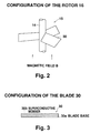
- FIG. 2 is an enlarged schematic perspective view of the rotor 16 of the embodiment of FIG. 1.
- FIG. 3 is a schematic cross-sectional lateral view of one of the screw blades 30 of the rotor 16 of the embodiment of FIG. 2.
- FIG. 4 is a schematic illustration of the forces applied to the screw 30 of FIG. 3.
- FIG. 5 is a schematic cross-sectional lateral view of a second embodiment of a superconductor motor according to the invention.
- FIG. 6 is an enlarged schematic perspective view of a third embodiment of a superconductor motor according to the invention.
- FIG. 7 is a schematic cross-sectional lateral view of a fourth embodiment of a superconductor motor according to the invention.
- FIG. 8 is an enlarged schematic perspective view of the rotor of the fourth embodiment of FIG. 7, illustrating the profile of one of the heaters 40.
- FIG. 9 is a graph illustrating the performance of the motor of the fourth embodiment of FIG. 7.
- FIG. 10 is a schematic cross-sectional lateral view of a fifth embodiment of a superconductor motor according to the invention.
- FIG. 11 is a graph illustrating the performance of the motor of the fifth embodiment of FIG. 10.
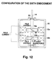
- FIG. 12 is a schematic cross-sectional lateral view of a sixth embodiment of a superconductor motor according to the invention.
- FIG. 13 is a schematic cross-sectional lateral view of a seventh embodiment of a superconductor motor according to the invention.
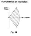
- FIG. 14 is a graph illustrating the performance of the motor of the seventh embodiment of FIG. 13.
- FIG. 1 is a schematic cross-sectional lateral view of a first embodiment of a superconductor motor according to the invention.
- the motor comprises a solenoid coil 12 for the motor field system and a rotor 16 secured to a drive shaft 14, for the transmission of rotary power, all of which are housed in a cooling container 10.
- the drive shaft 14 is rotatably supported by the bottom wall of the cooling container 10 by way of a bearing 18 and its top runs through the upper wall of the cooling container 10 and is held in position by another bearing 20.
- the cooling container 10 has a cylindrical profile and is typically made of a non-magnetic material such as FRP (reinforced plastic) or SUS304 (stainless steel). It contains therein a refrigerant such as liquid helium, liquid hydrogen or liquid nitrogen. The refrigerant is selected depending on the critical temperature of the superconductive material of the rotor. Alternatively, depending on the circumstances, a freezer may also be used to produce a desired temperature without using any refrigerant.
- the solenoid coil 12 is placed in the cooling container 10 and has, at the center thereof, a bore (space) for receiving the rotor 16.
- the solenoid coil is realized by winding a superconductive wire, typically made of NbTi (niobium titanium), and reaches a superconductive state in the refrigerant.
- a superconductive material made of an oxide of Bi or Y may be used for the solenoid coil.
- the solenoid coil 12 can be fed with a field current from an external power source so that a permanent current flows.
- the drive shaft 14 is typically made of a non-magnetic material such as FRP or SUS304 and designed to have a strength to accomodate the output torque of the motor.
- the rotor 16 has a plurality of screw blades 30 (three in the drawing) fitted to the outer periphery of the drive shaft 14.
- FIG. 3 illustrates one of the blades in cross section. It comprises a blade base 30a made of a non-magnetic material and a superconductive member 30b formed on the upper surface of the blade base 30a.
- the superconductive member 30b is formed by arranging a layer of a superconductive material such as NbTi on the blade base 30a and has a thickness sufficient to block any magnetic flux trying to pass therethrough.
- Each of the screw blades 30 has a rectangular plan view and is fitted aslant to the drive shaft 14.
- the rotor 16 operates as a screw.
- each of the screw blades 30 may be realized in any appropriate form that is commonly used for fans or propellers. If the blade base 30a and the rotary shaft 14 are made of the same material, they may be secured to each other easily. If the superconductive member 30b and the solenoid coil 12 are made of a same superconductive material, they may conveniently and effectively reach a superconductive state in the same refrigerant.
- bearings 18, 20 are made of a non-magnetic material such as a ceramic material and the bearing 20 also operates as a sealing member for the cooling container 10.
- the solenoid coil 12 is securely held in position in the cooling container 10 by means of one or more appropriate guide members made of a non-magnetic material.
- a one-directional magnetic field is produced within its bore.
- a magnetic field directed from below to above may be formed by the solenoid coil 12.
- the rotor 16 is arranged within the bore of the solenoid coil 12 and includes a number of screw blades 30 that are arranged aslant relative to the drive shaft of the motor.
- a repulsive force is generated against magnetic field B and directed perpendicularly relative to the surface of each of the screw blades 30 to consequently drive the rotor. More specifically, a diamagnetic current runs through the superconductive member 30b on each of the screw blades 30 to completely block the entry of the magnetic flux of the magnetic field B, and a repulsive force against magnetic field B is also generated in the superconductive member 30b by its diamagnetic property, it is directed perpendicularly from the surface of the superconductive member 30b.
- a reactive repulsive force is also generated so that a component of the reaction directed along the rotary direction of the rotor 16 operates as a rotary force applied to the screw blade 30.
- the rotor 16 is driven to rotate by the rotary force and transmits an output torque to the drive shaft.
- this embodiment of a superconductor motor comprises as fundamental components thereof only a solenoid coil 12 and a rotor 16 provided with superconductive members 30b in a very simplified configuration. Since only a one- directional electric current is made to flow through solenoid coil 12, the system for controlling the electric current can be made very simple.
- the superconductor motor can easily be adapted to high output power operation by increasing the number of rotors 16 and/or that of screw blades 30. Additionally, since a constant electric current can easily be made to flow in only one-direction, a large magnetic field, and thus, high output power may easily be produced by using a superconductive coil for the solenoid coil 12.
- the solenoid coil 12 can be cooled easily by the same cooling facility used for maintaining the rotor 16 in a superconductive state, a superconductive solenoid can easily be used to enhance the effectiveness of the motor.
- the rotor can also be driven to rotate in the opposite direction by inverting the flow of the electric current running through the solenoid coil 12.
- FIG. 5 is a schematic cross-sectional lateral view of a second embodiment of a superconductor motor according to the invention.
- the drive shaft 14 of this embodiment is axially slidable. More specifically, the drive shaft 14 is slidably supported by guides 22 and 24, at the bottom and at the upper portion thereof, respectively, so that it may be axially movable whenever necessary.
- each of the screw blades 30 is subjected to a reaction that is perpendicular to the surface of the blade, there is an axial force component which forces the drive shaft 14 to slide axially.
- the superconductor motor may suitably be used for a drill or some grinding apparatus.
- the rotary force and the axial force has a given fixed ratio, they can be regulated simultaneously without difficulty.
- the ratio can also be modified by changing the fitting-angle of the screw blades 30 relative to the drive shaft.
- the rotor can also be driven to rotate in the opposite direction and the drive shaft can be made to slide in the opposite direction by inverting the flow of the electric current running through the solenoid coil 12.
- FIG. 6 is an enlarged schematic perspective view of the rotor 16 of a third embodiment of a superconductor motor according to the invention.
- the rotor 16 is covered by a molded member made of a non-magnetic material such as FRP and having a disc-shaped overall profile.
- the rotor 16 comprises a disc-shaped FRP molded member 26 containing screw blades 30 therein.
- the molded member 26 is made of a non-magnetic material, the operation of the motor is not affected by the member.
- this embodiment operates exactly the same as the first embodiment.
- both the friction between the revolving rotor 16 and the refrigerant and the turbulence of the refrigerant are minimized by using such a molded member so that the rate of evaporation of the refrigerant is reduced.
- the resistance is reduced, the torque loss of the motor is lessened and the motor can be operated very efficiently.
- FIGS. 7 and 8 are schematic views for a fourth embodiment of a superconductor motor according to the invention.
- each of the screw blades 30 of the rotor 16 is provided with a patterned heater 40.
- the patterned heater 40 comprises a rectangular heater section 40a covering a portion of the front of the screw blade 30 and a wire section 40b extending between the heater section 40a and the drive shaft 14.
- the wire section 40b is electrically connected to an external power source by way of a wire 42, a slip ring 44 arranged on the drive shaft 14, and a control section 46.
- the patterned heater 40 is supplied with electric power from the external power source, the heated area of the screw blade 30 is brought to a normal (non-superconducting) conducting state. Then, the magnetic field of the solenoid coil 12 can pass through this area and the reaction force is reduced on part of the screw blade 30.
- the three screw blades 30 are provided with respective patterned heaters 40 that are identical and supplied with power from respective slip rings 44, although the three slip rings 44 may be replaced by a single slip ring 44, so that the power supply to the three patterned heaters 40 may be turned on and off by a single action.
- the patterned heaters 40 are energized, the corresponding areas of the screw blades 30 are brought into a normal conducting state.
- the overall superconductive area of the rotor 16 can be modified by supplying power to the patterned heaters 40 to regulate the motor output torque.
- the motor output torque can be regulated in three steps. It should also be understood that the motor output torque can also be modified by changing the number of and the surface area of the patterned heaters.
- FIG. 9 is a graph illustrating the performance of the motor of this fourth embodiment.
- the motor output torque can be modified for the same field current intensity.
- the motor can be operated over a wide output torque range and hence has a wide performance range.
- FIG. 10 is a schematic cross-sectional lateral view of a fifth embodiment of a superconductor motor according to the invention.
- the rotors 16a, 16b are provided with respective sets of screw blades 30 that are arranged as mirror images. More specifically, if the screw blades 30 of the rotor 16a are twisted clockwise, those of the rotor 16b are twisted counterclockwise.
- the upper rotor 16a in FIG. 10 is provided with patterned heaters (not shown) as in the case of the fourth embodiment, which are connected to an external power source by way of wires 42, slip rings 44 and a control section 46.
- the drive shaft 14 produces an output torque that reflects the difference of the rotary force between rotor 16b and rotor 16a.
- the output torque of the motor can be modified over a wide range by changing the number and the surface area of patterned heaters.
- the motor can be braked by reducing or removing the power supply to the patterned heaters to bring the output torque to nil.
- a plurality of levels can be realized for the output torque by controlling the power supply to the patterned heaters by means of the control section 46 without changing the intensity of the field current.
- the output torque of the motor is made equal to nil.
- the motor in this embodiment can be braked by suspending the power supply to the patterned heaters, it does not require the use of any separately provided brake so that the overall size of the motor can be reduced. Additionally, since the rotors 16a, 16b are identical except that they carry respective sets of screw blades to show mirror images relative to each other, they can be operated uniformly as a brake for any level of torque.
- the direction of the output torque of the drive shaft 14 can be controlled by controlling the power supply to the patterned heaters to give rise to a desired level of reverse torque. Then, the rotors can also be operated as reverse brakes.
- FIG. 12 is a schematic cross-sectional lateral view of a sixth embodiment of a superconductor motor according to the invention.
- This embodiment comprises two solenoid coils 12a, 12b.
- a pair of rotors 16a, 16b are respectively arranged in the bores of the solenoid coils.
- the solenoid coils 12a, 12b have oppositely directed windings to produce oppositely directed magnetic fields.
- the solenoid coil 12a produces a magnetic field B directed from above to below
- the solenoid coil 12b produces a magnetic field B directed from below to above.
- the rotors 16a, 16b are provided with respective sets of screw blades 30 that are directed oppositely.
- the rotors 16a, 16b produce identical rotary forces so that the drive shaft 14 shows an output torque equal to the sum of these rotary forces.
- the rotors 16a, 16b of this embodiment produce not only rotary forces but also axial forces. Since the axial force produced by the rotor 16a is directed downward and the axial force produced by the rotor 16b is directed upward, they are offset by each other to reduce the load on the bearings and hence improve their durability.
- the embodiment can produce a high output level because of the provision of two solenoid coils 12a, 12b and two rotors 16a, 16b.
- the screw blades of this embodiment may also be provided with patterned heaters to appropriately control the output torque of the motor.
- FIG. 13 is a schematic cross-sectional lateral view of a seventh embodiment of a superconductor motor according to the invention.
- This embodiment also comprises two solenoid coils 12a, 12b, to which respective field currents are supplied from respective power sources.
- the permanent currents running respectively through the solenoid coils 12a, 12b can be controlled independently so that the magnetic fields produced by the solenoid coils 12a, 12b can also be controlled independently.
- the output torque of the motor can vary over a wide range by controlling the direction and the level of the field current for the solenoid coils 12a and 12b as indicated by the shaded area in FIG. 14.
- the rotation direction and the output torque produced by solenoid coils 12a and 12b can be controlled independently by means of a relatively simple control system to make the motor operate highly efficiently.
- the screw blades in this embodiment can also be provided with patterned heaters as an additional control for the output level of the motor.
Landscapes
- Engineering & Computer Science (AREA)
- Power Engineering (AREA)
- Superconductive Dynamoelectric Machines (AREA)
Applications Claiming Priority (2)
| Application Number | Priority Date | Filing Date | Title |
|---|---|---|---|
| JP140683/95 | 1995-06-07 | ||
| JP14068395A JPH08336275A (ja) | 1995-06-07 | 1995-06-07 | 超電導モータ |
Publications (1)
| Publication Number | Publication Date |
|---|---|
| EP0748033A2 true EP0748033A2 (de) | 1996-12-11 |
Family
ID=15274333
Family Applications (1)
| Application Number | Title | Priority Date | Filing Date |
|---|---|---|---|
| EP96108576A Withdrawn EP0748033A2 (de) | 1995-06-07 | 1996-05-30 | Supraleitender Motor |
Country Status (2)
| Country | Link |
|---|---|
| EP (1) | EP0748033A2 (de) |
| JP (1) | JPH08336275A (de) |
Cited By (6)
| Publication number | Priority date | Publication date | Assignee | Title |
|---|---|---|---|---|
| WO2010131056A2 (en) | 2009-05-15 | 2010-11-18 | Nassikas A Athanassios | Magnetic propulsion method and mechanism using magnetic field trapping superconductors |
| WO2013110960A1 (en) | 2012-01-23 | 2013-08-01 | Nassikas A Athanassios | Apparatus for generating a propulsive force using superconductors |
| WO2014040145A1 (en) * | 2012-09-17 | 2014-03-20 | Guina Research And Development Pty Ltd | Electromagnetic turbine |
| EP2792056A4 (de) * | 2011-12-16 | 2016-04-06 | Heron Energy Pte Ltd | Hochgeschwindigkeitsturbine |
| WO2016142721A1 (en) | 2015-03-09 | 2016-09-15 | Nassikas A Athanassios | Mechanism creating propulsive force by means of a conical coated tape superconducting coil |
| WO2021038255A2 (en) | 2019-08-28 | 2021-03-04 | Nassikas Athanassios A | Device for generating propulsion force by using a superconductive solenoid |
Family Cites Families (1)
| Publication number | Priority date | Publication date | Assignee | Title |
|---|---|---|---|---|
| JPS514504A (ja) * | 1974-06-29 | 1976-01-14 | Kenzo Kagei | Chodendotankyokuhatsudensochi |
-
1995
- 1995-06-07 JP JP14068395A patent/JPH08336275A/ja active Pending
-
1996
- 1996-05-30 EP EP96108576A patent/EP0748033A2/de not_active Withdrawn
Cited By (9)
| Publication number | Priority date | Publication date | Assignee | Title |
|---|---|---|---|---|
| WO2010131056A2 (en) | 2009-05-15 | 2010-11-18 | Nassikas A Athanassios | Magnetic propulsion method and mechanism using magnetic field trapping superconductors |
| EP2792056A4 (de) * | 2011-12-16 | 2016-04-06 | Heron Energy Pte Ltd | Hochgeschwindigkeitsturbine |
| US9866097B2 (en) | 2011-12-16 | 2018-01-09 | Heron Energy Pte Ltd | High speed turbine |
| WO2013110960A1 (en) | 2012-01-23 | 2013-08-01 | Nassikas A Athanassios | Apparatus for generating a propulsive force using superconductors |
| WO2014040145A1 (en) * | 2012-09-17 | 2014-03-20 | Guina Research And Development Pty Ltd | Electromagnetic turbine |
| CN104798291A (zh) * | 2012-09-17 | 2015-07-22 | 吉纳能源有限公司 | 电磁涡轮发电机 |
| RU2635391C2 (ru) * | 2012-09-17 | 2017-11-13 | Херон Энерджи Пте. Лимитед | Электромагнитная турбина |
| WO2016142721A1 (en) | 2015-03-09 | 2016-09-15 | Nassikas A Athanassios | Mechanism creating propulsive force by means of a conical coated tape superconducting coil |
| WO2021038255A2 (en) | 2019-08-28 | 2021-03-04 | Nassikas Athanassios A | Device for generating propulsion force by using a superconductive solenoid |
Also Published As
| Publication number | Publication date |
|---|---|
| JPH08336275A (ja) | 1996-12-17 |
Similar Documents
| Publication | Publication Date | Title |
|---|---|---|
| US5723928A (en) | Induction motor and method of adjusting power factor of the same | |
| US5045741A (en) | Dual-motion apparatus | |
| US6005462A (en) | Electromagnetic core-energy actuator | |
| US7382072B2 (en) | Generator | |
| KR20050071703A (ko) | 자석 구조물, 상기 자석 구조물을 채용한 모터 및 상기모터를 구비하는 드라이버 | |
| WO1988002192A1 (en) | Improved brushless d.c. motor | |
| US20030057793A1 (en) | Rotor axial activation modulation of electric machinery due to reverse torque | |
| JP2002505066A (ja) | 磁気軸支電気駆動装置 | |
| JP4320409B2 (ja) | 磁気軸支電気駆動装置 | |
| WO1996022630A1 (en) | Improvements relating to magnetic coupling systems | |
| US20040150289A1 (en) | Universal motor/generator/alternator apparatus | |
| US5723925A (en) | Superconductor motor provided with superconductor shield | |
| WO1985005741A1 (fr) | Moteur pas a pas | |
| US20030048021A1 (en) | Disk type D.C. motor having a non-ferrous stator | |
| JPH08336275A (ja) | 超電導モータ | |
| US20040080229A1 (en) | Controlled reluctance AC induction motor | |
| GB2275371A (en) | An electronically commutated electric motor | |
| JPH03117359A (ja) | 軸方向ギャップ超伝導電気機械 | |
| McGuinness | Advantages of five phase motors in microstepping drive | |
| EP3714528B1 (de) | Vorrichtung und verfahren zur modularen stabilisierung von nabenlosen rotoren | |
| JPS62268390A (ja) | 可変速誘導電動機 | |
| US20050194856A1 (en) | Controlled reluctance AC induction motor | |
| CN100424985C (zh) | 同步电动机的控制装置及其控制方法 | |
| JP3628156B2 (ja) | 回転軸の位置制御方法 | |
| US20230163663A1 (en) | Energy-saving brushless motor-kinetic generator with energy-saving function |
Legal Events
| Date | Code | Title | Description |
|---|---|---|---|
| PUAI | Public reference made under article 153(3) epc to a published international application that has entered the european phase |
Free format text: ORIGINAL CODE: 0009012 |
|
| 17P | Request for examination filed |
Effective date: 19960703 |
|
| AK | Designated contracting states |
Kind code of ref document: A2 Designated state(s): DE FR GB |
|
| RHK1 | Main classification (correction) |
Ipc: H02K 55/00 |
|
| STAA | Information on the status of an ep patent application or granted ep patent |
Free format text: STATUS: THE APPLICATION IS DEEMED TO BE WITHDRAWN |
|
| 18D | Application deemed to be withdrawn |
Effective date: 19981201 |