EP0747715A2 - Mehrphasenmessung - Google Patents
Mehrphasenmessung Download PDFInfo
- Publication number
- EP0747715A2 EP0747715A2 EP96304216A EP96304216A EP0747715A2 EP 0747715 A2 EP0747715 A2 EP 0747715A2 EP 96304216 A EP96304216 A EP 96304216A EP 96304216 A EP96304216 A EP 96304216A EP 0747715 A2 EP0747715 A2 EP 0747715A2
- Authority
- EP
- European Patent Office
- Prior art keywords
- current
- vector sum
- bushing
- signal
- accordance
- Prior art date
- Legal status (The legal status is an assumption and is not a legal conclusion. Google has not performed a legal analysis and makes no representation as to the accuracy of the status listed.)
- Withdrawn
Links
Images







Classifications
-
- G—PHYSICS
- G01—MEASURING; TESTING
- G01R—MEASURING ELECTRIC VARIABLES; MEASURING MAGNETIC VARIABLES
- G01R27/00—Arrangements for measuring resistance, reactance, impedance, or electric characteristics derived therefrom
- G01R27/02—Measuring real or complex resistance, reactance, impedance, or other two-pole characteristics derived therefrom, e.g. time constant
- G01R27/26—Measuring inductance or capacitance; Measuring quality factor, e.g. by using the resonance method; Measuring loss factor; Measuring dielectric constants ; Measuring impedance or related variables
- G01R27/2688—Measuring quality factor or dielectric loss, e.g. loss angle, or power factor
-
- G—PHYSICS
- G01—MEASURING; TESTING
- G01R—MEASURING ELECTRIC VARIABLES; MEASURING MAGNETIC VARIABLES
- G01R15/00—Details of measuring arrangements of the types provided for in groups G01R17/00 - G01R29/00, G01R33/00 - G01R33/26 or G01R35/00
- G01R15/04—Voltage dividers
- G01R15/06—Voltage dividers having reactive components, e.g. capacitive transformer
-
- G—PHYSICS
- G01—MEASURING; TESTING
- G01R—MEASURING ELECTRIC VARIABLES; MEASURING MAGNETIC VARIABLES
- G01R15/00—Details of measuring arrangements of the types provided for in groups G01R17/00 - G01R29/00, G01R33/00 - G01R33/26 or G01R35/00
- G01R15/14—Adaptations providing voltage or current isolation, e.g. for high-voltage or high-current networks
- G01R15/142—Arrangements for simultaneous measurements of several parameters employing techniques covered by groups G01R15/14 - G01R15/26
-
- G—PHYSICS
- G01—MEASURING; TESTING
- G01R—MEASURING ELECTRIC VARIABLES; MEASURING MAGNETIC VARIABLES
- G01R31/00—Arrangements for testing electric properties; Arrangements for locating electric faults; Arrangements for electrical testing characterised by what is being tested not provided for elsewhere
- G01R31/12—Testing dielectric strength or breakdown voltage ; Testing or monitoring effectiveness or level of insulation, e.g. of a cable or of an apparatus, for example using partial discharge measurements; Electrostatic testing
- G01R31/1227—Testing dielectric strength or breakdown voltage ; Testing or monitoring effectiveness or level of insulation, e.g. of a cable or of an apparatus, for example using partial discharge measurements; Electrostatic testing of components, parts or materials
-
- H—ELECTRICITY
- H02—GENERATION; CONVERSION OR DISTRIBUTION OF ELECTRIC POWER
- H02H—EMERGENCY PROTECTIVE CIRCUIT ARRANGEMENTS
- H02H1/00—Details of emergency protective circuit arrangements
- H02H1/0007—Details of emergency protective circuit arrangements concerning the detecting means
- H02H1/0015—Using arc detectors
Definitions
- the present invention relates to a multi-phase measuring system to be used for the determination of certain electrical characteristics of electrical power apparatus.
- the present description pertains to a method for the evaluation of the quality of high voltage insulation systems.
- the procedure covers an application for the measurement of changes in capacitance and/or power factor of either transformer bushings or other electrical apparatus in which the line-to-ground insulation may be considered to be part of a capacitance system.
- the measurements are made while the apparatus is energized during normal service operation.
- a method of monitoring a group of three bushings in a three-phase alternating current network connected in parallel to a three-phase voltage supply includes producing a current output from a tap of each bushing and adding the current outputs from the bushing taps vectorially to obtain a vector sum bushing current.
- Apparatus according to the invention includes three reference devices connected in parallel to the three-phase voltage supply to produce a current output from each reference device, and a vector adder that vectorially adds the current outputs from the reference devices to obtain a vector sum reference current. Differentially combining the vector sum reference current with the vector sum bushing current provides a difference current representative of a bushing condition.
- the reference devices may be other groups of bushings, or potential transformers, or coupling capacitor voltage transformers (CCVTs), or bushing potential devices, or high voltage current transformers, or optical voltage transducers. If potential transformers or other voltage devices are used as references, they may be loaded with resistors so that the currents through the resistors are substantially equal to the currents derived from the taps of the bushings. Further, the vector sum bushing current may be delayed by ninety degrees before differentially combining the vector sum potential transformer current to correct for a phase difference between the two vector sum currents.
- CCVTs coupling capacitor voltage transformers
- successive vector difference currents may be differentially combined to provide a sequence of incremental vector difference currents. That is to say, the group of bushings and reference devices may be periodically scanned. The vector sum bushing currents may be converted into a signal suitable for transmission for remote monitoring. The current outputs of each bushing may be scaled, by electronic gain or through taps in the primary windings of a current transformer. The current outputs from the bushings and the reference devices may, if necessary, be corrected for temperature effects.
- Apparatus may include a detector for obtaining the bushing current outputs and a means for combining the bushing current outputs into a vector sum bushing current (resultant) and comparing the vector sum bushing current with a vector sum reference current.
- the detector may be a portable device.
- a multiplexer may be used to simultaneously scan pairs of bushing groups and reference voltage devices connected in parallel on the same bus.
- the multiplexer and detector may be located at a remote station. The current outputs and the reference current may be transmitted to the remote station in digital form.
- a method of diagnosing the conditions of a group of bushings on a multi-phase alternating current network may include calculating a differential value indicative of a change of capacitance and/or power factor of the bushings, and providing a message to the user if the differential value exceeds a threshold value.
- the difference between the differential value and the threshold may be determined to be large or small, which may be indicated in the message to the user.
- the threshold value may be determined from prior stored measurements taken from the bushings.
- the initial values of the capacitance and power factor of the bushings may be stored.
- the approximate values of the capacitance and power factors of the bushings may be estimated based on detected changes and the stored initial values of the capacitance and power factor.
- An advantage of the present invention is to permit monitoring of bushings in which the capacitance and/or power factor of the bushings change.
- Another advantage is to provide an economical monitoring system since only one signal from each group of bushings is monitored and analyzed.
- the method and apparatus of the invention may be used to monitor the degradation of high voltage bushing insulation systems during normal operation.
- the bushings of high voltage power transformers account for a high percentage of transformer problems. When a transformer bushing fails, it may result in the destruction of the entire transformer and other damage.
- the invention may also be used to monitor the degradation of high voltage current transformer insulation systems. Such transformers are frequently provided with taps in the high voltage insulation structure and, on three-phase networks, the current transformers can be monitored by comparing a set of three transformers against another reference set on the same parallel voltage bus. Alternatively, the first set of current transformers may be compared against a set of transformer bushings or against a set of reference voltage devices.
- Periodic diagnostic measurements made on transformer bushings provide evidence of a trend in the measured quantities which would be indicative of deteriorating insulation.
- the apparatus and method of the present invention allows for on-line monitoring of transformer bushings.
- Typical quantities measured during diagnostic tests of bushings are the values of capacitance and power factor relating to the capacitances C 1 between the high voltage source 8 and the potential taps 20, 21 and 22 and the tap capacitances C 2 between the potential taps 20, 21 and 22 and the bushing mounting flanges connected to ground.
- An increase or decrease in capacitance and/or power factor between diagnostic measurements is considered to be due to insulation deterioration.
- the bushing monitoring system is especially advantageous for monitoring apparatus installed in 3-phase alternating current networks.
- the present invention utilizes the property that even though all three bushings on a given 3-phase transformer will age at the same rate initially, as the insulation degradation progresses, one bushing will eventually begin to deteriorate at a faster rate than the other two.
- Bushing capacitance and power factor values increase with age, and the invention detects when either of these quantities has increased on any bushing by a predetermined amount above the corresponding values of the other two bushings in a 3-phase group.
- the three bushings may not be identical with respect to capacitance and power factor, even if they are made by the same manufacturer and are of the same type. Minor variations in capacitance and power factor are normal and will cause a resultant vector sum bushing current I o to flow into the detector 30.
- the system voltage may not always be perfectly balanced. Variations in line-to-ground voltages may occur and cause corresponding variations in the bushing currents I A , I B and I C . Such variations may produce detectable variations in the vector sum bushing current I o .
- the change in the vector sum bushing current I o may be greater than the maximum acceptable levels caused by changes in bushing characteristics due to aging. Variations in system balance are compensated for to avoid false determinations of deterioration.
- the compensation procedure involves subtracting from the vector sum of the bushing currents I A , I B and I C the vector sum of a reference group of currents derived from the same voltage bus.
- the procedure utilizes signals proportional to the line-to-ground voltage of the transmission system.
- the signals are derived from high voltage potential transformers which are installed in the same substation as the power transformer and which are electrically in parallel with the bushings to be monitored.
- the reference currents are derived from another group of three bushings all on the same parallel voltage bus.
- the number of bushings to be monitored may be any multiple of three, provided each of these bushings is on the same parallel voltage bus.
- the reference currents may also be obtained from coupling capacitor voltage transformers, bushing potential devices or optical voltage transducers.
- the system may also be used for circuit breaker bushings and high voltage current transformers.
- FIG. 2 illustrates the compensation procedure.
- Three identical potential transformers 40, 41 and 42 are electrically in parallel with the bushings 10, 11 and 12 to be monitored.
- the secondary windings of potential transformers 40, 41 and 42 are loaded with identical resistors R, the values of which are selected so that the current outputs i A , i B and i C are approximately equal to the bushing currents I A , I B and I C .
- the ratios of the potential transformer currents to the bushing currents are approximately unity, and the vector sum potential transformer current i o is proportional to the degree of unbalance of the system voltages.
- the vector sum bushing current I o also reflects changes in system imbalance. Therefore, differentially combining the vector sum transformer current i o with the vector sum bushing current I o furnishes a difference current i D representing only those differences caused by changes in capacitance and/or power factor of one of the bushings.
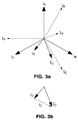
- FIG. 3 pertains to a comparison between the resultant current from a bushing set and a resultant reference current derived from a set of potential transformers.
- the residual vector current from the bushing set must be delayed by 90° before being differentially combined with the residual reference current.
- the residual reference current is derived from some other set of voltage devices such as coupling capacitor voltage transformers (CCVTs), bushing potential devices, and optical voltage transducers.
- CCVTs coupling capacitor voltage transformers
- the residual reference current is derived from another set of bushings or a set of high voltage current transformers, for example, the 90° delay in the residual vector current from the bushing set being monitored is not required.
- the bushing currents I A , I B and I C together with their residual vector sum bushing current I o are shown by the dashed lines.
- the potential transformer reference currents i A , i B and i C together with their resultant vector sum i o are shown by the solid lines in FIG. 3a.
- the resultant currents I o and i o are not to scale but have been exaggerated for the purpose of explanation.
- the bushing currents I A , I B and I C lead the transformer currents by approximately 90°. Therefore, I o must be delayed by 90° to position I' o before differentially combining it with the vector sum transformer current i o .
- the differential combination of I' o and i o yields a vector difference current i D as shown in FIG. 3b.
- the vector sum bushing current I o results from the combination of unequal capacitances C 1 and unbalanced line-to-ground voltages.
- the vector sum transformer current i o also is the result of unbalanced system voltages.
- the difference current i D is obtained by differentially combining the vector sum potential transformer current i o with the vector sum bushing current I' o .
- the detection system detects the currents I o and i o and the phase angle between them. It phase shifts the current I o by 90° to I' o and then computes the difference current i D .
- the difference current i D is independent of the degree of system balance. If a change occurs in either the capacitance C 1 or the power factor or both of any of the three bushings, a change in the difference current i D will be detected and, if it exceeds a predetermined level, detector 30 furnishes an alarm to the user.
- FIG. 4 illustrates how a change in system balance affects the resultant currents from two sets of bushings.
- the initial currents from the bushings being monitored are I A , I B , and I C and their resultant current is I o .
- the currents from the reference set of bushings are i A , i B and i C .
- the resultant current from the reference set of bushings is i o .
- I A equals i A .
- Currents i B and i C are approximately equal to I B and I C . If necessary, scaling may be performed in order to match as closely as possible the currents from the two sets of bushings.
- the vector difference between the two sets of resultant currents is i D .
- the vector difference i D changes to i' D .
- the vector difference does not change in magnitude or phase angle relative to its original value. Therefore, the vector difference is insensitive to a variation in system balance as described. If, however, a change occurs in either the capacitance or the power factor of a bushing of either set, the resultant of only that set will change, thereby causing a change in the vector difference relative to its original value.
- the currents from one set of bushings may not be exactly equal to those from the other set, even after scaling. Consequently, the vector differences i D and i' D may not be identical following a change in system balance. Nevertheless, the difference between the two difference vectors will be very small and is typically less than the minimum alarm threshold level, irrespective of the type of system imbalance.
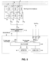
- the schematic diagram of FIG. 5 shows another embodiment, a method of monitoring multiple groups of bushings on different voltage buses.
- a signal conversion device 50 located in the vicinity of each transformer converts the vector sum bushing current I o into a signal suitable for transmission, preferably in digital form, to the substation control room or computer 51 to be processed. Signals from all the substation potential transformers are available at substation control room 51 through respective resistors R. The current signals may be scanned before processing.
- Multiplexer 65 cyclically scans pairs of bushing group signals and their corresponding potential transformers on the same bus, so that all the bushings in a substation can be monitored by multiplexer 65.
- the scanning and detector circuitry may be controlled by computer 60, which also processes the detected data and provides an alarm signal when the difference signal exceeds the predetermined threshold level.
- CCVTs coupling capacitor voltage transformers
- potential transformers for the measurement of transmission voltages, particularly at higher voltage levels.
- CCVTs would replace the potential transformers in FIG. 2. Since the ratios of CCVTs can change slowly with time due to the aging of their capacitors, the system will also detect a change in balance caused by a CCVT ratio change.
- the potential transformers in FIG. 2 may be replaced by a second group of three bushings connected in parallel to the same bus as the three bushings to be monitored. In this case the 90° rotation of the residual current vector is not required.
- the problem bushing could be in either transformer, and further signal processing will enable the defective unit to be identified.
- FIG. 6 shows a simplified method of performing occasional on-line checks on bushings at the location of the transformer. Measurements may be taken by the M4000 Insulation Analyzer 70 commercially available from Doble Engineering Company. The initial balance conditions are recorded and utilized as reference conditions during future checks. Using this arrangement, the M4000 Insulation Analyzer 70 is only connected to the local bushing monitor terminals when bushing conditions are checked.
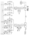
- FIG. 10 An arrangement for monitoring two or more sets of bushings is shown in FIG. 10.
- the currents from each set of bushings is fed into a Junction Box, "JB”, which is normally mounted on the side of each transformer.
- JB Junction Box
- CT Current Transformer
- DAU Data Acquisition Unit
- OPD Overvoltage Protection Devices
- LAN Local Area Network
- the residual currents are digitized in the DAU and then transmitted to the substation computer for further processing.
- the processing involves the computation of residual vector differences between pairs of bushing sets.
- the vector differences are compared with initial values and, if a threshold level is exceeded, an alarm is provided for the user. Alarms of different levels of priority are provided depending on the magnitude of the change in the difference vector. Temperature corrections are also made and the suspect bushing is identified.
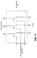
- the Junction Box JB contains switches S 1 , S 2 , S 3 which enable the bushing currents to be directed to another set of off-line measuring terminals as shown in FIG. 11. These terminals may be used for on-line or off-line measurements on the bushings one phase at a time. Also included in the Junction Box but not shown in the diagram is a set of auxiliary contacts which provide a signal to the DAU indicating the position of the switch within the Junction Box.
- CT 1 , CT 2 may be used for the scaling CT. These are shown in FIG. 12.
- CT 1 has three separate primary windings W 1 , W 2 , W 3 as shown, and each primary has a number of taps.
- CT 2 has only one primary winding W 4 with taps.
- auxiliary current transformer "T" in series with the lead coming from the phase B bushing. The output from this auxiliary current transformer provides the reference signal which is used to identify the suspect bushing when the threshold level is exceeded.
- the power factor may increase or decrease with changes in temperature. Provided all three bushings are of the same type, the variation due to temperature will not cause a problem because temperature-related power factor changes will be identical on all three bushings. However, if the three bushings are not identical, it may be necessary to apply a correction to the vector sum bushing currents I o and i o before proceeding with the evaluation of the difference current i D . Temperature correction factors may be applied automatically by a computer 60. If the measured difference current i D exceeds the level which could be due to temperature effects, the cause may be attributed to a defective bushing.
- FIG. 7 shows part of a system used to monitor transformer bushings.
- the two vector sum current signals I o and i o are fed into two low impedance inputs 80 and 81 as shown.
- the vector sum reference current i o is derived from a set of potential transformers.
- Processing of the current signals includes amplitude adjustment in attenuators 82 and 83, A/D conversion 84, and filtering and vector resolution 85.
- Computation circuitry 90 involves delaying the vector sum bushing current I o by 90° and differentially combining the signal corresponding to the vector sum potential transformer current i o with the signal corresponding to the vector sum bushing current I o delayed by 90°.
- the difference signal output i D may then be fed to computer 60.
- the inputs of the algorithm include the imbalance currents associated with the bushings to be monitored and external ambient and transformer top oil temperatures required to estimate the temperature of the insulation in the bushings.
- Each of the imbalance currents represents the vector sum of the insulation currents of the three bushings, one on each phase of the voltage apparatus.
- the outputs of the algorithm are the temperature-compensated values of the capacitance and power factor of each of the bushings.
- the algorithm is executed every time a measurement of the bushing imbalance currents is made.
- the first step in the algorithm is to compute the residual of the imbalance currents for every set of bushings.
- the form of the residual R i is chosen to emphasize deviations from the initial imbalance current. This eliminates non-uniform variation in the magnitude of the residual that are associated with the initial imbalance current vector.
- the difference in the imbalance currents is normalized to the sum of the initial capacitances to reduce the effects of system imbalance when the capacitances of the bushings in the sets are significantly different.
- the next step in the algorithm involves the computation of the magnitude of the differences between residuals of every possible permutation of bushing sets taken two at a time.
- the total number of permutations P is For example, for two sets of bushings, there is one such permutation.
- each bin count represents the number of times that a change has been detected for that bushing set over the number of permutations P.
- the first two sets change, there is more than one possible count combination (e.g., ⁇ 2, 1, 0 ⁇ , ⁇ 1, 2, 0 ⁇ or ⁇ 1, 1, 0 ⁇ ), depending on the actual magnitude of D 12 , which is affected by the relative change in the signal from set 1 compared to that from set 2.
- a maximum of M - 1 changes can be detected in any one measurement.
- one of the several possible counts for the three bins is ⁇ 0, 0, 0 ⁇ , which would lead to an incorrect conclusion that no change occurred in any of the bushings.
- the algorithm involves the comparison of each differential to a threshold value. Since the threshold represents the precision of the measurement, it should be large enough that normal variations in the imbalance currents due to temperature fluctuations in the system are not interpreted as changes in the electrical characteristics of the bushings. To ensure this, the threshold is determined by a set of statistical processes applied to the first N values of each calculated differential. The number N should be large enough to yield a statistically significant sample size. When these values have been collected, the data is used to calculate a mean and standard deviation for each permutation of differentials. The threshold is set to three times the largest standard deviation.
- the algorithm also monitors the bushings even during the initial period. This is accomplished by calculating the threshold from the user-supplied initial data and built-in values for variations in this data that reflect significant changes in the characteristics of the bushings. For example, variations of 10% in the capacitance and 1% in the power factor might be used to indicate a significant change. This initial threshold will be higher than that calculated statistically from the measured values of the imbalance currents.
- the algorithm determines in which of the two sets the change has occurred by comparing the magnitudes of the two residuals. If the magnitude of R i is greater than the magnitude of R j , the change will have occurred in the i th bushing set. Otherwise, the change will have occurred in the j th set. The change may have occurred in both bushing sets, in which case the algorithm selects the bushing set which experienced the larger change. Regardless of the outcome of the comparison, the algorithm accounts for such variations in the bin counts.
- the algorithm first determines whether the value of the threshold used in the comparison was too low by counting the number of sets with zero bin counts (M 0 ). If none of the sets have zero bin counts, then the threshold was too low and the threshold is increased by 10%. The new value of the threshold is then compared to a maximum value, such as the one used during the learning period, and if it exceeds the maximum value, a message is issued to the user to warn that a runaway condition has been detected.
- the algorithm passes through every bin and verifies that a change has occurred by ensuring that the bin count falls between the theoretical minimum (M 0 ) and maximum (M - 1) values. If this condition is met, the procedure determines which of the bushings in the set experienced the change and calculates the approximate capacitance and power factor of the affected bushing. Although only the phase angle of the residual is used to determine which bushing experienced the change, both the magnitude and phase of the residual are used to calculate the new capacitance and power factor of the bushing.
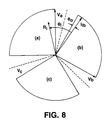
- the affected bushing is selected by examining the sector of the phase plane in which the residual vector R i lies. If the change in the capacitance and power factor of the bushing is positive, the locus of points describing the residual vector is a 90° sector bounded by the line-to-ground voltage phasor and the capacitive component of the insulation current phasor, as shown in FIG. 8 by the three shaded regions. There are also three 30° sectors which are not associated with any of these changes. These sectors are used to pad the 90° sectors so that any error in the measurement of the phase angle will not affect the diagnosis of the affected bushing. Again, the phase angle is measured with respect to the phasor I 1b .
- the change in the capacitance and power factor values are determined from the magnitude and phase of the residual.
- the capacitance is determined from the component of the residual which projects on the axis normal to the voltage phasor.
- the power factor is determined from the component of the residual that projects on to the axis parallel to the voltage phasor.
- phase angle of the residual is such that 17 12 ⁇ ⁇ ⁇ i - ⁇ 0 ⁇ 1 12 ⁇ then the change is associated with the phase b bushing.
- angle ⁇ p is equal to zero and the values of the capacitance and the power factor of the bushings are determined according to the following expressions:
- the change is associated with the phase c bushing.
- the angle ⁇ p is equal to 4 ⁇ /3 and the values of the capacitance and power factor of the bushings are determined according to the following expressions:
- the temperature-compensated values of the capacitance and power factor can be calculated for each bushing every time a recording is made.
- Signals S 1 , S 2 and S 3 are the imbalance current waveforms measured from three sets of three bushings.
- the imbalance current waveforms are filtered by filters 102, 104 and 106 and processed in the feature extractions 108, 110 and 112, which extract the imbalance current vectors (i.e. the magnitude and phase) from the waveforms.
- the imbalance current vector information is passed through low pass filters 114, 116 and 118 before the algorithm 120 compares the imbalance currents with each other and the initial values to determine whether the threshold is exceeded.
- the threshold which is unique for a given group of bushings, is determined using a learning process 130, 132 and 134.
- the learning process determines the threshold value by means of statistical processes applied to the magnitude of the imbalance current.
- the threshold is determined during an initial period when the magnitude of the imbalance current is sampled for a period of time sufficiently long to provide a large population sample.
- the initial threshold is based on the nameplate data and specifications based on off-line testing experience.
- the algorithm determines which of the bushings in the sets have changed, calculates the change in the capacitance and power factor for those bushings, temperature-compensates the calculated changes on the basis of the top-oil and ambient temperatures, and passes this information to the expert system 122.
- the expert system 122 updates the previous power factor and capacitance values, calculates the rate of change of the power factor and capacitance, and sends this information to the database 124. From the database 124, the information is available to the user 126. The expert system evaluates the results, determines whether a message should be sent to the user, and if so, what type of message.
- the threshold is not triggered.
- the algorithm indicates to the expert system that there is no change in power factor or capacitance, and there is no message to the user.
- the algorithm determines that the threshold is exceeded, calculates the change in capacitance and power factor, and passes this information to the expert system.
- the expert system updates the previous power factor and capacitance values stored in the database, and evaluates the result. If the degree of change is small (e.g., the power factor increases from 0.5% to 0.75% and there is no change in capacitance), the expert system will determine that the degree of concern is low and that there is no need to notify the user.
- the change is greater (e.g., the power factor increases from 0.75% to 1.00% and there is a change in capacitance of 1%), but not enough to require immediate attention, the user will be given a low-priority alarm message. Finally, if the change continues to increase (e.g., the power factor increases to 1.10%), the expert system issues a high-priority alarm to the user which requires immediate attention.
- the statistical process in the algorithm for the bushing monitor provides for bushings having different temperature coefficients.
- the temperature of the insulation affects the power factor of the bushings.
- the temperature of the bushing insulation is approximated by the average between the top-oil temperature in the transformer and the ambient external temperature. Temperature fluctuations in the apparatus or in the environment can lead to fluctuation in the imbalance current. These fluctuations will be larger for those bushing sets in which the bushings have different temperature coefficients. Part of the fluctuation will be removed by the low-pass filter. The remainder of the fluctuation will affect the sensitivity of the monitoring system. In particular, increased fluctuations in the imbalance current of a set of bushings will result in a larger standard deviation for the distributions of differentials associated with that set, in turn resulting in a larger threshold.
- correction for temperature variations is performed when the threshold is exceeded.
- the imbalance current changes with temperature, but this change has a frequency (12-24 hours) which is greater than the frequency of the change created by a problem in the bushings (weeks or months).
- the higher frequency component related to daily temperature variations can be filtered out.
- the threshold is exceeded, the power factor change is corrected for temperature by using top oil and ambient temperature sensors, before it is added to the previous or initial value. Different bushings have different temperature correction factors.
- the set on one side of the circuit breaker will not be subjected to the same voltage changes as the other side if the circuit breaker is open.
- the sets on the circuit breaker can still be monitored.
- the algorithm recognizes that the changes are due to an inability to account for voltage fluctuations while the circuit breaker is open. All actions with respect to bushing conditions are deferred until the measurement with the circuit breaker closed is performed.
Landscapes
- Physics & Mathematics (AREA)
- General Physics & Mathematics (AREA)
- Engineering & Computer Science (AREA)
- Power Engineering (AREA)
- Measurement Of Current Or Voltage (AREA)
Applications Claiming Priority (2)
| Application Number | Priority Date | Filing Date | Title |
|---|---|---|---|
| US08/475,407 US6177803B1 (en) | 1995-06-07 | 1995-06-07 | Monitoring elements in a multi-phase alternating current network |
| US475407 | 1995-06-07 |
Publications (2)
| Publication Number | Publication Date |
|---|---|
| EP0747715A2 true EP0747715A2 (de) | 1996-12-11 |
| EP0747715A3 EP0747715A3 (de) | 1997-07-02 |
Family
ID=23887440
Family Applications (1)
| Application Number | Title | Priority Date | Filing Date |
|---|---|---|---|
| EP96304216A Withdrawn EP0747715A3 (de) | 1995-06-07 | 1996-06-06 | Mehrphasenmessung |
Country Status (2)
| Country | Link |
|---|---|
| US (1) | US6177803B1 (de) |
| EP (1) | EP0747715A3 (de) |
Cited By (11)
| Publication number | Priority date | Publication date | Assignee | Title |
|---|---|---|---|---|
| WO2008113142A3 (en) * | 2007-03-20 | 2008-12-11 | Eduardo Pedrosa Santos | Real-time monitoring system for capacitance graded bushings |
| EP2194389A1 (de) | 2008-12-05 | 2010-06-09 | ABB Technology Ltd | Buchsendiagnose |
| CN102262203A (zh) * | 2011-04-25 | 2011-11-30 | 南京智达电气有限公司 | 一种在线监测电容套管绝缘状态的装置及其方法 |
| ITMI20121191A1 (it) * | 2012-07-06 | 2014-01-07 | Gen Electric | Sistemi, procedimenti, e dispositivi per la stima della capacita' di condensatori di potenza |
| EP3206041A1 (de) * | 2016-08-16 | 2017-08-16 | ABB Schweiz AG | System und verfahren zur überwachung von transformatordurchführungen |
| US9927466B2 (en) | 2012-07-06 | 2018-03-27 | General Electric Company | System and method for controlling dynamic output impedance of an inverter |
| EP3370073A1 (de) * | 2017-03-01 | 2018-09-05 | ABB Schweiz AG | Verfahren und vorrichtung zur bestimmung der parameter kapazitiver komponenten |
| WO2018158138A1 (de) * | 2017-02-28 | 2018-09-07 | Maschinenfabrik Reinhausen Gmbh | Verfahren und vorrichtung zur überwachung von kondensatordurchführungen für ein wechselstromnetz |
| WO2018158135A1 (de) * | 2017-02-28 | 2018-09-07 | Maschinenfabrik Reinhausen Gmbh | Verfahren und vorrichtung zur verlustfaktorüberwachung von kondensatordurchführungen |
| CN109239550A (zh) * | 2018-09-04 | 2019-01-18 | 国网山东省电力公司青岛供电公司 | 一种线路绝缘状况判断方法 |
| CN114142432A (zh) * | 2021-03-10 | 2022-03-04 | 保定钰鑫电气科技有限公司 | 一种三相供电系统的保护方法 |
Families Citing this family (16)
| Publication number | Priority date | Publication date | Assignee | Title |
|---|---|---|---|---|
| DE19916686A1 (de) * | 1999-04-14 | 2000-10-19 | Moeller Gmbh | Eingangsschaltung für relativ hochstromige zu überwachende AC-Signale |
| US6538420B2 (en) * | 2001-04-10 | 2003-03-25 | Associated Research, Inc. | Automated run test system having built-in high voltage switching matrix for interconnection to a safety compliance testing instrument |
| US6927562B2 (en) * | 2002-02-27 | 2005-08-09 | On-Line Monitoring, Inc. | Power factor/tan δtesting of high voltage bushings on power transformers, current transformers, and circuit breakers |
| CA2536083C (en) * | 2003-08-21 | 2011-06-21 | Hubbell Incorporated | Method and apparatus for measuring impedance of electrical component under high interference conditions |
| JP2005302794A (ja) * | 2004-04-07 | 2005-10-27 | Hitachi Industrial Equipment Systems Co Ltd | 変圧器監視システム |
| JP4675813B2 (ja) * | 2006-03-31 | 2011-04-27 | Okiセミコンダクタ株式会社 | 半導体記憶装置およびその製造方法 |
| WO2008148727A1 (en) * | 2007-06-07 | 2008-12-11 | Abb Technology Ag | Voltage measurements of electrically conducting elements in systems for controlling electrical processes |
| US8547112B2 (en) * | 2010-03-29 | 2013-10-01 | Eduardo Pedrosa Santos | Introduced in monitoring system of dielectric state of high voltage equipments with capacitive insulation, such as condensive bushings, current transformers, potential transformers and similar |
| US9482699B2 (en) * | 2013-06-18 | 2016-11-01 | Advanced Power Technologies, Llc | Method and apparatus for monitoring high voltage bushings safely |
| EP3650872B1 (de) * | 2018-11-08 | 2021-06-09 | ABB Power Grids Switzerland AG | Relative buchsenparameterverfahren zur vermeidung von temperatureinfluss in der absoluten buchsenparameterüberwachung in einem transformator |
| EP3715881B1 (de) * | 2019-03-28 | 2023-05-17 | Siemens Energy Global GmbH & Co. KG | Verfahren zur instandhaltung einer hochspannungsdurchführung |
| CA3158452C (en) * | 2019-11-13 | 2023-05-16 | Mitchell Lee CRANE | Systems and methods for balancing unbalanced power cables |
| CN111209640B (zh) * | 2020-02-24 | 2025-06-20 | 北京中凯晟天科技发展有限公司 | 配电网拓扑自动排序传感器终端、后台终端、系统及方法 |
| CA3236145A1 (en) | 2021-10-22 | 2023-04-27 | Southwest Electric Co. | Three-phase multi-tap balancing distribution transformer |
| CN115542018B (zh) * | 2022-10-09 | 2025-10-10 | 国网四川省电力公司电力科学研究院 | 高压套管介损和电容的在线监测方法及装置 |
| CN120275700A (zh) * | 2024-01-05 | 2025-07-08 | 台达电子企业管理(上海)有限公司 | 绝缘检测电路与绝缘检测方法 |
Family Cites Families (4)
| Publication number | Priority date | Publication date | Assignee | Title |
|---|---|---|---|---|
| US1945263A (en) * | 1931-06-24 | 1934-01-30 | Doble Eng | Apparatus for testing insulating values |
| US2146069A (en) * | 1937-07-10 | 1939-02-07 | Ohio Brass Co | Method and apparatus for testing insulation |
| US3710242A (en) * | 1971-02-12 | 1973-01-09 | Doble Eng Co | Service bushing test |
| US4757263A (en) * | 1987-05-01 | 1988-07-12 | Tennessee Valley Authority | Insulation power factor alarm monitor |
-
1995
- 1995-06-07 US US08/475,407 patent/US6177803B1/en not_active Expired - Fee Related
-
1996
- 1996-06-06 EP EP96304216A patent/EP0747715A3/de not_active Withdrawn
Cited By (27)
| Publication number | Priority date | Publication date | Assignee | Title |
|---|---|---|---|---|
| WO2008113142A3 (en) * | 2007-03-20 | 2008-12-11 | Eduardo Pedrosa Santos | Real-time monitoring system for capacitance graded bushings |
| US9128477B2 (en) | 2008-12-05 | 2015-09-08 | Abb Technology Ltd. | Bushing diagnosis |
| EP2194389A1 (de) | 2008-12-05 | 2010-06-09 | ABB Technology Ltd | Buchsendiagnose |
| CN102239416B (zh) * | 2008-12-05 | 2015-02-25 | Abb技术有限公司 | 套管诊断 |
| CN102262203A (zh) * | 2011-04-25 | 2011-11-30 | 南京智达电气有限公司 | 一种在线监测电容套管绝缘状态的装置及其方法 |
| CN102262203B (zh) * | 2011-04-25 | 2013-09-04 | 南京智达电气有限公司 | 一种在线监测电容套管绝缘状态的装置及其方法 |
| ITMI20121191A1 (it) * | 2012-07-06 | 2014-01-07 | Gen Electric | Sistemi, procedimenti, e dispositivi per la stima della capacita' di condensatori di potenza |
| US9588182B2 (en) | 2012-07-06 | 2017-03-07 | General Electric Company | Systems, methods, and devices for capacitance estimation of power capacitors |
| US9927466B2 (en) | 2012-07-06 | 2018-03-27 | General Electric Company | System and method for controlling dynamic output impedance of an inverter |
| EP3206041A1 (de) * | 2016-08-16 | 2017-08-16 | ABB Schweiz AG | System und verfahren zur überwachung von transformatordurchführungen |
| CN110325867B (zh) * | 2017-02-28 | 2022-07-05 | 赖茵豪森机械制造公司 | 用于监控用于交流电网的电容型套管的方法和设备 |
| WO2018158138A1 (de) * | 2017-02-28 | 2018-09-07 | Maschinenfabrik Reinhausen Gmbh | Verfahren und vorrichtung zur überwachung von kondensatordurchführungen für ein wechselstromnetz |
| CN110325867A (zh) * | 2017-02-28 | 2019-10-11 | 赖茵豪森机械制造公司 | 用于监控用于交流电网的电容型套管的方法和设备 |
| WO2018158135A1 (de) * | 2017-02-28 | 2018-09-07 | Maschinenfabrik Reinhausen Gmbh | Verfahren und vorrichtung zur verlustfaktorüberwachung von kondensatordurchführungen |
| US11125801B2 (en) | 2017-02-28 | 2021-09-21 | Maschinenfabrik Reinhausen Gmbh | Method and apparatus for monitoring the loss factor of capacitor bushings |
| US11054486B2 (en) | 2017-02-28 | 2021-07-06 | Maschinenfabrik Reinhausen Gmbh | Method and device for monitoring capacitor bushings for an alternating-current grid |
| WO2018158122A1 (en) * | 2017-03-01 | 2018-09-07 | Abb Schweiz Ag | Method and device for determining capacitive component parameters |
| CN110352357A (zh) * | 2017-03-01 | 2019-10-18 | Abb瑞士股份有限公司 | 用于确定电容部件参数的方法和装置 |
| KR102118295B1 (ko) | 2017-03-01 | 2020-06-04 | 에이비비 슈바이쯔 아게 | 용량성 컴포넌트 파라미터들을 결정하기 위한 방법 및 디바이스 |
| CN110352357B (zh) * | 2017-03-01 | 2020-08-14 | Abb瑞士股份有限公司 | 用于确定电容部件参数的方法和装置 |
| RU2734493C1 (ru) * | 2017-03-01 | 2020-10-19 | Абб Швайц Аг | Способ и устройство для определения параметров емкостного компонента |
| US10809289B2 (en) | 2017-03-01 | 2020-10-20 | Abb Schweiz Ag | Method and device for determining capacitive component parameters |
| KR20190110622A (ko) * | 2017-03-01 | 2019-09-30 | 에이비비 슈바이쯔 아게 | 용량성 컴포넌트 파라미터들을 결정하기 위한 방법 및 디바이스 |
| EP3370073A1 (de) * | 2017-03-01 | 2018-09-05 | ABB Schweiz AG | Verfahren und vorrichtung zur bestimmung der parameter kapazitiver komponenten |
| CN109239550A (zh) * | 2018-09-04 | 2019-01-18 | 国网山东省电力公司青岛供电公司 | 一种线路绝缘状况判断方法 |
| CN114142432A (zh) * | 2021-03-10 | 2022-03-04 | 保定钰鑫电气科技有限公司 | 一种三相供电系统的保护方法 |
| CN114142432B (zh) * | 2021-03-10 | 2023-12-05 | 保定钰鑫电气科技有限公司 | 一种三相供电系统的保护方法 |
Also Published As
| Publication number | Publication date |
|---|---|
| US6177803B1 (en) | 2001-01-23 |
| EP0747715A3 (de) | 1997-07-02 |
Similar Documents
| Publication | Publication Date | Title |
|---|---|---|
| US6177803B1 (en) | Monitoring elements in a multi-phase alternating current network | |
| US5315527A (en) | Method and apparatus providing half-cycle digitization of AC signals by an analog-to-digital converter | |
| US7180300B2 (en) | System and method of locating ground fault in electrical power distribution system | |
| KR100438468B1 (ko) | 디지탈전류미분시스템 | |
| US7253634B1 (en) | Generator protection methods and systems self-tuning to a plurality of characteristics of a machine | |
| US6212446B1 (en) | Method and apparatus for detecting out-of-step in electric power system | |
| US4314199A (en) | Method for locating a fault point on a transmission line | |
| US5671112A (en) | Digital integrator V/Hz relay for generator and transformer over-excitation protection | |
| EP2676346B1 (de) | Verfahren und anordnung zur detektion eines internen defekts bei einer kondensatorbank mit h-brückenanschluss | |
| US20070021937A1 (en) | Apparatus and method for compensating secondary currents used in differential protection to correct for a phase shift introduced between high voltage and low voltage transformer windings | |
| EP1195874A2 (de) | Verfahren zur Identifizierung einer Fehler auf der Sendeseite oder in Abzweigkoppler in einem Stromverteilungssystem | |
| EP2730023A1 (de) | System zur detektion von internen wicklungsfehlern aufwickeln eines synchronen generators, computerprogrammprodukt und verfahren | |
| CA2446275A1 (en) | Capacitor coupled voltage transformers | |
| KR100537018B1 (ko) | 전력계에서 주파수 보상에 대한 시스템 및 방법 | |
| US5959818A (en) | Method and apparatus for self-powered three-phase sensing to determine true RMS current values with separate burdens for each current transformer | |
| JP2904748B2 (ja) | 地絡保護装置 | |
| WO2001094956A1 (en) | Voltage monitoring arrangements for electrical switchgear | |
| KR102556772B1 (ko) | 전력량계의 상 오차 검출장치 및 그 방법 | |
| JP6897933B2 (ja) | 高圧絶縁監視装置及び高圧絶縁監視方法 | |
| JP2578766B2 (ja) | 活線tanδ測定装置 | |
| Kane et al. | Practical experiences of on-line partial discharge measurements on a variety of medium voltage electrical equipment | |
| Schei | Diagnostics techniques for surge arresters with main reference to on-line measurement of resistive leakage current of metal-oxide arresters | |
| JPH08136597A (ja) | 油入変圧器の絶縁診断装置 | |
| CN114868024B (zh) | 用于确定交流电网络中的漏电流阻抗的电阻分量的方法和装置 | |
| JP3274607B2 (ja) | 送電線故障監視方法および装置 |
Legal Events
| Date | Code | Title | Description |
|---|---|---|---|
| PUAI | Public reference made under article 153(3) epc to a published international application that has entered the european phase |
Free format text: ORIGINAL CODE: 0009012 |
|
| AK | Designated contracting states |
Kind code of ref document: A2 Designated state(s): ES FR GB |
|
| PUAL | Search report despatched |
Free format text: ORIGINAL CODE: 0009013 |
|
| AK | Designated contracting states |
Kind code of ref document: A3 Designated state(s): ES FR GB |
|
| 17P | Request for examination filed |
Effective date: 19971219 |
|
| STAA | Information on the status of an ep patent application or granted ep patent |
Free format text: STATUS: THE APPLICATION IS DEEMED TO BE WITHDRAWN |
|
| 18D | Application deemed to be withdrawn |
Effective date: 20031231 |