EP0747635A2 - Dry low oxides of nitrogen lean premix module for industrial gas turbine engines - Google Patents
Dry low oxides of nitrogen lean premix module for industrial gas turbine engines Download PDFInfo
- Publication number
- EP0747635A2 EP0747635A2 EP96304161A EP96304161A EP0747635A2 EP 0747635 A2 EP0747635 A2 EP 0747635A2 EP 96304161 A EP96304161 A EP 96304161A EP 96304161 A EP96304161 A EP 96304161A EP 0747635 A2 EP0747635 A2 EP 0747635A2
- Authority
- EP
- European Patent Office
- Prior art keywords
- fuel
- swirler
- combustor assembly
- assembly according
- premix
- Prior art date
- Legal status (The legal status is an assumption and is not a legal conclusion. Google has not performed a legal analysis and makes no representation as to the accuracy of the status listed.)
- Granted
Links
Images


Classifications
-
- F—MECHANICAL ENGINEERING; LIGHTING; HEATING; WEAPONS; BLASTING
- F23—COMBUSTION APPARATUS; COMBUSTION PROCESSES
- F23R—GENERATING COMBUSTION PRODUCTS OF HIGH PRESSURE OR HIGH VELOCITY, e.g. GAS-TURBINE COMBUSTION CHAMBERS
- F23R3/00—Continuous combustion chambers using liquid or gaseous fuel
- F23R3/02—Continuous combustion chambers using liquid or gaseous fuel characterised by the air-flow or gas-flow configuration
- F23R3/04—Air inlet arrangements
- F23R3/10—Air inlet arrangements for primary air
- F23R3/12—Air inlet arrangements for primary air inducing a vortex
-
- F—MECHANICAL ENGINEERING; LIGHTING; HEATING; WEAPONS; BLASTING
- F23—COMBUSTION APPARATUS; COMBUSTION PROCESSES
- F23R—GENERATING COMBUSTION PRODUCTS OF HIGH PRESSURE OR HIGH VELOCITY, e.g. GAS-TURBINE COMBUSTION CHAMBERS
- F23R3/00—Continuous combustion chambers using liquid or gaseous fuel
- F23R3/28—Continuous combustion chambers using liquid or gaseous fuel characterised by the fuel supply
- F23R3/286—Continuous combustion chambers using liquid or gaseous fuel characterised by the fuel supply having fuel-air premixing devices
-
- F—MECHANICAL ENGINEERING; LIGHTING; HEATING; WEAPONS; BLASTING
- F23—COMBUSTION APPARATUS; COMBUSTION PROCESSES
- F23R—GENERATING COMBUSTION PRODUCTS OF HIGH PRESSURE OR HIGH VELOCITY, e.g. GAS-TURBINE COMBUSTION CHAMBERS
- F23R3/00—Continuous combustion chambers using liquid or gaseous fuel
- F23R3/28—Continuous combustion chambers using liquid or gaseous fuel characterised by the fuel supply
- F23R3/34—Feeding into different combustion zones
- F23R3/346—Feeding into different combustion zones for staged combustion
-
- F—MECHANICAL ENGINEERING; LIGHTING; HEATING; WEAPONS; BLASTING
- F23—COMBUSTION APPARATUS; COMBUSTION PROCESSES
- F23R—GENERATING COMBUSTION PRODUCTS OF HIGH PRESSURE OR HIGH VELOCITY, e.g. GAS-TURBINE COMBUSTION CHAMBERS
- F23R2900/00—Special features of, or arrangements for continuous combustion chambers; Combustion processes therefor
- F23R2900/03041—Effusion cooled combustion chamber walls or domes
-
- F—MECHANICAL ENGINEERING; LIGHTING; HEATING; WEAPONS; BLASTING
- F23—COMBUSTION APPARATUS; COMBUSTION PROCESSES
- F23R—GENERATING COMBUSTION PRODUCTS OF HIGH PRESSURE OR HIGH VELOCITY, e.g. GAS-TURBINE COMBUSTION CHAMBERS
- F23R2900/00—Special features of, or arrangements for continuous combustion chambers; Combustion processes therefor
- F23R2900/03342—Arrangement of silo-type combustion chambers
-
- Y—GENERAL TAGGING OF NEW TECHNOLOGICAL DEVELOPMENTS; GENERAL TAGGING OF CROSS-SECTIONAL TECHNOLOGIES SPANNING OVER SEVERAL SECTIONS OF THE IPC; TECHNICAL SUBJECTS COVERED BY FORMER USPC CROSS-REFERENCE ART COLLECTIONS [XRACs] AND DIGESTS
- Y02—TECHNOLOGIES OR APPLICATIONS FOR MITIGATION OR ADAPTATION AGAINST CLIMATE CHANGE
- Y02T—CLIMATE CHANGE MITIGATION TECHNOLOGIES RELATED TO TRANSPORTATION
- Y02T50/00—Aeronautics or air transport
- Y02T50/60—Efficient propulsion technologies, e.g. for aircraft
Definitions
- the present invention relates generally to gas turbine engine combustors, and more particularly in one form of the present invention to a lean premix module which significantly reduces emissions of oxides of nitrogen while maintaining low emission levels of unburned hydrocarbons and carbon monoxide.
- Air polluting emissions are an undesirable by-product from the operation of a gas turbine engine that burns fossil fuels.
- the primary air polluting emissions produced by the burning of fossil fuels include carbon dioxide, water vapor, oxides of nitrogen, carbon monoxide, unburned hydrocarbons, oxides of sulfur and particulates.
- carbon dioxide and water vapor are generally not considered objectionable.
- air pollution has become a worldwide concern and many countries have enacted stricter laws restricting the discharge of the pollutants from a gas turbine engine.
- Gas turbine engine designers generally accept that many of the by-products of the combustion of a fossil fuel can be controlled by design modifications, cleanup of exhaust gases and/or regulating the quality of fuel.
- the emission of particulates in exhaust gas have been controlled by design modifications to the combustors and fuel injectors, or by removing the particulates with traps and filters.
- the selection of fuels that are low in total sulfur content is a generally accepted method to control the discharge of sulfur oxides. Therefore the remaining polluting emissions of primary concern in the exhaust gases are oxides of nitrogen and unburned hydrocarbons.
- oxides of nitrogen The principal mechanism for the formation of oxides of nitrogen involves the direct oxidation of nitrogen and oxygen, and the chemical reaction producing this by-product occurs at a rate that is an exponential function of temperature. It is well known that in a gas turbine engine the oxidation of nitrogen is dependent upon the temperature in the primary combustion zone. Consequently, a small reduction in temperature within the combustor can result in a relatively large reduction in the emission of oxides of nitrogen. Further, in the traditional combustor, regions exist in the primary combustion zone that have stoichiometric mixtures with attendant high gas temperatures that enhance stability and combustion efficiency at the expense of oxides of nitrogen, carbon monoxide and unburned hydrocarbons production.
- a common technique for reducing the emission of oxides of nitrogen from a gas turbine engine involved reducing the flame temperature in the primary combustion zone of the combustor, such as through diluent injection which involves injecting large amounts of water or steam directly into the primary combustion zone.
- Diluent injection reduces the high temperatures that are produced in the stoichiometric regions of the current diffusion flame type combustors and the reduced temperatures reduce the formation of oxides of nitrogen.
- the lower temperatures slow the oxidation processes that are responsible for destroying unburned hydrocarbons and carbon monoxide thereby increasing their emission levels.
- diluent injection also negatively impacts combustor and turbine durability and a fuel consumption penalty is incurred.
- One form of the present invention contemplates a combination, comprising: a gas turbine engine; a silo combustor connected to the gas turbine engine, the silo combustor being connected to the gas turbine engine off the centerline of the gas turbine engine, and the combustor having a dome; and a plurality of lean premix modules positioned within the dome of the silo combustor, each of the lean premix modules comprising: a fixed radial swirler; a plurality of fuel passages positioned axially along the radial swirler for dispensing fuel to be mixed with a flow of air passing through the swirler; and a nozzle in fluid communication with the swirler,the nozzle having a converging portion for accelerating the flow of mixed fuel and air to prevent flashback into the lean premix module, and the nozzle having a diverging portion connected downstream from the converging portion for expanding the flow of fuel and air and inducing a centrally located recirculation zone.
- One object of the present invention is to provide an improved combustor for a gas turbine engine.
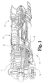
- FIG. 1 is a partially fragmented side elevational view of an industrial gas turbine engine including a combustor comprising one form of the present invention.
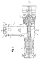
- FIG. 2 is an illustrative side elevational view of an industrial gas turbine engine including an external combustion system comprising one form of the present invention.
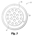
- FIG. 3 is an illustrative end view of the lean premix modules comprising a portion of the FIG.2 external combustion system.
- FIG. 4 is a perspective view of one form of the FIG. 1 combustor.
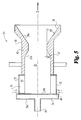
- FIG. 5 is an illustrative side view of one form of the lean premix module comprising a portion of the FIG. 2 external combustion system.
- FIG. 6 is a side elevational view of one form of the fuel tube comprising a portion of the lean premix module of FIG. 5.
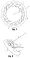
- FIG. 7 is an end view of one form of the radial swirler with fuel tubes comprising a portion of the lean premix module of FIG. 5.
- FIG. 8 is a partial end view of the radial swirler of FIG. 7.
- FIG. 9 is an illustrative side elevational view of one form of the FIG. 1 combustor with lean premix module.
- FIG. 10 is a side elevational view of one form of the fuel tube comprising a portion of the FIG. 9 lean premix module.
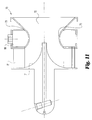
- FIG. 11 is an illustrative side elevational view of another form of the lean premix module comprising a portion of the FIG. 1 combustor.
- FIG. 12 is an end view of a radial swirler with swirler vanes having integral fuel passages comprising a portion of a lean premix module of the present invention.
- FIG. 1 there is illustrated a natural gas fueled industrial gas turbine engine 10.
- the industrial gas turbine engine illustrated in FIG. 1 is a single shaft model 501-K which is manufactured by Allison Engine Company of Indianapolis, Indiana. It is understood that other gas turbine engines could typically utilize at least one form of the the present invention.
- An industrial gas turbine engine 10 generally integrates a compressor 11, a combustor 12 and a power turbine 13. It is important to realize that there are a multitude of ways in which the components can be linked together. Additional compressors and turbines could be added with intercoolers connecting between the compressors and reheat combustion chambers could be added between the turbines.
- a combustion system 15 comprises six can type combustion liners 12 that are located in an annulus 16 formed by an outer and inner engine casing. It is understood that other inline combustion systems having a different quantity of can type liners are contemplated by this form of the present invention.
- Industrial gas turbine engines are used for electric power generation including stand by, continuous, and co-generation applications on land based, oil drilling rigs and ship board installations. Further, industrial gas turbine engines historically have been used to drive compressors in oil and gas recovery, and pipe line service systems as well as providing propulsion power for hydrofoil and conventional vessels.
- FIG. 2 there is illustrated a side elevational view of an industrial gas turbine engine 20 which integrates a compressor 21, a turbine 22 and a premix combustor 23.
- the silo combustor 23 is located off the centerline X of the engine, and the centerline Y of the combustor 23 is orthogonal to the centerline X of the compressor 21 and turbine 22.
- An off centerline silo combustor system allows for the size or volume of the combustor to be increased because there is no constraint on maintaining the combustor in the physical space between the compressor and the turbine. Additional combustor volume is advantageous for reducing carbon monoxide and unburned hydrocarbon emissions in premixed combustor systems.
- the schematic in FIG. 2 presents a gas turbine engine, model 501-K that is manufactured by Allison Engine Company, with an attached silo combustion system.
- the silo combustion system includes a plurality of lean premix modules 24. It is preferred that the number of lean premix modules located within the silo combustion system be within the range of about seven to 25, and it is most preferred that there are nineteen lean premix modules (FIG. 3) located within a single combustion liner 25.
- the interaction between the plurality of lean premix modules 24 reduces the recirculation zone associated with each module thereby reducing the formation of oxides of nitrogen.
- a catalytic reduction stage is added to convert oxides of nitrogen to nitrogen gas and ultimately lower the engine emissions.
- the lean premix modules 24 are closely packed into the dome 28 of the combustor, and this arrangement is generally referred to as parallel staging.
- the term dome as used herein is employed to define a chamber of any shape notwithstanding that dome is used in some other contexts to be limited to a hemispherical shape.
- All of the modules 24 receive a substantially similar volume of air at their inlet, while the number of modules supplied with fuel is governed by power requirements.
- the plurality of modules 24 are supplied with fuel in stages, that comprise several modules each in order to minimize the complexity of the fuel distribution network.
- the modules 24 are arranged in six stages with four modules in the first stage and three modules in each of the next five stages.
- the modules 24 are not in a staged mode. Further, it is contemplated in the present invention that the modules 24 are arranged in a series staging mode. Series staging involves spreading the modules out axially within the length of the single combustor liner.
- the air from compressor 21 is directed through a passageway to the combustor 23, such that it can be discharged between a combustor liner 25 and a combustor case 26.
- the air travels through an annular passageway 27 to the dome 28 of the combustor, and the flow of air is turned a maximum of 180 degrees before entering the combustion chamber.
- FIG. 4 there is illustrated a perspective view of one form of the inline combustor 12 with a lean premix module connected at the upstream end of the combustor.
- lean premix modules Several forms of lean premix modules will be described hereinafter and they are connectable to the combustor 12.
- the substantially cylindrical liner wall 30 of the combustion liner barrel 25 is cooled using either a backside convection cooling or effusion cooling. Both of these designs are generally well known to people skilled in the art and U.S. Patent No. 5,289,686 to Razdan provides added details thereon, and is incorporated herein by reference.
- the effusion cooled design includes providing several thousand small diameter holes 31 that are laser drilled at an acute angle with respect to the wall 30.
- the holes 31 are formed at an angle of 20 degrees with respect to the liner wall 30.
- the effusion hole pattern is optimized to produce uniform wall temperatures consistent with the design requirements for this liner.
- the inside surface of the combustion liner is coated with a thermal barrier ceramic coating. It is understood that other forms of the present invention utilize backside convention cooling, and that the combustion liner can be utilized without a thermal barrier ceramic coating.
- the premix module 24 is utilized to mix the fuel and air prior to delivery into a primary combustion zone within the combustion liner 25.
- the fuel is natural gas.
- the lean premix module 24 includes a plurality of fuel tubes 32, a fixed radial inflow swirler 33, a fuel manifold 34, a premixing chamber 35 and a nozzle 36.
- the nozzle 36 refers to the converging-diverging section of the module.
- Converging section 37 accelerates the flow of air and fuel to prevent a flame from within the primary combustion zone from flashing back into the premixing chamber 35.
- the converging section 37 includes an included angle of 60 degrees.
- Diverging section 38 which is separated from the converging section 37 by a throat 42, gradually expands and reduces the speed of the fuel and air mixture and induces a centrally located recirculation zone without the aid of a centerbody. It is desirable to produce a single central recirculation zone at the exit of the lean premixing module.
- the diverging section 38 has an included angle of about 70 degrees.
- Each of converging section 37 and diverging section 38 define a frustoconical surface 37a and 38a respectively.
- the central recirculation zone is located downstream from the diverging section 38 of nozzle 36.
- the fuel manifold 34 is located on the upstream end 24a of the module 24, and is connected to an external fuel source (not illustrated) though a fueling tube 39.
- Fuel manifold 34 has a plurality of apertures 40 formed in its downstream end 34b that are in fluid communication with the fuel tubes 32.
- the radial swirler 33 is fixidly attached to the module 24, and includes a plurality of flat swirler vanes 41 that extend parallel to the longitudinal centerline Z. As seen in FIG. 7, the flat swirler vanes 41 are angled toward the longitudinal centerline such that the inner edges form a restriction between adjacent vanes and a hollow core in the center of the swirler 33.
- the premixing chamber 35 being of a sufficient size and/or volume so as to not inhibit premixing, and in the preferred form defining a substantially cylindrical shape.
- the premixing chamber 35 and the nozzle 36 comprise an integral piece formed of a nickel alloy.
- a most preferred material is marketed by International Nickel Company of Huntington, West Virgina under the name HASTELLOY X ALLOY. Other materials having similar properties are contemplated by the present invention.
- the fuel tubes 32 are located between the vanes, and in the preferred embodiment the tubes having an outside diameter of 3/16 inches and include ten axially spaced 0.023 inch diameter fuel dispensing holes 43 therein.
- the fuel tubes have between 5 and 20 fuel dispensing holes for injecting the fuel into the incoming air stream that passes from the compressor. The fuel is dispensed from the fuel dispensing holes 43 such that it does not have sufficient momentum to penetrate the cross flow of air.
- FIG. 6 there is illustrated a preferred embodiment of fuel tube 32 wherein the fuel dispensing holes are located the following distances from the upstream end 32a: 'a' 0.275 inches; 'b' 0.475 inches; 'c' 0.725 inches; 'd' 1.075 inches; 'e' 1.375 inches; 'f' 0.375 inches; 'g' 0.575 inches; 'h' 0.875 inches; 'i' 1.175 inches; and 'j' 1.275 inches. It is understood that the radially inward flow of air through the radial swirler mixes with the fuel dispensed from the fuel dispensing holes 43 within the swirler 33.
- a majority of the premixing of fuel and air is done within the confines of the radial swirler 33. Further, it is understood by those skilled in the art that the changing of the location/orientation of the fuel dispensing holes 43 along the fuel tube 32 changes the fuel concentration profile at the outlet of the module 24.
- radial swirler 33 having a plurality of vanes 41 and showing the corresponding relationship to fuel tubes 32.
- radial swirler 33 includes sixteen flat solid vanes 41 that are spaced equally around the circumference of the swirler and connected between two end plates 44. The vanes are joined to the end plates 44 by commonly known assembly techniques such as brazing or cast as one piece.
- the vanes 41 being preferably inclined at an angle ⁇ , wherein angle ⁇ is most preferred to be about 42.5 degrees. It is understood that other angles are contemplated by the present invention, however it is understood that the degree of swirl is linked to the angle ⁇ and swirling of the fluid impacts the mixing and production of oxides of nitrogen.
- the fuel tubes 32 include fuel dispensing holes that are aligned in two rows and located on the radially inward side of the tubes.
- the fuel dispensing holes being located one hundred and twenty degrees apart, and oriented such that they are positioned sixty degrees fore and aft a radius 'R' that extends from the center of the radial swirler to the fuel tube 32. It is understood that other angles are contemplated, however the angle of inclination of the fuel dispensing holes 43 affects the fuel and air mixing during premixing.
- premix module 50 for use with an inline can-annular combustor 12.
- the lean premix module 50 is substantially identical to the premix module 24 that was described for use in a silo combustor, however premix module 50 is intended for use in an inline engine. Any significant differences between the modules are highlighted in the description of the preferred form of premix module 50.
- the lean premix module 50 includes a primary fuel manifold 51, a plurality of fuel tubes 52, a radial swirler 53, a nozzle 54 and a pilot fuel system 55.
- Premix module 50 utilizes a dual mode fuel delivery technique to meet pollutant emission requirements and engine operability requirements.
- premixed combustion and pilot diffusion combustion.
- Premixed combustion techniques mix the fuel and air prior to delivery into the primary combustion zone within the combustor.
- pilot diffusion combustion mode fuel is directly injected into the primary combustion zone by the pilot fuel system 55.
- the pilot combustion mode operates under a conventional diffusion flame technology that is well known to those skilled in the art.
- the primary fuel manifold 51 is connected to the upstream end 50a of the premix module 50 and provides fuel to the fuel tubes 52.
- Fuel tubes 52 extend axially along the radial swirler 53, and the fuel tubes 52 and radial swirler 53 are substantially similar to the fuel tubes 32 and swirler 33 of module 24. However, with reference to FIG. 10, there is illustrated the location of the fuel dispensing holes 56 that create the fuel concentration profile across the primary combustion zone.
- the fuel tubes 52 have an outside diameter of 3/16 inches and include nine 0.025 inch diameter fuel dispensing holes located a distance as follows from the upstream end: 'A' 0.425 inches; 'B' 0.625 inches; 'C' 0.825 inches; 'D' 0.975 inches; 'E' 1.050 inches; 'F' 1.125 inches; 'G' 1.275 inches; 'H' 1.425 inches; and 'I' 1.625 inches.
- the fuel tubes 52 being oriented relative to the vanes of the fixed radial swirler 53 analogously to the vanes 41 of radial swirler 33 (FIGS. 7 and 8). Further the mixing of the air and fuel is accomplished in the inter-vane spacing as well as in the straight section 65a of the throat 65.
- a pilot fuel manifold 57 is located in the trough between the fixed radial swirler 53 and the diverging section of the nozzle 60.
- the nozzle 60 includes a converging section 61 and a diverging section 62 that are separated by the throat 65. The functions of these sections are the same as for nozzle 36, however the nozzle 60 is connected directly to swirler 53 and there is an ellipsoidal transition from the swirler to the nozzle throat 65.
- the smooth ellipsoidal transition prevents any flow recirculation at sharp corners and minimizes or eliminates pressure drops across the transition. As can be seen from FIG.
- the diameter of the throat 65 is about 50% of the diameter of the upstream end of the barrel of combustor 12 and about 80% of the diameter of the diverging section 62 of the nozzle 60 at the exit of the premix module 50.
- the surface 65a of the throat is covered with a thick thermal barrier ceramic coating.
- the diverging section 62 of the nozzle includes a seventy degree included angle, and thereafter the flow of fuel and air undergoes a sudden expansion to the diameter of the combustor liner. This sudden expansion creates a sheltered annular zone 65 into which the pilot fuel is introduced through the twelve pilot tubes 66.
- the pilot tubes 66 being oriented at an acute angle to the liner wall and being spaced equally around the circumference of the module.
- a downstream surface 66 of the module 50 which is exposed to the hot gases in the sheltered annular zone 65 are air cooled by the passing of air through about two hundred and fifty effusion cooling holes that are laser drilled at a thirty degree angle to surface 66.
- Lean premix module 70 includes a central fuel pilot 71 that supplies fuel to the central recirculation zone 72 for providing stability during operation in the lean premix mode.
- the lean premix module 70 includes a nozzle 73 having a converging and diverging section with a throat 75 therebetween.
- the diverging section forms an included angle of 70 degrees and expands out further than in module 50, because the center fuel pilot 71 eliminates the necessity of having a sheltered region for receiving pilot fuel. As shown in FIG.
- the diameter of the throat 75 is about 50% of the diameter of the diverging portion of the nozzle 73 adjacent the exit of the premix module.
- the main fuel manifold 80 being positioned in the trough between the fixed radial swirler 81 and the nozzle 73.
- a radial swirler 90 having a plurality of vanes 91 with integral cylindrical fuel passages 92 and 93.
- the fixed radial swirler 90 being adapted for use in the previously described lean premix modules.
- the sixteen vanes 91 are of a triangular cross section and the air flows between the parallel sides of the adjacent vanes.
- the two fuel passages 92 and 93 allow for the dispensing of fuel on either side of the vane into the moving air.
- the fuel distribution apertures are spaced axially along the vanes in order to control the dispensing of fuel and the corresponding fuel concentration profile.
- the fuel dispensing passages 92 and 93 are connected to separate fuel manifolds, which allows the fuel distribution from each passage to be controlled during operation.
Landscapes
- Engineering & Computer Science (AREA)
- Chemical & Material Sciences (AREA)
- Combustion & Propulsion (AREA)
- Mechanical Engineering (AREA)
- General Engineering & Computer Science (AREA)
Abstract
Description
- The present invention relates generally to gas turbine engine combustors, and more particularly in one form of the present invention to a lean premix module which significantly reduces emissions of oxides of nitrogen while maintaining low emission levels of unburned hydrocarbons and carbon monoxide.
- Air polluting emissions are an undesirable by-product from the operation of a gas turbine engine that burns fossil fuels. The primary air polluting emissions produced by the burning of fossil fuels include carbon dioxide, water vapor, oxides of nitrogen, carbon monoxide, unburned hydrocarbons, oxides of sulfur and particulates. Of the above emissions, carbon dioxide and water vapor are generally not considered objectionable. However, air pollution has become a worldwide concern and many countries have enacted stricter laws restricting the discharge of the pollutants from a gas turbine engine.
- Gas turbine engine designers generally accept that many of the by-products of the combustion of a fossil fuel can be controlled by design modifications, cleanup of exhaust gases and/or regulating the quality of fuel. For example, the emission of particulates in exhaust gas have been controlled by design modifications to the combustors and fuel injectors, or by removing the particulates with traps and filters. The selection of fuels that are low in total sulfur content is a generally accepted method to control the discharge of sulfur oxides. Therefore the remaining polluting emissions of primary concern in the exhaust gases are oxides of nitrogen and unburned hydrocarbons.
- The principal mechanism for the formation of oxides of nitrogen involves the direct oxidation of nitrogen and oxygen, and the chemical reaction producing this by-product occurs at a rate that is an exponential function of temperature. It is well known that in a gas turbine engine the oxidation of nitrogen is dependent upon the temperature in the primary combustion zone. Consequently, a small reduction in temperature within the combustor can result in a relatively large reduction in the emission of oxides of nitrogen. Further, in the traditional combustor, regions exist in the primary combustion zone that have stoichiometric mixtures with attendant high gas temperatures that enhance stability and combustion efficiency at the expense of oxides of nitrogen, carbon monoxide and unburned hydrocarbons production.
- Until recently, a common technique for reducing the emission of oxides of nitrogen from a gas turbine engine involved reducing the flame temperature in the primary combustion zone of the combustor, such as through diluent injection which involves injecting large amounts of water or steam directly into the primary combustion zone. Diluent injection reduces the high temperatures that are produced in the stoichiometric regions of the current diffusion flame type combustors and the reduced temperatures reduce the formation of oxides of nitrogen. Unfortunately the lower temperatures slow the oxidation processes that are responsible for destroying unburned hydrocarbons and carbon monoxide thereby increasing their emission levels. Further, diluent injection also negatively impacts combustor and turbine durability and a fuel consumption penalty is incurred.
- While diluent injection has been utilized to reduce the formation of oxides of nitrogen, a second technique selective catalytic reduction has been utilized to convert the oxides of nitrogen into nitrogen gas after it is formed. Both of these prior techniques have the disadvantages of added complexity, high installation costs, high operating costs and reduced engine reliability.
- Most recently, gas turbine engine designers and manufacturers have generally adopted a lean premix combustion technique to reduce the pollutant emissions from the engine by altering the basic combustion process where the pollutants are formed, thereby making the combustion process inherently clean. In lean premix combustion the fuel and air are premixed to a fuel lean proportion prior to combustion. The premixing of the fuel and air in this fashion avoids the high temperature stoichiometric fuel air mixtures which yields the corresponding highest flame temperatures, and therefore the formation rate of oxides of nitrogen, which is exponentially dependent, on temperature is lowered.
- Although the prior techniques for reducing the emissions of oxides of nitrogen from gas turbine engines are steps in the right direction, the need for additional improvements still remain. The present invention satisfies this need in a novel and unobvious way.
- One form of the present invention contemplates a combination, comprising: a gas turbine engine; a silo combustor connected to the gas turbine engine, the silo combustor being connected to the gas turbine engine off the centerline of the gas turbine engine, and the combustor having a dome; and a plurality of lean premix modules positioned within the dome of the silo combustor, each of the lean premix modules comprising: a fixed radial swirler; a plurality of fuel passages positioned axially along the radial swirler for dispensing fuel to be mixed with a flow of air passing through the swirler; and a nozzle in fluid communication with the swirler,the nozzle having a converging portion for accelerating the flow of mixed fuel and air to prevent flashback into the lean premix module, and the nozzle having a diverging portion connected downstream from the converging portion for expanding the flow of fuel and air and inducing a centrally located recirculation zone.
- One object of the present invention is to provide an improved combustor for a gas turbine engine.
- Related objects and advantages of the present invention will be apparent from the following description.
- FIG. 1 is a partially fragmented side elevational view of an industrial gas turbine engine including a combustor comprising one form of the present invention.
- FIG. 2 is an illustrative side elevational view of an industrial gas turbine engine including an external combustion system comprising one form of the present invention.
- FIG. 3 is an illustrative end view of the lean premix modules comprising a portion of the FIG.2 external combustion system.
- FIG. 4 is a perspective view of one form of the FIG. 1 combustor.
- FIG. 5 is an illustrative side view of one form of the lean premix module comprising a portion of the FIG. 2 external combustion system.
- FIG. 6 is a side elevational view of one form of the fuel tube comprising a portion of the lean premix module of FIG. 5.
- FIG. 7 is an end view of one form of the radial swirler with fuel tubes comprising a portion of the lean premix module of FIG. 5.
- FIG. 8 is a partial end view of the radial swirler of FIG. 7.
- FIG. 9 is an illustrative side elevational view of one form of the FIG. 1 combustor with lean premix module.
- FIG. 10 is a side elevational view of one form of the fuel tube comprising a portion of the FIG. 9 lean premix module.
- FIG. 11 is an illustrative side elevational view of another form of the lean premix module comprising a portion of the FIG. 1 combustor.
- FIG. 12 is an end view of a radial swirler with swirler vanes having integral fuel passages comprising a portion of a lean premix module of the present invention.
- For the purposes of promoting an understanding of the principles of the invention, reference will now be made to the embodiment illustrated in the drawings and specific language will be used to describe the same. It will nevertheless be understood that no limitation of the scope of the invention is thereby intended, such alterations and further modifications in the illustrated device, and such further applications of the principles of the invention as illustrated therein being contemplated as would normally occur to one skilled in the art to which the invention relates.
- Referring to FIG. 1, there is illustrated a natural gas fueled industrial
gas turbine engine 10. The industrial gas turbine engine illustrated in FIG. 1 is a single shaft model 501-K which is manufactured by Allison Engine Company of Indianapolis, Indiana. It is understood that other gas turbine engines could typically utilize at least one form of the the present invention. An industrialgas turbine engine 10 generally integrates acompressor 11, acombustor 12 and apower turbine 13. It is important to realize that there are a multitude of ways in which the components can be linked together. Additional compressors and turbines could be added with intercoolers connecting between the compressors and reheat combustion chambers could be added between the turbines. - In one form of the present invention a
combustion system 15 comprises six cantype combustion liners 12 that are located in anannulus 16 formed by an outer and inner engine casing. It is understood that other inline combustion systems having a different quantity of can type liners are contemplated by this form of the present invention. Industrial gas turbine engines are used for electric power generation including stand by, continuous, and co-generation applications on land based, oil drilling rigs and ship board installations. Further, industrial gas turbine engines historically have been used to drive compressors in oil and gas recovery, and pipe line service systems as well as providing propulsion power for hydrofoil and conventional vessels. - With reference to FIG. 2, there is illustrated a side elevational view of an industrial
gas turbine engine 20 which integrates acompressor 21, aturbine 22 and apremix combustor 23. In one form of thegas turbine engine 20 thesilo combustor 23 is located off the centerline X of the engine, and the centerline Y of thecombustor 23 is orthogonal to the centerline X of thecompressor 21 andturbine 22. An off centerline silo combustor system allows for the size or volume of the combustor to be increased because there is no constraint on maintaining the combustor in the physical space between the compressor and the turbine. Additional combustor volume is advantageous for reducing carbon monoxide and unburned hydrocarbon emissions in premixed combustor systems. - The schematic in FIG. 2 presents a gas turbine engine, model 501-K that is manufactured by Allison Engine Company, with an attached silo combustion system. The silo combustion system includes a plurality of
lean premix modules 24. It is preferred that the number of lean premix modules located within the silo combustion system be within the range of about seven to 25, and it is most preferred that there are nineteen lean premix modules (FIG. 3) located within asingle combustion liner 25. The interaction between the plurality oflean premix modules 24 reduces the recirculation zone associated with each module thereby reducing the formation of oxides of nitrogen. Further, in another form of combustor 23 a catalytic reduction stage is added to convert oxides of nitrogen to nitrogen gas and ultimately lower the engine emissions. - In the preferred form of
combustor 23 thelean premix modules 24 are closely packed into thedome 28 of the combustor, and this arrangement is generally referred to as parallel staging. The term dome as used herein is employed to define a chamber of any shape notwithstanding that dome is used in some other contexts to be limited to a hemispherical shape. All of themodules 24 receive a substantially similar volume of air at their inlet, while the number of modules supplied with fuel is governed by power requirements. The plurality ofmodules 24 are supplied with fuel in stages, that comprise several modules each in order to minimize the complexity of the fuel distribution network. In the preferred form ofcombustor 23 themodules 24 are arranged in six stages with four modules in the first stage and three modules in each of the next five stages. In an alternative form of thecombustor 23 themodules 24 are not in a staged mode. Further, it is contemplated in the present invention that themodules 24 are arranged in a series staging mode. Series staging involves spreading the modules out axially within the length of the single combustor liner. - In
gas turbine engine 20 the air fromcompressor 21 is directed through a passageway to thecombustor 23, such that it can be discharged between acombustor liner 25 and acombustor case 26. The air travels through anannular passageway 27 to thedome 28 of the combustor, and the flow of air is turned a maximum of 180 degrees before entering the combustion chamber. - Referring to FIG. 4, there is illustrated a perspective view of one form of the
inline combustor 12 with a lean premix module connected at the upstream end of the combustor. Several forms of lean premix modules will be described hereinafter and they are connectable to thecombustor 12. The substantiallycylindrical liner wall 30 of thecombustion liner barrel 25 is cooled using either a backside convection cooling or effusion cooling. Both of these designs are generally well known to people skilled in the art and U.S. Patent No. 5,289,686 to Razdan provides added details thereon, and is incorporated herein by reference. The effusion cooled design includes providing several thousand small diameter holes 31 that are laser drilled at an acute angle with respect to thewall 30. In the preferred embodiment ofcylindrical liner 30 the holes 31 are formed at an angle of 20 degrees with respect to theliner wall 30. The effusion hole pattern is optimized to produce uniform wall temperatures consistent with the design requirements for this liner. Further, the inside surface of the combustion liner is coated with a thermal barrier ceramic coating. It is understood that other forms of the present invention utilize backside convention cooling, and that the combustion liner can be utilized without a thermal barrier ceramic coating. - With reference to FIG. 5, there is illustrated an enlarged side elevational view of the
lean premix module 24. Thepremix module 24 is utilized to mix the fuel and air prior to delivery into a primary combustion zone within thecombustion liner 25. In the preferred embodiment the fuel is natural gas. Thelean premix module 24 includes a plurality offuel tubes 32, a fixedradial inflow swirler 33, afuel manifold 34, a premixingchamber 35 and anozzle 36. Thenozzle 36 refers to the converging-diverging section of the module. Convergingsection 37 accelerates the flow of air and fuel to prevent a flame from within the primary combustion zone from flashing back into the premixingchamber 35. In the preferred embodiment the convergingsection 37 includes an included angle of 60 degrees. It is preferred that the fluid flow be accelerated to a rate of about 250 ft/sec. Divergingsection 38, which is separated from the convergingsection 37 by athroat 42, gradually expands and reduces the speed of the fuel and air mixture and induces a centrally located recirculation zone without the aid of a centerbody. It is desirable to produce a single central recirculation zone at the exit of the lean premixing module. The divergingsection 38 has an included angle of about 70 degrees. Each of convergingsection 37 and divergingsection 38 define afrustoconical surface section 38 ofnozzle 36. - The
fuel manifold 34 is located on theupstream end 24a of themodule 24, and is connected to an external fuel source (not illustrated) though a fuelingtube 39.Fuel manifold 34 has a plurality ofapertures 40 formed in itsdownstream end 34b that are in fluid communication with thefuel tubes 32. Theradial swirler 33 is fixidly attached to themodule 24, and includes a plurality offlat swirler vanes 41 that extend parallel to the longitudinal centerline Z. As seen in FIG. 7, theflat swirler vanes 41 are angled toward the longitudinal centerline such that the inner edges form a restriction between adjacent vanes and a hollow core in the center of theswirler 33. The premixingchamber 35 being of a sufficient size and/or volume so as to not inhibit premixing, and in the preferred form defining a substantially cylindrical shape. In the preferred embodiment the premixingchamber 35 and thenozzle 36 comprise an integral piece formed of a nickel alloy. A most preferred material is marketed by International Nickel Company of Huntington, West Virgina under the name HASTELLOY X ALLOY. Other materials having similar properties are contemplated by the present invention. - With reference to FIGS 6-8, there is illustrated further detail regarding the components that form the
premix module 24. Thefuel tubes 32 are located between the vanes, and in the preferred embodiment the tubes having an outside diameter of 3/16 inches and include ten axially spaced 0.023 inch diameter fuel dispensing holes 43 therein. In alternate forms of the present invention the fuel tubes have between 5 and 20 fuel dispensing holes for injecting the fuel into the incoming air stream that passes from the compressor. The fuel is dispensed from the fuel dispensing holes 43 such that it does not have sufficient momentum to penetrate the cross flow of air. - With particular reference to FIG. 6 there is illustrated a preferred embodiment of
fuel tube 32 wherein the fuel dispensing holes are located the following distances from theupstream end 32a: 'a' 0.275 inches; 'b' 0.475 inches; 'c' 0.725 inches; 'd' 1.075 inches; 'e' 1.375 inches; 'f' 0.375 inches; 'g' 0.575 inches; 'h' 0.875 inches; 'i' 1.175 inches; and 'j' 1.275 inches. It is understood that the radially inward flow of air through the radial swirler mixes with the fuel dispensed from the fuel dispensing holes 43 within theswirler 33. A majority of the premixing of fuel and air is done within the confines of theradial swirler 33. Further, it is understood by those skilled in the art that the changing of the location/orientation of the fuel dispensing holes 43 along thefuel tube 32 changes the fuel concentration profile at the outlet of themodule 24. - Referring to FIGS. 7 and 8, there is illustrated the
radial swirler 33 having a plurality ofvanes 41 and showing the corresponding relationship to fueltubes 32. In the preferred embodimentradial swirler 33 includes sixteen flatsolid vanes 41 that are spaced equally around the circumference of the swirler and connected between twoend plates 44. The vanes are joined to theend plates 44 by commonly known assembly techniques such as brazing or cast as one piece. Thevanes 41 being preferably inclined at an angle φ, wherein angle φ is most preferred to be about 42.5 degrees. It is understood that other angles are contemplated by the present invention, however it is understood that the degree of swirl is linked to the angle φ and swirling of the fluid impacts the mixing and production of oxides of nitrogen. - The
fuel tubes 32 include fuel dispensing holes that are aligned in two rows and located on the radially inward side of the tubes. The fuel dispensing holes being located one hundred and twenty degrees apart, and oriented such that they are positioned sixty degrees fore and aft a radius 'R' that extends from the center of the radial swirler to thefuel tube 32. It is understood that other angles are contemplated, however the angle of inclination of the fuel dispensing holes 43 affects the fuel and air mixing during premixing. - With reference to FIG. 9, there is illustrated another form of a premix module for use with an inline can-
annular combustor 12. Thelean premix module 50 is substantially identical to thepremix module 24 that was described for use in a silo combustor, however premixmodule 50 is intended for use in an inline engine. Any significant differences between the modules are highlighted in the description of the preferred form ofpremix module 50. Thelean premix module 50 includes aprimary fuel manifold 51, a plurality offuel tubes 52, aradial swirler 53, a nozzle 54 and apilot fuel system 55.Premix module 50 utilizes a dual mode fuel delivery technique to meet pollutant emission requirements and engine operability requirements. The modes of combustion related to this dual fuel delivery technique are generally referred to as premixed combustion, and pilot diffusion combustion. Premixed combustion techniques mix the fuel and air prior to delivery into the primary combustion zone within the combustor. During the pilot diffusion combustion mode fuel is directly injected into the primary combustion zone by thepilot fuel system 55. The pilot combustion mode operates under a conventional diffusion flame technology that is well known to those skilled in the art. - The
primary fuel manifold 51 is connected to theupstream end 50a of thepremix module 50 and provides fuel to thefuel tubes 52.Fuel tubes 52 extend axially along theradial swirler 53, and thefuel tubes 52 andradial swirler 53 are substantially similar to thefuel tubes 32 andswirler 33 ofmodule 24. However, with reference to FIG. 10, there is illustrated the location of the fuel dispensing holes 56 that create the fuel concentration profile across the primary combustion zone. Thefuel tubes 52 have an outside diameter of 3/16 inches and include nine 0.025 inch diameter fuel dispensing holes located a distance as follows from the upstream end: 'A' 0.425 inches; 'B' 0.625 inches; 'C' 0.825 inches; 'D' 0.975 inches; 'E' 1.050 inches; 'F' 1.125 inches; 'G' 1.275 inches; 'H' 1.425 inches; and 'I' 1.625 inches. Thefuel tubes 52 being oriented relative to the vanes of the fixedradial swirler 53 analogously to thevanes 41 of radial swirler 33 (FIGS. 7 and 8). Further the mixing of the air and fuel is accomplished in the inter-vane spacing as well as in thestraight section 65a of thethroat 65. - A
pilot fuel manifold 57 is located in the trough between the fixedradial swirler 53 and the diverging section of thenozzle 60. Thenozzle 60 includes a convergingsection 61 and a divergingsection 62 that are separated by thethroat 65. The functions of these sections are the same as fornozzle 36, however thenozzle 60 is connected directly toswirler 53 and there is an ellipsoidal transition from the swirler to thenozzle throat 65. The smooth ellipsoidal transition prevents any flow recirculation at sharp corners and minimizes or eliminates pressure drops across the transition. As can be seen from FIG. 9, the diameter of thethroat 65 is about 50% of the diameter of the upstream end of the barrel ofcombustor 12 and about 80% of the diameter of the divergingsection 62 of thenozzle 60 at the exit of thepremix module 50. In one form of thenozzle 60 thesurface 65a of the throat is covered with a thick thermal barrier ceramic coating. - The diverging
section 62 of the nozzle includes a seventy degree included angle, and thereafter the flow of fuel and air undergoes a sudden expansion to the diameter of the combustor liner. This sudden expansion creates a shelteredannular zone 65 into which the pilot fuel is introduced through the twelve pilot tubes 66. The pilot tubes 66 being oriented at an acute angle to the liner wall and being spaced equally around the circumference of the module. A downstream surface 66 of themodule 50 which is exposed to the hot gases in the shelteredannular zone 65 are air cooled by the passing of air through about two hundred and fifty effusion cooling holes that are laser drilled at a thirty degree angle to surface 66. - Referring to FIG. 11, there is illustrated another form of a lean premix module that is substantially identical to
lean premix module 50. A significant difference is being attributed to the location of the pilot fuel system.Lean premix module 70 includes acentral fuel pilot 71 that supplies fuel to thecentral recirculation zone 72 for providing stability during operation in the lean premix mode. Thelean premix module 70 includes anozzle 73 having a converging and diverging section with athroat 75 therebetween. The diverging section forms an included angle of 70 degrees and expands out further than inmodule 50, because thecenter fuel pilot 71 eliminates the necessity of having a sheltered region for receiving pilot fuel. As shown in FIG. 11, the diameter of thethroat 75 is about 50% of the diameter of the diverging portion of thenozzle 73 adjacent the exit of the premix module. Themain fuel manifold 80 being positioned in the trough between the fixedradial swirler 81 and thenozzle 73. - With reference to FIG 12, there is illustrated a
radial swirler 90 having a plurality ofvanes 91 with integralcylindrical fuel passages radial swirler 90 being adapted for use in the previously described lean premix modules. The sixteenvanes 91 are of a triangular cross section and the air flows between the parallel sides of the adjacent vanes. The twofuel passages fuel dispensing passages - While the invention has been illustrated and described in detail in the drawings and foregoing description, the same is to be considered as illustrative and not restrictive in character, it being understood that only the preferred embodiment has been shown and described and that all changes and modifications that come within the spirit of the invention are desired to be protected.
Claims (44)
- A gas turbine engine including a combustor having a plurality of lean premix modules, all of said modules positioned on the same side of said gas turbine engine, each of said modules comprising a radial swirler.
- A gas turbine engine according to claim 1, wherein said plurality of lean premix modules number between seven and twenty-five.
- A gas turbine engine according to claim 2, wherein said plurality of lean premix modules number about twenty.
- A gas turbine engine according to any preceding claim, wherein said swirler is a radial inflow swirler.
- A gas turbine engine according to any preceding claim, wherein said swirler is fixed relative to said premix module and includes a plurality of vanes.
- A gas turbine engine according to any preceding claim, wherein said swirler has a hollow core.
- A gas turbine engine according to any preceding claim, wherein said swirler has an inlet; and each of said premix modules further comprises a fueling pathway positioned axially along said swirler and having an outlet located adjacent said inlet of said swirler.
- A combustor assembly including a plurality of premix modules having substantially parallel centerlines, each of said modules comprising a radial swirler fixed relative to said module and having a plurality of vanes, all of said vanes terminating at a same axial location.
- A combustor assembly comprising:a single combustor chamber; andseveral premix modules exiting into said single combustor chamber, each of said modules comprising:a radial swirler; anda nozzle in flow communication with said swirler and in flow communication with said combustor chamber.
- A combustor assembly according to claim 8 or claim 9, wherein said swirler is a radial inflow swirler.
- A combustor assembly according to any one of claims 8 to 10, wherein said swirler is fixed relative to said premix module and includes a plurality of vanes.
- A combustor assembly according to any one of claims 8 to 11, wherein said swirler has a hollow core.
- A combustor assembly according to any one of claims 8 to 12, wherein said swirler has an inlet; andeach of said premix modules further comprises a fueling pathway positioned along said swirler and having an outlet located adjacent said inlet of said swirler.
- A combustor assembly for receiving fuel from an external source and air from a compressor, comprising:a combustor having a dome; anda plurality of lean premix modules positioned within said dome, each of said modules comprising:a radial swirler fixed relative to said module and having an upstream end, and inlet, and a plurality of vanes, all of said vanes terminating at a same axial location; anda fueling pathway positioned axially along said radial swirler for delivering fuel across said sirler, said fueling pathway having an outlet located adjacent said inlet of said swirler.
- A combustor assembly for receiving fuel from an external source and air from a compressor, comprising;a combustion housing having an upstream end; anda lean premix module connected to said upstream end of said combustion housing, said module comprising:a radial swirler fixed relative to said module and having an upstream end, an inlet, and a plurality of vanes, all of said vanes terminating at a same axial location; anda fueling pathway positioned axially along said swirler for delivering fuel across said swirler, said fueling pathway having an outlet located adjacent said inlet of said swirler.
- A combustor assembly according to claim 14 or claim 15, wherein said fueling pathway includes a plurality of fuel passages each of said fuel passages having a downstream side and fuel dispensing holes located on said downstream side and distributed axially along said fuel passages.
- A combustor assembly according to claim 16, wherein said radial swirler has a centerline, andeach of said fuel passages has a fore array of fuel dispensing holes located fore a line extending from said fuel passage to said centerline of said swirler and an aft array of fuel dispensing holes located aft said line.
- A combustor assembly according to claim 17, wherein each of said fuel passages has an axial midpoint; said fuel dispensing holes of said aft array are distributed substantially uniformly along each of said fuel passages; and said fuel dispensing holes of said fore array are distributed primarily downstream of said axial midpoint of each of said fuel passages.
- A combustor assembly according to claim 17 or claim 18, wherein said fore array is located about 60° fore said line extending from said fuel passage to said centerline of said swirler; and said aft array is located about 60° aft said line.
- A combustor assembly according to claim 14 or claim 15, wherein each of said vanes of said radial swirler has holes therein; andsaid fueling pathway includes fuel passages formed integral with and extending axially within said vanes of said radial swirler, said fuel passages in flow communication with said holes of said vanes.
- A combustor assembly according to claim 20, wherein said holes of each of said vanes includes a first plurality of holes and a second plurality of holes; andsaid fuel passages of said fuel pathway includes a first plurality of fuel passages in flow communication with said first plurality of holes and a second plurality of fuel passages in flow communication with said second plurality of holes.
- A combustor assembly according to claim 21, further comprising a first fuel manifold connected to said first plurality of fuel passages, and a second fuel manifold connected to said second plurality of fuel passages for independently controlling the fuel dispensed from said first plurality of fuel passages and the fuel dispensed from said second plurality of fuel passages.
- A combustor assembly according to any one of claims 14 to 19, wherein said vanes of said radial swirler are flat and solid.
- A combustor assembly according to any one of claims 14, 15, 20, 21 or 22, wherein each of said vanes has a generally triangular cross section.
- A combustor assembly according to any one of claims 14 to 24, wherein said radial swirler has a centerline; andeach of said vanes of said swirler has a leading edge and is inclined about 40° to a line extending from said leading edge of said vane to said centerline of said swirler.
- A combustor assembly for receiving fuel from an external source and air from a compressor, comprising:a combustor having a dome; anda plurality of lean premix modules positioned within said dome, each of said modules having a radial swirler with a hollow core.
- A combustor assembly for receiving fuel from an external source and air from a compressor, comprising:a combustion housing having an upstream end; anda lean premix module connected to said upstream end of said combustion housing, said module having a radial swirler with a hollow core.
- A combustor assembly according to claim 26 or claim 27, wherein the or each said lean premix module further comprises a nozzle downstream of and in flow communication with said radial swirler, said nozzle having a converging section for accelerating the flow of mixed fuel and air to inhibit flashback into a respective module, and said nozzle having a diverging section downstream from said converging section for expanding the flow of fuel and air.
- A combustor assembly according to claim 28, wherein said nozzle further includes a throat positioned between said converging section and said diverging section, said throat having a thermal barrier ceramic coating deposited thereon.
- A combustor assembly according to claim 28 or claim 29, wherein said converging section is a smooth ellipsoidal transition.
- A combustor assembly for receiving a flow of fuel from an external source and a flow of air from a compressor, comprising:a combustor having a dome: anda plurality of premix modules positioned within said dome, each of said modules comprising:a radial swirler having an inlet, an outlet, and a downstream end;a premixing chamber connected to said downstream end of said radial swirler, said premixing chamber having an inner surface with a diameter that is substantially the same as the diameter of said swirler at said outlet.
- A combustor assembly according to claim 31, wherein said radial swirler is fixed relative to said premix module and includes a plurality of vanes.
- A combustor assembly according to claim 32, wherein each of said vanes of said swirler has apertures therein; and each of said premix modules further includes a plurality of fuel passages formed integral with said vanes and in flow communication with said apertures.
- A combustor assembly according to any one of claims 31 to 33, wherein each of said premix modules further includes a plurality of fuel tubes extending axially along said radial swirler and located adjacent said inlet of said swirler, each of said fuel tubes having an outlet.
- A combustor assembly according to claim 34, wherein each of said fuel tubes further includes a radially inward side; and said outlet of each of said fuel tubes further comprises a plurality of fuel holes located on said radially inward side of said fuel tube.
- A combustor assembly according to any one of claims 31 to 35, wherein each of said premix modules further comprises a nozzle positioned downstream of and in flow communication with said premixing chamber, said nozzle having a converging section and a diverging section located downstream of said converging section.
- A combustor assembly according to any one of claims 28, 29, 30 and 36, wherein said converging section has an included angle of about 60°.
- A combustor assembly according to any one of claims 28, 29, 30, 35 and 36, wherein said diverging section has an included angle of about 70°
- A combustor assembly for receiving fuel from an external source and air from a compressor, comprising:a combustion barrel having an upstream end; anda lean premix module having a downstream end connected to said upstream end of said combustion barrel, said premix module comprising:a radial swirler;a nozzle downstream of and in flow communication with said swirler, said nozzle having a converging section for accelerating the flow of mixed fuel and air, a diverging section for expanding the flow, and a throat positioned therebetween, said throat of said nozzle having a diameter about 50% of the diameter of said combustion barrel measured at said upstream end.
- A combustor assembly according to claim 39, wherein said premix module further includes an exit located at its downstream end; and said diameter of said throat is about 80% of the diameter of said diverging section measured at said exit.
- A combustor assembly according to claim 39, wherein said diameter of said throat is about 50% of the diameter of said diverging section measured at said exit.
- A combustor assembly according to any one of claims 39 to 41, wherein said radial swirler has a hollow core.
- A combustor assembly according to any one of claims 39 to 42, wherein said swirler has a core; and said premix module further comprises a fuel pilot projecting axially into said core.
- A premix module comprising an inlet capable of receiving air from substantially a 360° periphery, an exit, means for injecting fuel into air immediately at the periphery of said inlet, means for blending the flow of fuel and air substantially uniformly without producing local regions of adverse flow, means for accelerating the flow of fuel and air toward said exit, and means for inducing a single recirculation zone downstream of said exit of said module without the aid of a centerbody.
Applications Claiming Priority (2)
| Application Number | Priority Date | Filing Date | Title |
|---|---|---|---|
| US46452695A | 1995-06-05 | 1995-06-05 | |
| US464526 | 1995-06-05 |
Publications (3)
| Publication Number | Publication Date |
|---|---|
| EP0747635A2 true EP0747635A2 (en) | 1996-12-11 |
| EP0747635A3 EP0747635A3 (en) | 1998-09-02 |
| EP0747635B1 EP0747635B1 (en) | 2003-01-15 |
Family
ID=23844285
Family Applications (1)
| Application Number | Title | Priority Date | Filing Date |
|---|---|---|---|
| EP96304161A Expired - Lifetime EP0747635B1 (en) | 1995-06-05 | 1996-06-05 | Dry low oxides of nitrogen lean premix module for industrial gas turbine engines |
Country Status (4)
| Country | Link |
|---|---|
| US (1) | US6094916A (en) |
| EP (1) | EP0747635B1 (en) |
| JP (1) | JPH09119641A (en) |
| DE (1) | DE69625744T2 (en) |
Cited By (13)
| Publication number | Priority date | Publication date | Assignee | Title |
|---|---|---|---|---|
| EP0916894A1 (en) * | 1997-11-13 | 1999-05-19 | Abb Research Ltd. | Burner for operating a heat generator |
| EP0918191A1 (en) * | 1997-11-21 | 1999-05-26 | Abb Research Ltd. | Burner for the operation of a heat generator |
| EP1235033A3 (en) * | 2001-02-22 | 2003-10-08 | ALSTOM (Switzerland) Ltd | Annular combustor and method of operating the same |
| EP1852656A1 (en) | 2006-04-04 | 2007-11-07 | Nauchno-proizvodstvennoe predpriatie "EST" | Method for fuel combustion and combustion apparatus |
| EP1921376A1 (en) * | 2006-11-08 | 2008-05-14 | Siemens Aktiengesellschaft | Fuel injection system |
| WO2014099090A3 (en) * | 2012-10-01 | 2014-08-21 | Alstom Technology Ltd. | Combustor with radially staged premixed pilot for improved operability |
| US8925323B2 (en) | 2012-04-30 | 2015-01-06 | General Electric Company | Fuel/air premixing system for turbine engine |
| EP3098514A1 (en) * | 2015-05-29 | 2016-11-30 | Siemens Aktiengesellschaft | Combustor arrangement |
| CN107525095A (en) * | 2017-07-24 | 2017-12-29 | 西北工业大学 | A kind of axially staged can burner of gas turbine |
| CN107559882A (en) * | 2017-07-24 | 2018-01-09 | 西北工业大学 | A kind of axially staged low pollution combustor |
| US9897317B2 (en) | 2012-10-01 | 2018-02-20 | Ansaldo Energia Ip Uk Limited | Thermally free liner retention mechanism |
| US10060630B2 (en) | 2012-10-01 | 2018-08-28 | Ansaldo Energia Ip Uk Limited | Flamesheet combustor contoured liner |
| US10378456B2 (en) | 2012-10-01 | 2019-08-13 | Ansaldo Energia Switzerland AG | Method of operating a multi-stage flamesheet combustor |
Families Citing this family (107)
| Publication number | Priority date | Publication date | Assignee | Title |
|---|---|---|---|---|
| US6374594B1 (en) * | 2000-07-12 | 2002-04-23 | Power Systems Mfg., Llc | Silo/can-annular low emissions combustor |
| US6718772B2 (en) | 2000-10-27 | 2004-04-13 | Catalytica Energy Systems, Inc. | Method of thermal NOx reduction in catalytic combustion systems |
| US7121097B2 (en) | 2001-01-16 | 2006-10-17 | Catalytica Energy Systems, Inc. | Control strategy for flexible catalytic combustion system |
| US6508061B2 (en) * | 2001-04-25 | 2003-01-21 | Pratt & Whitney Canada Corp | Diffuser combustor |
| FR2824625B1 (en) * | 2001-05-10 | 2003-08-15 | Inst Francais Du Petrole | DEVICE AND METHOD FOR INJECTING A LIQUID FUEL INTO AN AIRFLOW FOR A COMBUSTION CHAMBER |
| US6796129B2 (en) | 2001-08-29 | 2004-09-28 | Catalytica Energy Systems, Inc. | Design and control strategy for catalytic combustion system with a wide operating range |
| US6691515B2 (en) | 2002-03-12 | 2004-02-17 | Rolls-Royce Corporation | Dry low combustion system with means for eliminating combustion noise |
| DE10219354A1 (en) * | 2002-04-30 | 2003-11-13 | Rolls Royce Deutschland | Gas turbine combustion chamber with targeted fuel introduction to improve the homogeneity of the fuel-air mixture |
| US6832481B2 (en) * | 2002-09-26 | 2004-12-21 | Siemens Westinghouse Power Corporation | Turbine engine fuel nozzle |
| US20040255588A1 (en) * | 2002-12-11 | 2004-12-23 | Kare Lundberg | Catalytic preburner and associated methods of operation |
| US6868676B1 (en) | 2002-12-20 | 2005-03-22 | General Electric Company | Turbine containing system and an injector therefor |
| WO2004065777A2 (en) * | 2003-01-17 | 2004-08-05 | Catalytica Energy Systems, Inc. | Dynamic control system and method for multi-combustor catalytic gas turbine engine |
| JP3940705B2 (en) * | 2003-06-19 | 2007-07-04 | 株式会社日立製作所 | Gas turbine combustor and fuel supply method thereof |
| EP1668295A2 (en) * | 2003-09-05 | 2006-06-14 | Delavan Inc | Device for stabilizing combustion in gas turbine engines |
| EP1664696A2 (en) * | 2003-09-05 | 2006-06-07 | Catalytica Energy Systems, Inc. | Catalyst module overheating detection and methods of response |
| EP1807656B1 (en) * | 2004-11-03 | 2019-07-03 | Ansaldo Energia IP UK Limited | Premix burner |
| GB2435508B (en) * | 2006-02-22 | 2011-08-03 | Siemens Ag | A swirler for use in a burner of a gas turbine engine |
| EP1867925A1 (en) * | 2006-06-12 | 2007-12-19 | Siemens Aktiengesellschaft | Burner |
| KR100820233B1 (en) * | 2006-10-31 | 2008-04-08 | 한국전력공사 | Combustor and multi combustor including the combustor, and combusting method |
| US7832212B2 (en) * | 2006-11-10 | 2010-11-16 | General Electric Company | High expansion fuel injection slot jet and method for enhancing mixing in premixing devices |
| US7886545B2 (en) * | 2007-04-27 | 2011-02-15 | General Electric Company | Methods and systems to facilitate reducing NOx emissions in combustion systems |
| US8117845B2 (en) * | 2007-04-27 | 2012-02-21 | General Electric Company | Systems to facilitate reducing flashback/flame holding in combustion systems |
| DE102007043626A1 (en) | 2007-09-13 | 2009-03-19 | Rolls-Royce Deutschland Ltd & Co Kg | Gas turbine lean burn burner with fuel nozzle with controlled fuel inhomogeneity |
| AU2009228062B2 (en) | 2008-03-28 | 2014-01-16 | Exxonmobil Upstream Research Company | Low emission power generation and hydrocarbon recovery systems and methods |
| AU2009228283B2 (en) | 2008-03-28 | 2015-02-05 | Exxonmobil Upstream Research Company | Low emission power generation and hydrocarbon recovery systems and methods |
| US8215116B2 (en) * | 2008-10-02 | 2012-07-10 | General Electric Company | System and method for air-fuel mixing in gas turbines |
| US9121609B2 (en) | 2008-10-14 | 2015-09-01 | General Electric Company | Method and apparatus for introducing diluent flow into a combustor |
| US20100089022A1 (en) * | 2008-10-14 | 2010-04-15 | General Electric Company | Method and apparatus of fuel nozzle diluent introduction |
| US20100089020A1 (en) * | 2008-10-14 | 2010-04-15 | General Electric Company | Metering of diluent flow in combustor |
| US8567199B2 (en) * | 2008-10-14 | 2013-10-29 | General Electric Company | Method and apparatus of introducing diluent flow into a combustor |
| SG195533A1 (en) | 2008-10-14 | 2013-12-30 | Exxonmobil Upstream Res Co | Methods and systems for controlling the products of combustion |
| DE102009045950A1 (en) * | 2009-10-23 | 2011-04-28 | Man Diesel & Turbo Se | swirl generator |
| EA023673B1 (en) | 2009-11-12 | 2016-06-30 | Эксонмобил Апстрим Рисерч Компани | Low emission power generation and hydrocarbon recovery system and method |
| DE102009054669A1 (en) * | 2009-12-15 | 2011-06-16 | Man Diesel & Turbo Se | Burner for a turbine |
| EA029336B1 (en) | 2010-07-02 | 2018-03-30 | Эксонмобил Апстрим Рисерч Компани | Systems and method of generating power by stoichiometric combustion with enriched air and exhaust gas recirculation |
| PL2588727T3 (en) | 2010-07-02 | 2019-05-31 | Exxonmobil Upstream Res Co | Stoichiometric combustion with exhaust gas recirculation and direct contact cooler |
| CA2801488C (en) | 2010-07-02 | 2018-11-06 | Exxonmobil Upstream Research Company | Low emission triple-cycle power generation systems and methods |
| EA029523B1 (en) | 2010-07-02 | 2018-04-30 | Эксонмобил Апстрим Рисерч Компани | Integrated system for power generation and lowering coemissions |
| ES2462974T3 (en) | 2010-08-16 | 2014-05-27 | Alstom Technology Ltd | Reheating burner |
| US20120111013A1 (en) * | 2010-11-08 | 2012-05-10 | General Electric Company | System for directing air flow in a fuel nozzle assembly |
| TWI593872B (en) | 2011-03-22 | 2017-08-01 | 艾克頌美孚上游研究公司 | Integrated system and methods of generating power |
| TWI563165B (en) | 2011-03-22 | 2016-12-21 | Exxonmobil Upstream Res Co | Power generation system and method for generating power |
| TWI564474B (en) | 2011-03-22 | 2017-01-01 | 艾克頌美孚上游研究公司 | Integrated systems for controlling stoichiometric combustion in turbine systems and methods of generating power using the same |
| TWI563166B (en) | 2011-03-22 | 2016-12-21 | Exxonmobil Upstream Res Co | Integrated generation systems and methods for generating power |
| TWI435978B (en) * | 2011-10-31 | 2014-05-01 | Atomic Energy Council | Hydrogen-rich gas burner |
| US9810050B2 (en) | 2011-12-20 | 2017-11-07 | Exxonmobil Upstream Research Company | Enhanced coal-bed methane production |
| EP2629008A1 (en) * | 2012-02-15 | 2013-08-21 | Siemens Aktiengesellschaft | Inclined fuel injection of fuel into a swirler slot |
| US9353682B2 (en) | 2012-04-12 | 2016-05-31 | General Electric Company | Methods, systems and apparatus relating to combustion turbine power plants with exhaust gas recirculation |
| US10273880B2 (en) | 2012-04-26 | 2019-04-30 | General Electric Company | System and method of recirculating exhaust gas for use in a plurality of flow paths in a gas turbine engine |
| US9784185B2 (en) | 2012-04-26 | 2017-10-10 | General Electric Company | System and method for cooling a gas turbine with an exhaust gas provided by the gas turbine |
| US20130283810A1 (en) * | 2012-04-30 | 2013-10-31 | General Electric Company | Combustion nozzle and a related method thereof |
| US20140000269A1 (en) * | 2012-06-29 | 2014-01-02 | General Electric Company | Combustion nozzle and an associated method thereof |
| US9222673B2 (en) * | 2012-10-09 | 2015-12-29 | General Electric Company | Fuel nozzle and method of assembling the same |
| US10161312B2 (en) | 2012-11-02 | 2018-12-25 | General Electric Company | System and method for diffusion combustion with fuel-diluent mixing in a stoichiometric exhaust gas recirculation gas turbine system |
| US10215412B2 (en) | 2012-11-02 | 2019-02-26 | General Electric Company | System and method for load control with diffusion combustion in a stoichiometric exhaust gas recirculation gas turbine system |
| US9708977B2 (en) | 2012-12-28 | 2017-07-18 | General Electric Company | System and method for reheat in gas turbine with exhaust gas recirculation |
| US9599070B2 (en) | 2012-11-02 | 2017-03-21 | General Electric Company | System and method for oxidant compression in a stoichiometric exhaust gas recirculation gas turbine system |
| US9631815B2 (en) | 2012-12-28 | 2017-04-25 | General Electric Company | System and method for a turbine combustor |
| US9869279B2 (en) | 2012-11-02 | 2018-01-16 | General Electric Company | System and method for a multi-wall turbine combustor |
| US9803865B2 (en) | 2012-12-28 | 2017-10-31 | General Electric Company | System and method for a turbine combustor |
| US9611756B2 (en) | 2012-11-02 | 2017-04-04 | General Electric Company | System and method for protecting components in a gas turbine engine with exhaust gas recirculation |
| US10107495B2 (en) | 2012-11-02 | 2018-10-23 | General Electric Company | Gas turbine combustor control system for stoichiometric combustion in the presence of a diluent |
| US9574496B2 (en) | 2012-12-28 | 2017-02-21 | General Electric Company | System and method for a turbine combustor |
| US10208677B2 (en) | 2012-12-31 | 2019-02-19 | General Electric Company | Gas turbine load control system |
| US9581081B2 (en) | 2013-01-13 | 2017-02-28 | General Electric Company | System and method for protecting components in a gas turbine engine with exhaust gas recirculation |
| US9512759B2 (en) | 2013-02-06 | 2016-12-06 | General Electric Company | System and method for catalyst heat utilization for gas turbine with exhaust gas recirculation |
| TW201502356A (en) | 2013-02-21 | 2015-01-16 | Exxonmobil Upstream Res Co | Reducing oxygen in a gas turbine exhaust |
| US9938861B2 (en) | 2013-02-21 | 2018-04-10 | Exxonmobil Upstream Research Company | Fuel combusting method |
| US10221762B2 (en) | 2013-02-28 | 2019-03-05 | General Electric Company | System and method for a turbine combustor |
| US9618261B2 (en) | 2013-03-08 | 2017-04-11 | Exxonmobil Upstream Research Company | Power generation and LNG production |
| TW201500635A (en) | 2013-03-08 | 2015-01-01 | Exxonmobil Upstream Res Co | Processing exhaust for use in enhanced oil recovery |
| US20140250945A1 (en) | 2013-03-08 | 2014-09-11 | Richard A. Huntington | Carbon Dioxide Recovery |
| JP6143895B2 (en) | 2013-03-08 | 2017-06-07 | エクソンモービル アップストリーム リサーチ カンパニー | Methane recovery from power generation and methane hydrate |
| US9617914B2 (en) | 2013-06-28 | 2017-04-11 | General Electric Company | Systems and methods for monitoring gas turbine systems having exhaust gas recirculation |
| US9631542B2 (en) | 2013-06-28 | 2017-04-25 | General Electric Company | System and method for exhausting combustion gases from gas turbine engines |
| TWI654368B (en) | 2013-06-28 | 2019-03-21 | 美商艾克頌美孚上游研究公司 | System, method and media for controlling exhaust gas flow in an exhaust gas recirculation gas turbine system |
| US9835089B2 (en) | 2013-06-28 | 2017-12-05 | General Electric Company | System and method for a fuel nozzle |
| US9903588B2 (en) | 2013-07-30 | 2018-02-27 | General Electric Company | System and method for barrier in passage of combustor of gas turbine engine with exhaust gas recirculation |
| US9587510B2 (en) | 2013-07-30 | 2017-03-07 | General Electric Company | System and method for a gas turbine engine sensor |
| US9951658B2 (en) | 2013-07-31 | 2018-04-24 | General Electric Company | System and method for an oxidant heating system |
| US9752458B2 (en) | 2013-12-04 | 2017-09-05 | General Electric Company | System and method for a gas turbine engine |
| US10030588B2 (en) | 2013-12-04 | 2018-07-24 | General Electric Company | Gas turbine combustor diagnostic system and method |
| US10227920B2 (en) | 2014-01-15 | 2019-03-12 | General Electric Company | Gas turbine oxidant separation system |
| US9915200B2 (en) | 2014-01-21 | 2018-03-13 | General Electric Company | System and method for controlling the combustion process in a gas turbine operating with exhaust gas recirculation |
| US9863267B2 (en) | 2014-01-21 | 2018-01-09 | General Electric Company | System and method of control for a gas turbine engine |
| US10079564B2 (en) | 2014-01-27 | 2018-09-18 | General Electric Company | System and method for a stoichiometric exhaust gas recirculation gas turbine system |
| US10197270B2 (en) | 2014-03-11 | 2019-02-05 | Mitsubishi Hitachi Power Systems, Ltd. | Combustion burner for boiler |
| EP2927596A1 (en) * | 2014-03-31 | 2015-10-07 | Siemens Aktiengesellschaft | Silo combustion chamber for a gas turbine |
| US10047633B2 (en) | 2014-05-16 | 2018-08-14 | General Electric Company | Bearing housing |
| US9885290B2 (en) | 2014-06-30 | 2018-02-06 | General Electric Company | Erosion suppression system and method in an exhaust gas recirculation gas turbine system |
| US10655542B2 (en) | 2014-06-30 | 2020-05-19 | General Electric Company | Method and system for startup of gas turbine system drive trains with exhaust gas recirculation |
| US10060359B2 (en) | 2014-06-30 | 2018-08-28 | General Electric Company | Method and system for combustion control for gas turbine system with exhaust gas recirculation |
| US9819292B2 (en) | 2014-12-31 | 2017-11-14 | General Electric Company | Systems and methods to respond to grid overfrequency events for a stoichiometric exhaust recirculation gas turbine |
| US9869247B2 (en) | 2014-12-31 | 2018-01-16 | General Electric Company | Systems and methods of estimating a combustion equivalence ratio in a gas turbine with exhaust gas recirculation |
| US10788212B2 (en) | 2015-01-12 | 2020-09-29 | General Electric Company | System and method for an oxidant passageway in a gas turbine system with exhaust gas recirculation |
| US10253690B2 (en) | 2015-02-04 | 2019-04-09 | General Electric Company | Turbine system with exhaust gas recirculation, separation and extraction |
| US10316746B2 (en) | 2015-02-04 | 2019-06-11 | General Electric Company | Turbine system with exhaust gas recirculation, separation and extraction |
| US10094566B2 (en) | 2015-02-04 | 2018-10-09 | General Electric Company | Systems and methods for high volumetric oxidant flow in gas turbine engine with exhaust gas recirculation |
| US10267270B2 (en) | 2015-02-06 | 2019-04-23 | General Electric Company | Systems and methods for carbon black production with a gas turbine engine having exhaust gas recirculation |
| US10145269B2 (en) | 2015-03-04 | 2018-12-04 | General Electric Company | System and method for cooling discharge flow |
| US10480792B2 (en) | 2015-03-06 | 2019-11-19 | General Electric Company | Fuel staging in a gas turbine engine |
| EP3236157A1 (en) | 2016-04-22 | 2017-10-25 | Siemens Aktiengesellschaft | Swirler for mixing fuel with air in a combustion engine |
| US11156164B2 (en) | 2019-05-21 | 2021-10-26 | General Electric Company | System and method for high frequency accoustic dampers with caps |
| US11174792B2 (en) | 2019-05-21 | 2021-11-16 | General Electric Company | System and method for high frequency acoustic dampers with baffles |
| JP7335038B2 (en) | 2019-11-08 | 2023-08-29 | 東芝エネルギーシステムズ株式会社 | gas turbine combustor structure |
| GB202017854D0 (en) * | 2020-11-12 | 2020-12-30 | Univ College Cardiff Consultants Ltd | Combustor systems and methods |
| CN115711390B (en) * | 2022-10-27 | 2023-08-01 | 华中科技大学 | Rotational flow MILD combustion device for ammonia gas |
Citations (5)
| Publication number | Priority date | Publication date | Assignee | Title |
|---|---|---|---|---|
| US3748853A (en) * | 1971-10-27 | 1973-07-31 | Nasa | Swirl can primary combustor |
| US4008039A (en) * | 1975-05-16 | 1977-02-15 | International Harvester Company | Low emission burners and control systems therefor |
| US4356698A (en) * | 1980-10-02 | 1982-11-02 | United Technologies Corporation | Staged combustor having aerodynamically separated combustion zones |
| US5297390A (en) * | 1992-11-10 | 1994-03-29 | Solar Turbines Incorporated | Fuel injection nozzle having tip cooling |
| US5331805A (en) * | 1993-04-22 | 1994-07-26 | Alliedsignal Inc. | Reduced diameter annular combustor |
Family Cites Families (50)
| Publication number | Priority date | Publication date | Assignee | Title |
|---|---|---|---|---|
| US3121996A (en) * | 1961-10-02 | 1964-02-25 | Lucas Industries Ltd | Liquid fuel combustion apparatus |
| US3605405A (en) * | 1970-04-09 | 1971-09-20 | Gen Electric | Carbon elimination and cooling improvement to scroll type combustors |
| CH577627A5 (en) * | 1974-04-03 | 1976-07-15 | Bbc Sulzer Turbomaschinen | |
| JPS5260332A (en) * | 1975-11-13 | 1977-05-18 | Ito Yoshimatsu | Method of reduction of exhaust gas and improvement of fuel cost |
| US4222232A (en) * | 1978-01-19 | 1980-09-16 | United Technologies Corporation | Method and apparatus for reducing nitrous oxide emissions from combustors |
| US4301657A (en) * | 1978-05-04 | 1981-11-24 | Caterpillar Tractor Co. | Gas turbine combustion chamber |
| US4265085A (en) * | 1979-05-30 | 1981-05-05 | United Technologies Corporation | Radially staged low emission can-annular combustor |
| GB2073399B (en) * | 1980-04-02 | 1983-11-02 | United Technologies Corp | Dual premix tube fuel nozzle |
| JPS5741524A (en) * | 1980-08-25 | 1982-03-08 | Hitachi Ltd | Combustion method of gas turbine and combustor for gas turbine |
| JPS57187531A (en) * | 1981-05-12 | 1982-11-18 | Hitachi Ltd | Low nox gas turbine burner |
| DE3361535D1 (en) * | 1982-05-28 | 1986-01-30 | Bbc Brown Boveri & Cie | Gas turbine combustion chamber and method of operating it |
| DE3241162A1 (en) * | 1982-11-08 | 1984-05-10 | Kraftwerk Union AG, 4330 Mülheim | PRE-MIXING BURNER WITH INTEGRATED DIFFUSION BURNER |
| EP0169431B1 (en) * | 1984-07-10 | 1990-04-11 | Hitachi, Ltd. | Gas turbine combustor |
| US4984429A (en) * | 1986-11-25 | 1991-01-15 | General Electric Company | Impingement cooled liner for dry low NOx venturi combustor |
| US4746859A (en) * | 1986-12-22 | 1988-05-24 | Sundstrand Corporation | Power and temperature independent magnetic position sensor for a rotor |
| US5339635A (en) * | 1987-09-04 | 1994-08-23 | Hitachi, Ltd. | Gas turbine combustor of the completely premixed combustion type |
| US4802334A (en) * | 1987-10-05 | 1989-02-07 | United Technologies Corporation | Augmentor fuel system |
| JPH076630B2 (en) * | 1988-01-08 | 1995-01-30 | 株式会社日立製作所 | Gas turbine combustor |
| DE3819898A1 (en) * | 1988-06-11 | 1989-12-14 | Daimler Benz Ag | Combustion chamber for a thermal turbo-engine |
| DE68923413T2 (en) * | 1988-09-07 | 1996-04-04 | Hitachi Ltd | Fuel-air premixing device for a gas turbine. |
| CH678757A5 (en) * | 1989-03-15 | 1991-10-31 | Asea Brown Boveri | |
| GB8914825D0 (en) * | 1989-06-28 | 1989-08-16 | Rolls Royce Plc | Gas turbine engine power unit |
| US5127221A (en) * | 1990-05-03 | 1992-07-07 | General Electric Company | Transpiration cooled throat section for low nox combustor and related process |
| JP2794927B2 (en) * | 1990-10-08 | 1998-09-10 | 日本鋼管株式会社 | Premixing method and premixing device for gas turbine combustor |
| ATE124528T1 (en) * | 1990-10-17 | 1995-07-15 | Asea Brown Boveri | COMBUSTION CHAMBER OF A GAS TURBINE. |
| GB9023004D0 (en) * | 1990-10-23 | 1990-12-05 | Rolls Royce Plc | A gas turbine engine combustion chamber and a method of operating a gas turbine engine combustion chamber |
| US5165241A (en) * | 1991-02-22 | 1992-11-24 | General Electric Company | Air fuel mixer for gas turbine combustor |
| FR2673455A1 (en) * | 1991-02-28 | 1992-09-04 | Snecma | LOW PRE-COMBUSTION COMBUSTION CHAMBER HAVING A COUNTER-CURRENT SPEAKER FOR STABILIZING THE FLAME OF THE PREMIX. |
| EP0534685A1 (en) * | 1991-09-23 | 1993-03-31 | General Electric Company | Air staged premixed dry low NOx combustor |
| US5164668A (en) * | 1991-12-06 | 1992-11-17 | Honeywell, Inc. | Angular position sensor with decreased sensitivity to shaft position variability |
| US5263325A (en) * | 1991-12-16 | 1993-11-23 | United Technologies Corporation | Low NOx combustion |
| US5259184A (en) * | 1992-03-30 | 1993-11-09 | General Electric Company | Dry low NOx single stage dual mode combustor construction for a gas turbine |
| US5274991A (en) * | 1992-03-30 | 1994-01-04 | General Electric Company | Dry low NOx multi-nozzle combustion liner cap assembly |
| DE4223828A1 (en) * | 1992-05-27 | 1993-12-02 | Asea Brown Boveri | Method for operating a combustion chamber of a gas turbine |
| US5218824A (en) * | 1992-06-25 | 1993-06-15 | Solar Turbines Incorporated | Low emission combustion nozzle for use with a gas turbine engine |
| US5309709A (en) * | 1992-06-25 | 1994-05-10 | Solar Turbines Incorporated | Low emission combustion system for a gas turbine engine |
| DE59208831D1 (en) * | 1992-06-29 | 1997-10-02 | Abb Research Ltd | Combustion chamber of a gas turbine |
| US5295352A (en) * | 1992-08-04 | 1994-03-22 | General Electric Company | Dual fuel injector with premixing capability for low emissions combustion |
| US5251447A (en) * | 1992-10-01 | 1993-10-12 | General Electric Company | Air fuel mixer for gas turbine combustor |
| US5321947A (en) * | 1992-11-10 | 1994-06-21 | Solar Turbines Incorporated | Lean premix combustion system having reduced combustion pressure oscillation |
| US5289686A (en) * | 1992-11-12 | 1994-03-01 | General Motors Corporation | Low nox gas turbine combustor liner with elliptical apertures for air swirling |
| GB2272756B (en) * | 1992-11-24 | 1995-05-31 | Rolls Royce Plc | Fuel injection apparatus |
| JP3197101B2 (en) * | 1993-03-04 | 2001-08-13 | 三菱重工業株式会社 | Gas turbine combustor |
| US5327727A (en) * | 1993-04-05 | 1994-07-12 | General Electric Company | Micro-grooved heat transfer combustor wall |
| US5345768A (en) * | 1993-04-07 | 1994-09-13 | General Electric Company | Dual-fuel pre-mixing burner assembly |
| GB2278431A (en) * | 1993-05-24 | 1994-11-30 | Rolls Royce Plc | A gas turbine engine combustion chamber |
| JP3335713B2 (en) * | 1993-06-28 | 2002-10-21 | 株式会社東芝 | Gas turbine combustor |
| US5450724A (en) * | 1993-08-27 | 1995-09-19 | Northern Research & Engineering Corporation | Gas turbine apparatus including fuel and air mixer |
| US5408825A (en) * | 1993-12-03 | 1995-04-25 | Westinghouse Electric Corporation | Dual fuel gas turbine combustor |
| DE4429539C2 (en) * | 1994-08-19 | 2002-10-24 | Alstom | Process for speed control of a gas turbine when shedding loads |
-
1996
- 1996-06-05 EP EP96304161A patent/EP0747635B1/en not_active Expired - Lifetime
- 1996-06-05 JP JP8143121A patent/JPH09119641A/en active Pending
- 1996-06-05 DE DE69625744T patent/DE69625744T2/en not_active Expired - Lifetime
-
1998
- 1998-07-08 US US09/111,893 patent/US6094916A/en not_active Expired - Lifetime
Patent Citations (5)
| Publication number | Priority date | Publication date | Assignee | Title |
|---|---|---|---|---|
| US3748853A (en) * | 1971-10-27 | 1973-07-31 | Nasa | Swirl can primary combustor |
| US4008039A (en) * | 1975-05-16 | 1977-02-15 | International Harvester Company | Low emission burners and control systems therefor |
| US4356698A (en) * | 1980-10-02 | 1982-11-02 | United Technologies Corporation | Staged combustor having aerodynamically separated combustion zones |
| US5297390A (en) * | 1992-11-10 | 1994-03-29 | Solar Turbines Incorporated | Fuel injection nozzle having tip cooling |
| US5331805A (en) * | 1993-04-22 | 1994-07-26 | Alliedsignal Inc. | Reduced diameter annular combustor |
Cited By (22)
| Publication number | Priority date | Publication date | Assignee | Title |
|---|---|---|---|---|
| US6027331A (en) * | 1997-11-13 | 2000-02-22 | Abb Research Ltd. | Burner for operating a heat generator |
| EP0916894A1 (en) * | 1997-11-13 | 1999-05-19 | Abb Research Ltd. | Burner for operating a heat generator |
| EP0918191A1 (en) * | 1997-11-21 | 1999-05-26 | Abb Research Ltd. | Burner for the operation of a heat generator |
| US6155820A (en) * | 1997-11-21 | 2000-12-05 | Abb Research Ltd. | Burner for operating a heat generator |
| EP1235033A3 (en) * | 2001-02-22 | 2003-10-08 | ALSTOM (Switzerland) Ltd | Annular combustor and method of operating the same |
| US6691518B2 (en) | 2001-02-22 | 2004-02-17 | Alstom Technology Ltd | Process for the operation of an annular combustion chamber, and annular combustion chamber |
| EP1852656A1 (en) | 2006-04-04 | 2007-11-07 | Nauchno-proizvodstvennoe predpriatie "EST" | Method for fuel combustion and combustion apparatus |
| EP1921376A1 (en) * | 2006-11-08 | 2008-05-14 | Siemens Aktiengesellschaft | Fuel injection system |
| US8925323B2 (en) | 2012-04-30 | 2015-01-06 | General Electric Company | Fuel/air premixing system for turbine engine |
| US9347669B2 (en) | 2012-10-01 | 2016-05-24 | Alstom Technology Ltd. | Variable length combustor dome extension for improved operability |
| WO2014099090A3 (en) * | 2012-10-01 | 2014-08-21 | Alstom Technology Ltd. | Combustor with radially staged premixed pilot for improved operability |
| US9752781B2 (en) | 2012-10-01 | 2017-09-05 | Ansaldo Energia Ip Uk Limited | Flamesheet combustor dome |
| US9897317B2 (en) | 2012-10-01 | 2018-02-20 | Ansaldo Energia Ip Uk Limited | Thermally free liner retention mechanism |
| US10060630B2 (en) | 2012-10-01 | 2018-08-28 | Ansaldo Energia Ip Uk Limited | Flamesheet combustor contoured liner |
| US10378456B2 (en) | 2012-10-01 | 2019-08-13 | Ansaldo Energia Switzerland AG | Method of operating a multi-stage flamesheet combustor |
| EP3098514A1 (en) * | 2015-05-29 | 2016-11-30 | Siemens Aktiengesellschaft | Combustor arrangement |
| WO2016193068A1 (en) * | 2015-05-29 | 2016-12-08 | Siemens Aktiengesellschaft | Combustor arrangement |
| US10865989B2 (en) | 2015-05-29 | 2020-12-15 | Siemens Aktiengesellschaft | Combustor arrangement having arranged in an upstream to downstream flow sequence a radial swirler, pre-chamber with a convergent portion and a combustion chamber |
| CN107525095A (en) * | 2017-07-24 | 2017-12-29 | 西北工业大学 | A kind of axially staged can burner of gas turbine |
| CN107559882A (en) * | 2017-07-24 | 2018-01-09 | 西北工业大学 | A kind of axially staged low pollution combustor |
| CN107525095B (en) * | 2017-07-24 | 2019-06-04 | 西北工业大学 | A kind of axially staged can burner of gas turbine |
| CN107559882B (en) * | 2017-07-24 | 2019-08-09 | 西北工业大学 | A kind of axially staged low pollution combustor |
Also Published As
| Publication number | Publication date |
|---|---|
| DE69625744D1 (en) | 2003-02-20 |
| EP0747635B1 (en) | 2003-01-15 |
| EP0747635A3 (en) | 1998-09-02 |
| JPH09119641A (en) | 1997-05-06 |
| US6094916A (en) | 2000-08-01 |
| DE69625744T2 (en) | 2003-10-16 |
Similar Documents
| Publication | Publication Date | Title |
|---|---|---|
| US6094916A (en) | Dry low oxides of nitrogen lean premix module for industrial gas turbine engines | |
| US5813232A (en) | Dry low emission combustor for gas turbine engines | |
| US6092363A (en) | Low Nox combustor having dual fuel injection system | |
| EP1499800B1 (en) | Fuel premixing module for gas turbine engine combustor | |
| US5235814A (en) | Flashback resistant fuel staged premixed combustor | |
| JP4658471B2 (en) | Method and apparatus for reducing combustor emissions in a gas turbine engine | |
| US7762073B2 (en) | Pilot mixer for mixer assembly of a gas turbine engine combustor having a primary fuel injector and a plurality of secondary fuel injection ports | |
| EP1193449B1 (en) | Multiple annular swirler | |
| US6016658A (en) | Low emissions combustion system for a gas turbine engine | |
| US6363726B1 (en) | Mixer having multiple swirlers | |
| EP1193448B1 (en) | Multiple annular combustion chamber swirler having atomizing pilot | |
| US6826913B2 (en) | Airflow modulation technique for low emissions combustors | |
| US4356698A (en) | Staged combustor having aerodynamically separated combustion zones | |
| EP2357413B1 (en) | Dry low NOx combustion system with means for eliminating combustion noise | |
| EP1010946A2 (en) | Fuel injector bar for a gas turbine engine combustor | |
| EP0526152A1 (en) | Flashback resistant fuel staged premixed combustor | |
| US8015814B2 (en) | Turbine engine having folded annular jet combustor | |
| US5303554A (en) | Low NOx injector with central air swirling and angled fuel inlets | |
| CN103032900A (en) | Triple annular counter rotating swirler | |
| CN102748776A (en) | Apparatus for combusting fuel within a gas turbine engine | |
| JP4997018B2 (en) | Pilot mixer for a gas turbine engine combustor mixer assembly having a primary fuel injector and a plurality of secondary fuel injection ports | |
| US4610135A (en) | Combustion equipment for a gas turbine engine | |
| GB2451517A (en) | Pilot mixer for mixer assembly of a gas turbine engine combustor having a primary fuel injector and a plurality of secondary fuel injection ports | |
| GB2320755A (en) | Dual fuel gas turbine |
Legal Events
| Date | Code | Title | Description |
|---|---|---|---|
| PUAI | Public reference made under article 153(3) epc to a published international application that has entered the european phase |
Free format text: ORIGINAL CODE: 0009012 |
|
| AK | Designated contracting states |
Kind code of ref document: A2 Designated state(s): CH DE FR GB LI SE |
|
| PUAL | Search report despatched |
Free format text: ORIGINAL CODE: 0009013 |
|
| RHK1 | Main classification (correction) |
Ipc: F23R 3/28 |
|
| AK | Designated contracting states |
Kind code of ref document: A3 Designated state(s): CH DE FR GB LI SE |
|
| 17P | Request for examination filed |
Effective date: 19990219 |
|
| 17Q | First examination report despatched |
Effective date: 20010319 |
|
| RAP1 | Party data changed (applicant data changed or rights of an application transferred) |
Owner name: ROLLS-ROYCE CORPORATION |
|
| GRAH | Despatch of communication of intention to grant a patent |
Free format text: ORIGINAL CODE: EPIDOS IGRA |
|
| GRAH | Despatch of communication of intention to grant a patent |
Free format text: ORIGINAL CODE: EPIDOS IGRA |
|
| GRAA | (expected) grant |
Free format text: ORIGINAL CODE: 0009210 |
|
| AK | Designated contracting states |
Kind code of ref document: B1 Designated state(s): CH DE FR GB LI SE |
|
| REG | Reference to a national code |
Ref country code: GB Ref legal event code: FG4D Ref country code: CH Ref legal event code: EP |
|
| REF | Corresponds to: |
Ref document number: 69625744 Country of ref document: DE Date of ref document: 20030220 Kind code of ref document: P |
|
| PG25 | Lapsed in a contracting state [announced via postgrant information from national office to epo] |
Ref country code: SE Free format text: LAPSE BECAUSE OF FAILURE TO SUBMIT A TRANSLATION OF THE DESCRIPTION OR TO PAY THE FEE WITHIN THE PRESCRIBED TIME-LIMIT Effective date: 20030415 |
|
| REG | Reference to a national code |
Ref country code: CH Ref legal event code: NV Representative=s name: RITSCHER & PARTNER AG PATENTANWAELTE |
|
| PLBE | No opposition filed within time limit |
Free format text: ORIGINAL CODE: 0009261 |
|
| STAA | Information on the status of an ep patent application or granted ep patent |
Free format text: STATUS: NO OPPOSITION FILED WITHIN TIME LIMIT |
|
| EN | Fr: translation not filed | ||
| 26N | No opposition filed |
Effective date: 20031016 |
|
| PGFP | Annual fee paid to national office [announced via postgrant information from national office to epo] |
Ref country code: FR Payment date: 20050614 Year of fee payment: 10 |
|
| REG | Reference to a national code |
Ref country code: FR Ref legal event code: ST Effective date: 20070228 |
|
| REG | Reference to a national code |
Ref country code: CH Ref legal event code: PCAR Free format text: RITSCHER & PARTNER AG;RESIRAIN 1;8125 ZOLLIKERBERG (CH) |
|
| PG25 | Lapsed in a contracting state [announced via postgrant information from national office to epo] |
Ref country code: FR Free format text: LAPSE BECAUSE OF NON-PAYMENT OF DUE FEES Effective date: 20060630 |
|
| REG | Reference to a national code |
Ref country code: CH Ref legal event code: PFA Owner name: ROLLS-ROYCE CORPORATION, US Free format text: FORMER OWNER: ROLLS-ROYCE CORPORATION, US |
|
| PGFP | Annual fee paid to national office [announced via postgrant information from national office to epo] |
Ref country code: CH Payment date: 20140627 Year of fee payment: 19 |
|
| PGFP | Annual fee paid to national office [announced via postgrant information from national office to epo] |
Ref country code: DE Payment date: 20150629 Year of fee payment: 20 Ref country code: GB Payment date: 20150629 Year of fee payment: 20 |
|
| REG | Reference to a national code |
Ref country code: CH Ref legal event code: PL |
|
| PG25 | Lapsed in a contracting state [announced via postgrant information from national office to epo] |
Ref country code: LI Free format text: LAPSE BECAUSE OF NON-PAYMENT OF DUE FEES Effective date: 20150630 Ref country code: CH Free format text: LAPSE BECAUSE OF NON-PAYMENT OF DUE FEES Effective date: 20150630 |
|
| REG | Reference to a national code |
Ref country code: DE Ref legal event code: R071 Ref document number: 69625744 Country of ref document: DE |
|
| REG | Reference to a national code |
Ref country code: GB Ref legal event code: PE20 Expiry date: 20160604 |
|
| PG25 | Lapsed in a contracting state [announced via postgrant information from national office to epo] |
Ref country code: GB Free format text: LAPSE BECAUSE OF EXPIRATION OF PROTECTION Effective date: 20160604 |