JP4658471B2 - Method and apparatus for reducing combustor emissions in a gas turbine engine - Google Patents
Method and apparatus for reducing combustor emissions in a gas turbine engine Download PDFInfo
- Publication number
- JP4658471B2 JP4658471B2 JP2003401025A JP2003401025A JP4658471B2 JP 4658471 B2 JP4658471 B2 JP 4658471B2 JP 2003401025 A JP2003401025 A JP 2003401025A JP 2003401025 A JP2003401025 A JP 2003401025A JP 4658471 B2 JP4658471 B2 JP 4658471B2
- Authority
- JP
- Japan
- Prior art keywords
- mixer
- heat shield
- opening
- pilot
- fluid
- Prior art date
- Legal status (The legal status is an assumption and is not a legal conclusion. Google has not performed a legal analysis and makes no representation as to the accuracy of the status listed.)
- Expired - Fee Related
Links
Images

Classifications
-
- F—MECHANICAL ENGINEERING; LIGHTING; HEATING; WEAPONS; BLASTING
- F23—COMBUSTION APPARATUS; COMBUSTION PROCESSES
- F23R—GENERATING COMBUSTION PRODUCTS OF HIGH PRESSURE OR HIGH VELOCITY, e.g. GAS-TURBINE COMBUSTION CHAMBERS
- F23R3/00—Continuous combustion chambers using liquid or gaseous fuel
- F23R3/28—Continuous combustion chambers using liquid or gaseous fuel characterised by the fuel supply
- F23R3/286—Continuous combustion chambers using liquid or gaseous fuel characterised by the fuel supply having fuel-air premixing devices
-
- F—MECHANICAL ENGINEERING; LIGHTING; HEATING; WEAPONS; BLASTING
- F23—COMBUSTION APPARATUS; COMBUSTION PROCESSES
- F23R—GENERATING COMBUSTION PRODUCTS OF HIGH PRESSURE OR HIGH VELOCITY, e.g. GAS-TURBINE COMBUSTION CHAMBERS
- F23R3/00—Continuous combustion chambers using liquid or gaseous fuel
- F23R3/002—Wall structures
-
- F—MECHANICAL ENGINEERING; LIGHTING; HEATING; WEAPONS; BLASTING
- F23—COMBUSTION APPARATUS; COMBUSTION PROCESSES
- F23R—GENERATING COMBUSTION PRODUCTS OF HIGH PRESSURE OR HIGH VELOCITY, e.g. GAS-TURBINE COMBUSTION CHAMBERS
- F23R3/00—Continuous combustion chambers using liquid or gaseous fuel
- F23R3/02—Continuous combustion chambers using liquid or gaseous fuel characterised by the air-flow or gas-flow configuration
- F23R3/04—Air inlet arrangements
- F23R3/10—Air inlet arrangements for primary air
- F23R3/12—Air inlet arrangements for primary air inducing a vortex
- F23R3/14—Air inlet arrangements for primary air inducing a vortex by using swirl vanes
-
- F—MECHANICAL ENGINEERING; LIGHTING; HEATING; WEAPONS; BLASTING
- F23—COMBUSTION APPARATUS; COMBUSTION PROCESSES
- F23R—GENERATING COMBUSTION PRODUCTS OF HIGH PRESSURE OR HIGH VELOCITY, e.g. GAS-TURBINE COMBUSTION CHAMBERS
- F23R2900/00—Special features of, or arrangements for continuous combustion chambers; Combustion processes therefor
- F23R2900/03044—Impingement cooled combustion chamber walls or subassemblies
-
- Y—GENERAL TAGGING OF NEW TECHNOLOGICAL DEVELOPMENTS; GENERAL TAGGING OF CROSS-SECTIONAL TECHNOLOGIES SPANNING OVER SEVERAL SECTIONS OF THE IPC; TECHNICAL SUBJECTS COVERED BY FORMER USPC CROSS-REFERENCE ART COLLECTIONS [XRACs] AND DIGESTS
- Y02—TECHNOLOGIES OR APPLICATIONS FOR MITIGATION OR ADAPTATION AGAINST CLIMATE CHANGE
- Y02T—CLIMATE CHANGE MITIGATION TECHNOLOGIES RELATED TO TRANSPORTATION
- Y02T50/00—Aeronautics or air transport
- Y02T50/60—Efficient propulsion technologies, e.g. for aircraft
Description
本出願は、一般的に燃焼器に関し、より具体的には、ガスタービン燃焼器に関する。 The present application relates generally to combustors, and more specifically to gas turbine combustors.
世界的な大気汚染問題により、国内的にも国際的にもより厳しい排出基準が導入される結果となった。産業用航空エンジンによる汚染物質エミッションは、窒素酸化物(NOx)、未燃炭化水素(HC)、及び一酸化炭素(CO)のエミッションを規制する環境保護局(EPA)基準の対象となる。一般的に、エンジンエミッションは、高い火炎温度のために形成されるもの(NOx)と、燃料・空気の反応を完全には行うことができない低い火炎温度のために生成されるもの(HC及びCO)との2つの部類に分かれる。 The global air pollution problem has resulted in the introduction of stricter emission standards both domestically and internationally. Pollutant emissions from industrial aero engines are subject to Environmental Protection Agency (EPA) standards that regulate emissions of nitrogen oxides (NOx), unburned hydrocarbons (HC), and carbon monoxide (CO). In general, engine emissions are generated due to high flame temperatures (NOx) and those generated due to low flame temperatures where the fuel-air reaction cannot be carried out completely (HC and CO). ) And two categories.
少なくとも一部の公知のガスタービン燃焼器は、10個乃至30個のミキサを含み、これらミキサにより、高速空気をディーゼル燃料のような液体燃料、又は天然ガスのようなガス燃料と混合する。これらのミキサは、通常、スワーラの中心部に設置された単一の燃料インジェクタから構成され、該スワーラが、流入空気を旋回させて火炎安定性及び混合を向上させる。燃料インジェクタ及びミキサの両方共が燃焼器ドームに設置される。 At least some known gas turbine combustors include 10 to 30 mixers that mix high speed air with a liquid fuel such as diesel fuel or a gas fuel such as natural gas. These mixers are typically composed of a single fuel injector located in the center of the swirler, which swirls the incoming air to improve flame stability and mixing. Both the fuel injector and the mixer are installed in the combustor dome.
燃焼器は、ミキサ組立体とドーム組立体の保護を可能にする熱シールドとを含む。熱シールドは、空気をドームに最も近い側に衝突させることにより冷却を施されて、該熱シールドの作動温度が所定の限界値内に確実に保たれるようにする。使用済みインピンジメント冷却用空気は、ミキサ組立体の下流の燃焼室に導入される。しかしながら、使用済みインピンジメント冷却用空気がミキサ組立体の下流に導かれるため、使用済み冷却用空気は、火炎前面に入る前に効果的に燃料と混合せず、従って、NOxエミッションに悪影響を及ぼす可能性がある。 The combustor includes a heat shield that allows protection of the mixer assembly and the dome assembly. The heat shield is cooled by impinging air on the side closest to the dome to ensure that the operating temperature of the heat shield is kept within predetermined limits. Spent impingement cooling air is introduced into the combustion chamber downstream of the mixer assembly. However, because the used impingement cooling air is directed downstream of the mixer assembly, the used cooling air does not effectively mix with the fuel before entering the flame front, thus adversely affecting NOx emissions. there is a possibility.
1つの態様において、燃焼器を含むガスタービンエンジンを運転する方法が提供される。燃焼器は、少なくとも1つのプレミキサ組立体と、ドームプレートと、熱シールド組立体とを備える。この方法は、高い圧力源からエアスワーラを通してプレミキサ内に流体を吐出する段階を含む。冷却用空気は、ドームプレート及びプレミキサ組立体の少なくとも1つを通して吐出されて、熱シールド組立体にインピンジメント冷却を施す。 In one aspect, a method for operating a gas turbine engine including a combustor is provided. The combustor includes at least one premixer assembly, a dome plate, and a heat shield assembly. The method includes discharging fluid from a high pressure source through an air swirler and into the premixer. Cooling air is discharged through at least one of the dome plate and premixer assembly to provide impingement cooling to the heat shield assembly.
本発明の別の態様において、ガスタービンエンジン燃焼器用のミキサ組立体が提供される。ミキサ組立体は、空気流を混合室内に導くためのエアスワーラを含むプレミキサを備える。ミキサ組立体は、プレミキサ及びドームプレートから下流に延びる熱シールド組立体を備えた状態で燃焼器内に設置される。熱シールドは、下流側及び上流側を備える。ドームプレートは、熱シールドの少なくとも一部にインピンジメント冷却を施すための冷却用空気を吐出するように構成された開口部を備える。 In another aspect of the invention, a mixer assembly for a gas turbine engine combustor is provided. The mixer assembly includes a premixer that includes an air swirler for directing an air flow into the mixing chamber. The mixer assembly is installed in the combustor with a heat shield assembly extending downstream from the premixer and the dome plate. The heat shield includes a downstream side and an upstream side. The dome plate includes an opening configured to discharge cooling air for impingement cooling on at least a part of the heat shield.
更に別の態様において、ミキサ組立体と燃焼室とを備えたガスタービンエンジン燃焼器が提供される。ミキサ組立体は、空気流を混合室内に導くためのエアスワーラを含むプレミキサを備える。ミキサ組立体は、プレミキサ及びドームプレートから下流に延びる熱シールド組立体を備えた状態で燃焼器内に設置される。熱シールドは、下流側及び上流側を備える。ドームプレートは、熱シールドの少なくとも一部にインピンジメント冷却を施すための冷却用空気を吐出するように構成された開口部を備える。 In yet another aspect, a gas turbine engine combustor is provided that includes a mixer assembly and a combustion chamber. The mixer assembly includes a premixer that includes an air swirler for directing an air flow into the mixing chamber. The mixer assembly is installed in the combustor with a heat shield assembly extending downstream from the premixer and the dome plate. The heat shield includes a downstream side and an upstream side. The dome plate includes an opening configured to discharge cooling air for impingement cooling on at least a part of the heat shield.
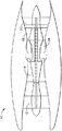
図1は、低圧圧縮機12、高圧圧縮機14、及び燃焼器16を含むガスタービンエンジン10の概略図である。エンジン10はまた、高圧タービン18及び低圧タービン20を含む。
FIG. 1 is a schematic diagram of a
運転中、空気が低圧圧縮機12を通って流れ、加圧された空気は、低圧圧縮機12から高圧圧縮機14に供給される。高度に加圧された空気は、燃焼器16に送り込まれる。燃焼器16からの空気流(図1には示さず)は、タービン18及び20を駆動する。1つの実施形態において、ガスタービンエンジン10は、CFM internationalから入手可能なCFM型エンジンである。別の実施形態において、ガスタービンエンジン10は、オハイオ州シンシナチ所在のGeneral Electric Companyから入手可能なLM6000 DLE型エンジンである。
During operation, air flows through the
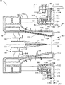
図2は、図1に示すエンジン10と同様の、ガスタービンエンジンに用いるための燃焼器16の断面図であり、図3は、区域3に沿った燃焼器16の部分拡大図である。燃焼器16は、環状の半径方向外側ライナ32及び半径方向内側ライナ34により形成された燃焼域すなわち燃焼室30を含む。より具体的には、外側ライナ32は燃焼室30の外側境界面を形成し、また内側ライナ34は燃焼室30の内側境界面を形成する。ライナ32及び34は、該ライナ32及び34の周りを周方向に延びる環状の燃焼器ケーシング36の半径方向内側に位置する。
FIG. 2 is a cross-sectional view of a
燃焼器16はまた、それぞれ外側ライナ32及び内側ライナ34の上流に取り付けられた複数の環状ドーム40を含む。ドーム40は燃焼室30の上流端を形成し、またミキサ組立体41が、ドーム40の周りに周方向に間隔を置いて配置されて、燃料及び空気の混合気を燃焼室30に供給する。燃焼器16が2つの環状ドーム40を含むので、この燃焼器16は、二重式環状燃焼器(DAC)として知られている。これに代えて、燃焼器16は、単式環状燃焼器(SAC)又は三重式環状燃焼器とすることもできる。
The
各ミキサ組立体41は、パイロットミキサ42と、主ミキサ44と、それらの間に延びる環状のセンタボデー43とを含む。センタボデー43は、パイロットミキサ42と流れ連通しかつ該パイロットミキサ42の下流に位置するチャンバ50を形成する。チャンバ50は、対称軸線52を有しており、ほぼ円筒形の形状である。パイロットセンタボデー54は、チャンバ50内に延び、対称軸線52に対して対称的に取り付けられる。1つの実施形態において、センタボデー54は、燃料の液滴をパイロットチャンバ50内に供給するための燃料インジェクタ58を含む。
Each
パイロットミキサ42はまた、1対の同心に取り付けられたスワーラ60を含む。より具体的には、例示的な実施形態において、スワーラ60は、アキシャルスワーラであり、一体に形成されたパイロット内側スワーラ62とパイロット外側スワーラ64とを含む。別の形態では、内側スワーラ62及び外側スワーラ64は、個別の部品である。パイロット内側スワーラ62は環状であり、センタボデー54の周りに周方向に配置される。パイロット外側スワーラ64は、パイロット内側スワーラ62とセンタボデー43の半径方向内側表面78との間に周方向に配置される。各スワーラ62及び64は、複数のベーン(図示せず)を含む。ガス燃料噴射口(図示せず)が、パイロット外側スワーラベーン64の後縁近傍でパイロット外側スワーラベーン64に隣接して延びる表面103内に設置される。スワーラ62及び64、並びに噴射口の位置は、エンジンの低出力運転時に、所望の点火特性、リーン安定性、かつ低い一酸化炭素(CO)及び炭化水素(HC)エミッションが得られるように選択される。1つの実施形態において、パイロットスプリッタ(図示せず)が、半径方向にパイロット内側スワーラ62とパイロット外側スワーラ64との間に配置され、パイロット内側スワーラ62及びパイロット外側スワーラ64から下流に延びる。
1つの実施形態において、パイロットスワーラ62は、それを通って流れる空気を、パイロットスワーラ64を通って流れる空気と同じ方向に旋回させる。別の実施形態において、パイロット内側スワーラ62は、それを通って流れる空気を、パイロット外側スワーラ64がそれを通って流れる空気を旋回させる第2の方向と反対方向の第1の方向に旋回させる。
In one embodiment,
主ミキサ44は、センタボデー43の半径方向外側表面100と組み合わさって環状のプレミキサキャビティ82を形成する外側スロート表面81を含む。主ミキサ44は、パイロットミキサ42に対して同心に位置合わせされ、パイロットミキサ42の周りを周方向に延びる。
The
ドームプレート80は、該ドームプレート80を貫通する複数の開口部86を含む。1つの実施形態において、開口部86は、対称軸線52の周りでほぼ周方向に延びる一連の穴である。別の実施形態において、開口部86は、対称軸線52の周りでほぼ周方向に延びる一連の溝つきスロットである。
The
例示的な実施形態において、環状センタボデー43は、該センタボデーの半径方向外側表面100に設置された複数の噴射ポート98を含み、該噴射ポートは、センタボデー43から半径方向外向きに主ミキサキャビティ82中に燃料を噴射する。燃料噴射ポート98は、主ミキサ44内の周方向の燃料・空気の混合を促進する。例示的な実施形態において、センタボデー43は、複数列の周方向に間隔を置いて配置された噴射ポート98を含む。別の実施形態において、センタボデー43は、周方向に間隔を置いて配置された列には配列されていない複数の噴射ポート98を含む。更に別の実施形態においては、環状センタボデー43は、燃料噴射ポート98を含まない。噴射ポート98の位置は、燃料・空気の混合の度合を調整して、変化するエンジン運転状態のもとで低い窒素酸化物(NOx)エミッションを達成し、また完全燃焼を保証するように選択される。更に、噴射ポートの位置はまた、燃焼の不安定性を減少又は防止するのを促進するように選択される。
In the exemplary embodiment, the
センタボデー43は、パイロットミキサ42と主ミキサ44とを分離する。従って、パイロットミキサ42は、パイロットによる運転時に主ミキサ44から覆い隠されて、パイロットの性能の安定性及び効率を向上させると同時に、CO及びHCエミッションを減少させることを可能にする。更に、センタボデー43は、燃焼器16中に噴射されたパイロット燃料を完全に燃焼終了させるのを促進するような形状にされる。より具体的には、センタボデー43の内側通路壁102は、入口部分103と、収束表面104と、後部シールド106とを含む。
The
表面104は、入口部分103から後部シールド106まで延び、パイロットミキサ42内にベンチュリスロート107を形成する。後部シールド106は、表面104と、センタボデー43の半径方向外側壁110の下流に形成された環状リップ108との間を延びる。別の実施形態において、センタボデー43はリップ108を含まない。例示的な実施形態において、リップ108は、壁110と該リップ108との間にキャビティ114が形成されるように、後部シールド106から半径方向外向きに延びる。
The
スワーラ140は、ラジアル流入サイクロンスワーラであり、該スワーラからの流体の流れは、対称軸線52に向けて半径方向内向きに吐出される。別の実施形態において、スワーラ140は、コニカルスワーラである。より具体的には、例示的な実施形態において、スワーラ140は、燃料源(図示せず)に流れ連通した状態で結合され、従って、該スワーラから燃料を噴射するように構成され、そのことが、スワーラ140から半径方向内向きにまた噴射ポート98から半径方向外向きに噴射される燃料の燃料・空気の混合を向上させるのを促進する。別の実施形態において、第1のスワーラ140は、同一方向に回転又は反対方向に回転することができる旋回翼(図示せず)の複数の対に分割される。
The
スワーラ140は、フェルール組立体154を介してドームプレート80の上流側145に当接して結合される。熱シールド180は、保持ナット146によりドームプレート80に結合される。保持ナット146、スペーサ160、ドームプレート80、及び熱シールド180は、スワーラ140の上流からキャビティ82まで延びる少なくとも1つの通路150を形成する。1つの実施形態において、通路150は、対称軸線52の周りでほぼ周方向に延びる一連の穴である。別の実施形態において、通路150は、対称軸線52の周りでほぼ周方向に延びる一連のスロットである。例示的な実施形態において、スワーラの通路150は、該通路150から吐出される流体が下流方向かつ半径方向内向きに向けられるように、対称軸線52に対して斜めに配置される。
The
部分144内においてプレミキサキャビティ82の半径方向外側に配置されたフェルール組立体154は、上流の空気をスワーラキャビティ82からシールすることを可能にする。従って、フェルール組立体154は、キャビティ82内に流入する空気の量を制御することを可能にする。
A
環状のスペーサ160が、スワーラ140に結合され、かつ該スワーラ140から下流に延びる。より具体的には、例示的な実施形態において、スペーサ160は、ほぼL形の形状であり、スワーラ140に当接して結合された半径方向内側部分162とドームプレート80の下流側166に当接して結合された半径方向外側部分164とを含み、環状の空隙170がドームプレート80とスペーサ160とにより形成されかつ境界付けられるようになる。
An
スワーラの通路150は、該通路150を通って流れる流体が空隙170内に吐出されるように、該空隙170と流れ連通している。流体はその後、空隙170からスペーサ160内に形成された開口部174を通って吐出される。より具体的には、スペーサの開口部174は、スペーサ160の半径方向外側176から該スペーサ160の半径方向内側178まで延びる。1つの実施形態において、開口部174は、対称軸線52の周りでほぼ周方向に延びる一連の穴である。別の実施形態において、開口部174は、対称軸線52の周りでほぼ周方向に延びる一連のスロットである。例示的な実施形態において、スペーサ開口部174は、該開口部174から吐出される流体が下流方向かつ半径方向内向きに向けられるように、対称軸線52に対して斜めに配置される。
The
熱シールド180は、スワーラ140に結合され、軸方向部分182と該軸方向部分182からほぼ垂直にかつ半径方向外向きに延びる半径方向部分184とを含む。より具体的には、軸方向部分182は、上流端186から半径方向部分184まで延び、半径方向部分184は、軸方向部分182から下流端188まで延びる。1つの実施形態において、熱シールドの軸方向部分182は、それに限定するのではないが、該軸方向部分182内に形成されたボス190とスペーサ部分162とを貫通してスワーラの下流部分144内に延びるねじ付き締結具(図示せず)のような機械的手段によりスワーラ140に結合される。別の実施形態において、熱シールドの軸方向部分182は、ろう付けのような非機械的手段によりスワーラ140に結合される。ボス190は、熱シールド180がスワーラ140に結合されるとスペーサ160と熱シールドの軸方向部分182との間に空隙192が形成されるように、該熱シールドの軸方向部分182から外向きに延びる。
The heat shield 180 is coupled to the
熱シールドの軸方向部分182は、それを貫通する少なくとも1つの開口部194を含む。具体的には、開口部194は、空隙192とプレミキサキャビティ82との間を延びる。より具体的には、開口部194は、該開口部194から吐出される流体が該開口部を通って加速され、対称軸線52にほぼ垂直でかつスワーラ140からキャビティ82中に吐出される流体の方向にほぼ平行な方向に、プレミキサキャビティ82中に半径方向内向きに吐出されるように配向される。
The axial portion 182 of the heat shield includes at least one
熱シールドの半径方向部分184は、下流端188でドームプレートの下流側166に結合される。より具体的には、下流端188は、半径方向部分184からほぼ垂直に延びる。従って、半径方向部分184がドームプレートの下流側166に結合されると、半径方向部分184の上流側表面200は、ドームプレートの下流側166から距離202に位置する。
The
燃料供給システムが、燃料を燃焼器16に供給するようになっており、パイロット燃料回路及び主燃料回路を含む。パイロット燃料回路は、パイロットミキサ42に燃料を供給し、主燃料回路は、主ミキサ44に燃料を供給し、かつ燃焼器16内で発生する窒素酸化物エミッションを制御するために用いられる複数の独立した燃料段を含む。
A fuel supply system is adapted to supply fuel to the
運転において、ガスタービンエンジン10が始動してアイドリング運転状態で運転されると、燃料及び空気が燃焼器16に供給される。ガスタービンのアイドリング運転状態では、燃焼器16は、パイロットミキサ42のみを使用して作動する。パイロット燃料回路が、パイロット燃料インジェクタ58を通して、又はパイロット外側スワーラベーン64を通して燃焼器16に燃料を噴射する。同時に、空気流は、パイロットスワーラ60及び主ミキサスワーラ140に流入する。より具体的には、空気流は、パイロットミキサ42の下流のパイロット火炎域内に向けられる。パイロットミキサ42は、燃焼器の全燃料・空気混合比が所定のリーン可燃限界を下回る場合、ほぼ理論空燃比又は燃料リッチ状態で作動可能である。より具体的には、パイロット火炎は、ベンチュリスロート107に隣接してかつ該ベンチュリスロート107の下流に集中する状態になり、環状センタボデー43により主ミキサ44を通して吐出される主空気流から覆い隠される。
In operation, when the
エンジン10がアイドリング運転から部分出力運転に出力を増大されると、パイロットミキサ42への燃料流が増加され、燃料リッチのパイロット火炎を生じさせる。この運転モード中は、パイロット火炎による生成物は、主ミキサスワーラ140を通して吐出される空気流と混合し、燃焼室30を出る前に更に酸化される。
When the
パイロットのみの部分出力モードから、燃料流がパイロットミキサ42及び主ミキサ44に供給される高出力運転モードへの移行は、燃料流量がミキサ42及び44の両方における完全燃焼を支えるのに十分である場合に生じる。より具体的には、ガスタービンエンジン10がアイドリング運転状態から増大出力運転状態に加速されると、追加の燃料及び空気が燃焼器16内に導入される。増大出力運転状態では、パイロット燃料段に加えて、主ミキサ44には、スワーラ140を通して半径方向内向きに及び/又は燃料噴射ポート98から半径方向外向きに噴射された燃料が供給される。主ミキサスワーラ140は、半径方向及び周方向の燃料・空気の混合を促進して、燃焼のためのほぼ均一な燃料及び空気の分配をもたらす。燃料・空気混合気を均一に分配することは、完全燃焼を達成して高出力運転時のNOxエミッションを減少させるのを促進する。
The transition from the pilot only partial power mode to the high power mode of operation where fuel flow is supplied to the
更に、運転中、空気流は、ドームプレートの開口部86を通りかつスワーラの通路150を通って下流に向けられる。スワーラの通路150から吐出された空気流はその後、熱シールド180のインピンジメント冷却のためにスペーサの開口部174を通して導かれる。より具体的には、通路150、開口部86及び開口部174から吐出された空気流は、熱シールドの上流側表面200にインピンジメント冷却を施す。
Further, during operation, the air flow is directed downstream through the dome plate opening 86 and through the
熱シールドの上流側表面200に衝突した後、使用済み冷却用流体はその後空隙192を通して導かれ、熱シールドの開口部194からプレミキサキャビティ82内に半径方向内向きに向けられる。より具体的には、インピンジメント冷却に用いられた冷却用流体は、ドームプレート80を通して加速されて熱シールドの表面200に衝突した後、全圧における純損失を生じる。使用済み流体はその後、熱シールドの開口部194を通して加速され、プレミキサキャビティ82内に導入される。スワーラ140を通ってプレミキサキャビティ82内に流入する空気の全圧は、空気が上流のほぼ停滞した状態からスワーラ140を通りプレミキサキャビティ82へと流れるにつれて減少する。従って、熱シールドの開口部194を通ってキャビティ82に入る使用済み冷却用流体の圧力は、スワーラ140を通ってキャビティ82内に流入する空気の圧力よりも高く、またキャビティ82内の空気・燃料混合気の局所静圧をも超える。生成された圧力差は、使用済み冷却用流体と、スワーラ140を通ってキャビティ82に流入する空気と、キャビティ82内の空気・燃料混合気との効率的な混合を促進する。より具体的には、混合気がキャビティ82を出る前に、圧力差により、使用済み冷却用流体の空気・燃料混合気との完全な混合が促進される。更に、開口部150、86、174、及び194の大きさ、配向、及び数は、そのような混合を高めるのを促進するように可変的に選択される。
After impinging on the
上記の燃焼器は、費用効果が良くかつ高い信頼性がある。燃焼器は、ドームプレートに結合されたスワーラ及び熱シールドを備えるミキサ組立体を含む。ドームプレート及びスワーラは、熱シールドのインピンジメント冷却のために冷却用流体を下流に導く冷却開口部を含む。使用済み冷却用流体はその後、プレミキサキャビティ内の空気・燃料混合気の局所静圧を越える圧力でプレミキサキャビティ内に導入される。従って、混合気がプレミキサキャビティから吐出される前に、圧力差により、使用済み冷却用流体と空気・燃料混合気との混合の向上が促進される。その結果、燃焼器は、高い燃焼効率でかつ低い一酸化炭素、窒素酸化物、及び排煙エミッションで作動する。 The combustor described above is cost effective and highly reliable. The combustor includes a mixer assembly that includes a swirler and a heat shield coupled to a dome plate. The dome plate and swirler include a cooling opening that directs cooling fluid downstream for impingement cooling of the heat shield. The spent cooling fluid is then introduced into the premixer cavity at a pressure that exceeds the local static pressure of the air / fuel mixture in the premixer cavity. Therefore, before the air-fuel mixture is discharged from the premixer cavity, the improvement in the mixing of the used cooling fluid and the air / fuel mixture is promoted by the pressure difference. As a result, the combustor operates with high combustion efficiency and low carbon monoxide, nitrogen oxides, and flue gas emissions.
燃焼器組立体の例示的な実施形態を上に詳細に説明している。このシステムは、本明細書に説明する特定の実施形態に限定されるものではなく、むしろ、各組立体の部品は、本明細書に説明する他の部品から独立してかつ個別に利用することができる。燃焼器組立体の各部品は、他の燃焼器組立体の部品と組み合わせて用いることも可能である。 Exemplary embodiments of combustor assemblies are described in detail above. This system is not limited to the specific embodiments described herein, but rather the components of each assembly are utilized independently and separately from the other components described herein. Can do. Each component of the combustor assembly can be used in combination with other combustor assembly components.
本発明を種々の特定の実施形態に関して説明してきたが、本発明は特許請求の範囲の技術思想及び技術的範囲内の変更形態で実施可能であることは、当業者には理解されるであろう。なお、特許請求の範囲に記載された符号は、理解容易のためであってなんら発明の技術的範囲を実施例に限縮するものではない。 While the invention has been described in terms of various specific embodiments, those skilled in the art will recognize that the invention can be practiced with modification within the spirit and scope of the claims. Let's go. In addition, the code | symbol described in the claim is for easy understanding, and does not limit the technical scope of an invention to an Example at all.
10 ガスタービンエンジン
16 燃焼器
30 燃焼室
32 外側ライナ
34 内側ライナ
36 燃焼器ケーシング
40 ドーム
41 ミキサ組立体
42 パイロットミキ
43 センタボデー
44 主ミキサ
50 チャンバ
DESCRIPTION OF
Claims (10)
流体を通して燃焼室(30)に流すパイロットミキサ(42)と、
前記パイロットミキサ(42)に対して同心に位置合わせされると共に該パイロットミキサ(42)の周りを周方向に延び、流体を通して燃焼室(30)に流す主ミキサ(44)と、
流体の流れを通過させて前記主ミキサ(44)内に導くエアスワーラ(140)と、
前記エアスワーラから下流に延びるドームプレート(80)と、
前記エアスワーラ及び前記ドームプレートの少なくとも1つから下流に延びる熱シールド(180)と、
を含み、
前記熱シールドは、下流側(188)及び上流側(186)を含み、前記熱シールド(180)は、前記主ミキサ(44)の少なくとも一部を形成し、
前記主ミキサ(44)及び前記ドームプレートの少なくとも1つは、前記熱シールドの少なくとも一部にインピンジメント冷却を施すための冷却用流体を受けるように構成された少なくとも1つの冷却開口部(150)を含み、
前記熱シールドは、前記下流側(188)と上流側(186)との間に、前記インピンジメント冷却に使われた冷却流体を前記主ミキサ(44)に吐出する開口部(194)を含む
ことを特徴とするミキサ組立体(41)。 A mixer assembly (41) for a gas turbine engine combustor (16) comprising:
A pilot mixer (42) flowing through the fluid to the combustion chamber (30);
A main mixer (44) that is concentrically aligned with the pilot mixer (42) and extends circumferentially around the pilot mixer (42) and flows through the fluid to the combustion chamber (30);
An air swirler (140) for passing a flow of fluid into the main mixer (44) ;
A dome plate (80) extending downstream from the air swirler;
A heat shield (180) extending downstream from at least one of the air swirler and the dome plate;
Including
The heat shield includes a downstream side (188) and an upstream side (186), the heat shield (180) forming at least a portion of the main mixer (44) ;
At least one of the main mixer (44) and the dome plate is at least one cooling opening (150) configured to receive a cooling fluid for providing impingement cooling to at least a portion of the heat shield. Including
The heat shield includes an opening (194) between the downstream side (188) and the upstream side (186 ) for discharging the cooling fluid used for impingement cooling to the main mixer (44). A mixer assembly (41) characterized by:
前記センタボデーは、パイロットミキサの下流に対称軸線(52)を有するパイロットチャンバ(50)を形成し、
前記熱シールドの前記少なくとも1つの開口部(194)は、前記対称軸線(52)に垂直に該開口部(194)から流体を吐出するように構成されていることを特徴とする、請求項1又は2に記載のミキサ組立体(41)。 An annular centerbody (43) extending between the main mixer (44) and the pilot mixer (42);
The centerbody forms a pilot chamber (50) having an axis of symmetry (52) downstream of the pilot mixer;
The at least one opening (194) of the heat shield is configured to discharge fluid from the opening (194) perpendicular to the axis of symmetry (52). Or the mixer assembly (41) of claim 2;
前記ミキサ組立体は、流体を通して燃焼室(30)に流すパイロットミキサ(42)と、該パイロットミキサ(42)に対して同心に位置合わせされると共に該パイロットミキサ(42)の周りを周方向に延び、流体を通して燃焼室(30)に流す主ミキサ(44)と、ドームプレート(40)と、熱シールド(180)とを含み、
前記主ミキサ(44)は、流体の流れを通過させて該主ミキサ(44)内に導くためのエアスワーラ(140)を含み、
前記ドームプレートは、前記エアスワーラから下流に延びており、
前記熱シールドは、前記エアスワーラ及び前記ドームプレートの少なくとも1つから下流に延びて前記主ミキサ(44)の少なくとも一部を形成し、かつ下流側(188)及び上流側(186)を含み、
前記下流側は、前記燃焼室と前記上流側との間に位置し、
前記主ミキサ(44)及び前記ドームプレートの少なくとも1つは、それを貫通して、前記熱シールドの少なくとも一部にインピンジメント冷却を施すための冷却用流体を吐出する少なくとも1つの開口部(150)を含み、
前記熱シールドは、前記下流側(188)と上流側(186)との間に、前記インピンジメント冷却に使われた冷却流体を前記主ミキサ(44)に吐出する開口部(194)を含むことを特徴とするガスタービンエンジン燃焼器(16)。 A gas turbine engine combustor (16) comprising a mixer assembly (41) and a combustion chamber (30), comprising:
The mixer assembly includes a pilot mixer (42) that flows through the fluid to the combustion chamber (30) and is concentrically aligned with the pilot mixer (42) and circumferentially about the pilot mixer (42). A main mixer (44) extending and flowing through the fluid to the combustion chamber (30), a dome plate (40), and a heat shield (180);
The main mixer (44) comprises a Easuwara (140) for guiding the by pass fluid flow the main mixer (44),
The dome plate extends downstream from the air swirler;
The heat shield extends downstream from at least one of the air swirler and the dome plate to form at least a portion of the main mixer (44) and includes a downstream side (188) and an upstream side (186);
The downstream side is located between the combustion chamber and the upstream side,
At least one of the main mixer (44) and the dome plate passes therethrough and discharges a cooling fluid for impingement cooling to at least a portion of the heat shield (150). )
The heat shield includes an opening (194) between the downstream side (188) and the upstream side (186 ) for discharging the cooling fluid used for impingement cooling to the main mixer (44). A gas turbine engine combustor (16) characterized by:
前記センタボデーは、パイロットミキサの下流に対称軸線(52)を有するパイロットチャンバ(50)を形成し、
前記熱シールドの前記少なくとも1つの開口部(194)は、前記対称軸線(52)に垂直に該開口部(194)から流体を吐出するように構成されていることを特徴とする、請求項6乃至8のいずれか1項に記載のガスタービンエンジン燃焼器(16)。 An annular centerbody (43) extending between the main mixer (44) and the pilot mixer;
The centerbody forms a pilot chamber (50) having an axis of symmetry (52) downstream of the pilot mixer;
The at least one opening (194) of the heat shield is configured to discharge fluid from the opening (194) perpendicular to the axis of symmetry (52). A gas turbine engine combustor (16) according to any one of claims 1 to 8.
Applications Claiming Priority (1)
| Application Number | Priority Date | Filing Date | Title |
|---|---|---|---|
| US10/308,711 US6871501B2 (en) | 2002-12-03 | 2002-12-03 | Method and apparatus to decrease gas turbine engine combustor emissions |
Publications (3)
| Publication Number | Publication Date |
|---|---|
| JP2004184072A JP2004184072A (en) | 2004-07-02 |
| JP2004184072A5 JP2004184072A5 (en) | 2007-01-25 |
| JP4658471B2 true JP4658471B2 (en) | 2011-03-23 |
Family
ID=32325858
Family Applications (1)
| Application Number | Title | Priority Date | Filing Date |
|---|---|---|---|
| JP2003401025A Expired - Fee Related JP4658471B2 (en) | 2002-12-03 | 2003-12-01 | Method and apparatus for reducing combustor emissions in a gas turbine engine |
Country Status (4)
| Country | Link |
|---|---|
| US (1) | US6871501B2 (en) |
| EP (1) | EP1429078B1 (en) |
| JP (1) | JP4658471B2 (en) |
| CA (1) | CA2451318C (en) |
Families Citing this family (47)
| Publication number | Priority date | Publication date | Assignee | Title |
|---|---|---|---|---|
| US7080515B2 (en) * | 2002-12-23 | 2006-07-25 | Siemens Westinghouse Power Corporation | Gas turbine can annular combustor |
| US20050229600A1 (en) * | 2004-04-16 | 2005-10-20 | Kastrup David A | Methods and apparatus for fabricating gas turbine engine combustors |
| US7340900B2 (en) * | 2004-12-15 | 2008-03-11 | General Electric Company | Method and apparatus for decreasing combustor acoustics |
| US7596949B2 (en) * | 2006-02-23 | 2009-10-06 | General Electric Company | Method and apparatus for heat shielding gas turbine engines |
| FR2899314B1 (en) * | 2006-03-30 | 2008-05-09 | Snecma Sa | DEVICE FOR INJECTING A MIXTURE OF AIR AND FUEL, COMBUSTION CHAMBER AND TURBOMACHINE HAVING SUCH A DEVICE |
| US8596071B2 (en) * | 2006-05-05 | 2013-12-03 | General Electric Company | Method and apparatus for assembling a gas turbine engine |
| FR2903172B1 (en) * | 2006-06-29 | 2008-10-17 | Snecma Sa | ARRANGEMENT FOR A TURBOMACHINE COMBUSTION CHAMBER HAVING A FLANGE FAULT |
| US7926279B2 (en) * | 2006-09-21 | 2011-04-19 | Siemens Energy, Inc. | Extended life fuel nozzle |
| US7975487B2 (en) * | 2006-09-21 | 2011-07-12 | Solar Turbines Inc. | Combustor assembly for gas turbine engine |
| US20080083224A1 (en) * | 2006-10-05 | 2008-04-10 | Balachandar Varatharajan | Method and apparatus for reducing gas turbine engine emissions |
| US8099960B2 (en) * | 2006-11-17 | 2012-01-24 | General Electric Company | Triple counter rotating swirler and method of use |
| US20080163627A1 (en) * | 2007-01-10 | 2008-07-10 | Ahmed Mostafa Elkady | Fuel-flexible triple-counter-rotating swirler and method of use |
| US7905093B2 (en) * | 2007-03-22 | 2011-03-15 | General Electric Company | Apparatus to facilitate decreasing combustor acoustics |
| US8205457B2 (en) | 2007-12-27 | 2012-06-26 | General Electric Company | Gas turbine engine combustor and method for delivering purge gas into a combustion chamber of the combustor |
| US9188341B2 (en) * | 2008-04-11 | 2015-11-17 | General Electric Company | Fuel nozzle |
| US8281597B2 (en) * | 2008-12-31 | 2012-10-09 | General Electric Company | Cooled flameholder swirl cup |
| US8256226B2 (en) * | 2009-04-23 | 2012-09-04 | General Electric Company | Radial lean direct injection burner |
| US9267443B2 (en) | 2009-05-08 | 2016-02-23 | Gas Turbine Efficiency Sweden Ab | Automated tuning of gas turbine combustion systems |
| US9354618B2 (en) | 2009-05-08 | 2016-05-31 | Gas Turbine Efficiency Sweden Ab | Automated tuning of multiple fuel gas turbine combustion systems |
| US9671797B2 (en) | 2009-05-08 | 2017-06-06 | Gas Turbine Efficiency Sweden Ab | Optimization of gas turbine combustion systems low load performance on simple cycle and heat recovery steam generator applications |
| US8437941B2 (en) | 2009-05-08 | 2013-05-07 | Gas Turbine Efficiency Sweden Ab | Automated tuning of gas turbine combustion systems |
| US8468831B2 (en) * | 2009-07-13 | 2013-06-25 | General Electric Company | Lean direct injection for premixed pilot application |
| DE102009046066A1 (en) * | 2009-10-28 | 2011-05-12 | Man Diesel & Turbo Se | Burner for a turbine and thus equipped gas turbine |
| US20110162375A1 (en) * | 2010-01-05 | 2011-07-07 | General Electric Company | Secondary Combustion Fuel Supply Systems |
| US20110162379A1 (en) * | 2010-01-06 | 2011-07-07 | General Electric Company | Apparatus and method for supplying fuel |
| US8943835B2 (en) | 2010-05-10 | 2015-02-03 | General Electric Company | Gas turbine engine combustor with CMC heat shield and methods therefor |
| US9074530B2 (en) * | 2011-01-13 | 2015-07-07 | General Electric Company | Stoichiometric exhaust gas recirculation and related combustion control |
| US9920932B2 (en) | 2011-01-26 | 2018-03-20 | United Technologies Corporation | Mixer assembly for a gas turbine engine |
| US8973368B2 (en) * | 2011-01-26 | 2015-03-10 | United Technologies Corporation | Mixer assembly for a gas turbine engine |
| US8893500B2 (en) | 2011-05-18 | 2014-11-25 | Solar Turbines Inc. | Lean direct fuel injector |
| US8919132B2 (en) | 2011-05-18 | 2014-12-30 | Solar Turbines Inc. | Method of operating a gas turbine engine |
| US9222674B2 (en) | 2011-07-21 | 2015-12-29 | United Technologies Corporation | Multi-stage amplification vortex mixture for gas turbine engine combustor |
| US9182124B2 (en) | 2011-12-15 | 2015-11-10 | Solar Turbines Incorporated | Gas turbine and fuel injector for the same |
| US9115896B2 (en) | 2012-07-31 | 2015-08-25 | General Electric Company | Fuel-air mixer for use with a combustor assembly |
| US9322415B2 (en) | 2012-10-29 | 2016-04-26 | United Technologies Corporation | Blast shield for high pressure compressor |
| WO2015026760A1 (en) * | 2013-08-20 | 2015-02-26 | United Technologies Corporation | Dual fuel nozzle system and apparatus |
| US9528704B2 (en) | 2014-02-21 | 2016-12-27 | General Electric Company | Combustor cap having non-round outlets for mixing tubes |
| US9528702B2 (en) * | 2014-02-21 | 2016-12-27 | General Electric Company | System having a combustor cap |
| EP3299720B1 (en) * | 2016-09-22 | 2020-11-04 | Ansaldo Energia IP UK Limited | Combustor front assembly for a gas turbine |
| US10738704B2 (en) | 2016-10-03 | 2020-08-11 | Raytheon Technologies Corporation | Pilot/main fuel shifting in an axial staged combustor for a gas turbine engine |
| US10724740B2 (en) * | 2016-11-04 | 2020-07-28 | General Electric Company | Fuel nozzle assembly with impingement purge |
| US10634353B2 (en) * | 2017-01-12 | 2020-04-28 | General Electric Company | Fuel nozzle assembly with micro channel cooling |
| EP3775694B1 (en) * | 2018-04-06 | 2022-01-12 | General Electric Company | Premixer for low emissions gas turbine combustor |
| US10816507B2 (en) | 2019-03-20 | 2020-10-27 | Raytheon Technologies Corporation | Apparatus and method and system for inspecting a component of a gas turbine engine |
| US11859819B2 (en) | 2021-10-15 | 2024-01-02 | General Electric Company | Ceramic composite combustor dome and liners |
| US20230220802A1 (en) * | 2022-01-13 | 2023-07-13 | General Electric Company | Combustor with lean openings |
| CN115507389B (en) * | 2022-09-02 | 2024-03-19 | 哈尔滨工程大学 | Low-pollution tower type coaxial grading cyclone for liquid fuel ship |
Citations (6)
| Publication number | Priority date | Publication date | Assignee | Title |
|---|---|---|---|---|
| JPH1068524A (en) * | 1996-07-25 | 1998-03-10 | Soc Natl Etud Constr Mot Aviat <Snecma> | Bowl deflector assembly for combustion chamber of turbine engine |
| JPH10185193A (en) * | 1996-09-26 | 1998-07-14 | Soc Natl Etud Constr Mot Aviat <Snecma> | Pneumatic injection system for fuel mixed gas |
| US5956955A (en) * | 1994-08-01 | 1999-09-28 | Bmw Rolls-Royce Gmbh | Heat shield for a gas turbine combustion chamber |
| JP2002139221A (en) * | 2000-09-08 | 2002-05-17 | General Electric Co <Ge> | Fuel nozzle assembly for reduced engine exhaust emission |
| US20020162333A1 (en) * | 2001-05-02 | 2002-11-07 | Honeywell International, Inc., Law Dept. Ab2 | Partial premix dual circuit fuel injector |
| JP2002340338A (en) * | 2001-04-27 | 2002-11-27 | General Electric Co <Ge> | Operating methods of combustor, gas turbine engine and engine |
Family Cites Families (23)
| Publication number | Priority date | Publication date | Assignee | Title |
|---|---|---|---|---|
| US4567857A (en) | 1980-02-26 | 1986-02-04 | The United States Of America As Represented By The Administrator Of The National Aeronautics And Space Administration | Combustion engine system |
| FR2596102B1 (en) * | 1986-03-20 | 1988-05-27 | Snecma | INJECTION DEVICE WITH AXIAL CENTRIPE |
| GB9018014D0 (en) * | 1990-08-16 | 1990-10-03 | Rolls Royce Plc | Gas turbine engine combustor |
| US5323604A (en) | 1992-11-16 | 1994-06-28 | General Electric Company | Triple annular combustor for gas turbine engine |
| US5444982A (en) * | 1994-01-12 | 1995-08-29 | General Electric Company | Cyclonic prechamber with a centerbody |
| US5584178A (en) | 1994-06-14 | 1996-12-17 | Southwest Research Institute | Exhaust gas combustor |
| US5613363A (en) | 1994-09-26 | 1997-03-25 | General Electric Company | Air fuel mixer for gas turbine combustor |
| US5590529A (en) | 1994-09-26 | 1997-01-07 | General Electric Company | Air fuel mixer for gas turbine combustor |
| US5943866A (en) * | 1994-10-03 | 1999-08-31 | General Electric Company | Dynamically uncoupled low NOx combustor having multiple premixers with axial staging |
| DE4444961A1 (en) * | 1994-12-16 | 1996-06-20 | Mtu Muenchen Gmbh | Device for cooling in particular the rear wall of the flame tube of a combustion chamber for gas turbine engines |
| US5623827A (en) * | 1995-01-26 | 1997-04-29 | General Electric Company | Regenerative cooled dome assembly for a gas turbine engine combustor |
| DE19508111A1 (en) * | 1995-03-08 | 1996-09-12 | Bmw Rolls Royce Gmbh | Heat shield arrangement for a gas turbine combustor |
| GB2299399A (en) * | 1995-03-25 | 1996-10-02 | Rolls Royce Plc | Variable geometry air-fuel injector |
| US5822992A (en) | 1995-10-19 | 1998-10-20 | General Electric Company | Low emissions combustor premixer |
| US6047550A (en) | 1996-05-02 | 2000-04-11 | General Electric Co. | Premixing dry low NOx emissions combustor with lean direct injection of gas fuel |
| AU7357298A (en) | 1997-03-26 | 1998-10-20 | San Diego State University Foundation | Fuel/air mixing device for jet engines |
| US6141967A (en) | 1998-01-09 | 2000-11-07 | General Electric Company | Air fuel mixer for gas turbine combustor |
| US6530223B1 (en) * | 1998-10-09 | 2003-03-11 | General Electric Company | Multi-stage radial axial gas turbine engine combustor |
| US6195607B1 (en) | 1999-07-06 | 2001-02-27 | General Electric Company | Method and apparatus for optimizing NOx emissions in a gas turbine |
| EP1070914B1 (en) * | 1999-07-22 | 2003-12-03 | ALSTOM (Switzerland) Ltd | Premix burner |
| US6298667B1 (en) * | 2000-06-22 | 2001-10-09 | General Electric Company | Modular combustor dome |
| US6474071B1 (en) * | 2000-09-29 | 2002-11-05 | General Electric Company | Multiple injector combustor |
| US6418726B1 (en) | 2001-05-31 | 2002-07-16 | General Electric Company | Method and apparatus for controlling combustor emissions |
-
2002
- 2002-12-03 US US10/308,711 patent/US6871501B2/en not_active Expired - Lifetime
-
2003
- 2003-11-27 CA CA2451318A patent/CA2451318C/en not_active Expired - Fee Related
- 2003-12-01 JP JP2003401025A patent/JP4658471B2/en not_active Expired - Fee Related
- 2003-12-02 EP EP03257581.3A patent/EP1429078B1/en not_active Expired - Lifetime
Patent Citations (6)
| Publication number | Priority date | Publication date | Assignee | Title |
|---|---|---|---|---|
| US5956955A (en) * | 1994-08-01 | 1999-09-28 | Bmw Rolls-Royce Gmbh | Heat shield for a gas turbine combustion chamber |
| JPH1068524A (en) * | 1996-07-25 | 1998-03-10 | Soc Natl Etud Constr Mot Aviat <Snecma> | Bowl deflector assembly for combustion chamber of turbine engine |
| JPH10185193A (en) * | 1996-09-26 | 1998-07-14 | Soc Natl Etud Constr Mot Aviat <Snecma> | Pneumatic injection system for fuel mixed gas |
| JP2002139221A (en) * | 2000-09-08 | 2002-05-17 | General Electric Co <Ge> | Fuel nozzle assembly for reduced engine exhaust emission |
| JP2002340338A (en) * | 2001-04-27 | 2002-11-27 | General Electric Co <Ge> | Operating methods of combustor, gas turbine engine and engine |
| US20020162333A1 (en) * | 2001-05-02 | 2002-11-07 | Honeywell International, Inc., Law Dept. Ab2 | Partial premix dual circuit fuel injector |
Also Published As
| Publication number | Publication date |
|---|---|
| US6871501B2 (en) | 2005-03-29 |
| EP1429078A1 (en) | 2004-06-16 |
| US20040103668A1 (en) | 2004-06-03 |
| CA2451318A1 (en) | 2004-06-02 |
| EP1429078B1 (en) | 2015-02-18 |
| CA2451318C (en) | 2010-03-23 |
| JP2004184072A (en) | 2004-07-02 |
Similar Documents
| Publication | Publication Date | Title |
|---|---|---|
| JP4658471B2 (en) | Method and apparatus for reducing combustor emissions in a gas turbine engine | |
| US7716931B2 (en) | Method and apparatus for assembling gas turbine engine | |
| US6935116B2 (en) | Flamesheet combustor | |
| JP5052783B2 (en) | Gas turbine engine and fuel supply device | |
| US7762073B2 (en) | Pilot mixer for mixer assembly of a gas turbine engine combustor having a primary fuel injector and a plurality of secondary fuel injection ports | |
| JP4632392B2 (en) | Multi-annular combustion chamber swirler with spray pilot | |
| US7878000B2 (en) | Pilot fuel injector for mixer assembly of a high pressure gas turbine engine | |
| US7415826B2 (en) | Free floating mixer assembly for combustor of a gas turbine engine | |
| US7464553B2 (en) | Air-assisted fuel injector for mixer assembly of a gas turbine engine combustor | |
| JP4733284B2 (en) | Method and apparatus for reducing gas turbine engine exhaust | |
| JP4162430B2 (en) | Method of operating gas turbine engine, combustor and mixer assembly | |
| US20070028618A1 (en) | Mixer assembly for combustor of a gas turbine engine having a main mixer with improved fuel penetration | |
| US20100251719A1 (en) | Centerbody for mixer assembly of a gas turbine engine combustor | |
| US20070017224A1 (en) | Swirler arrangement for mixer assembly of a gas turbine engine combustor having shaped passages | |
| JP4997018B2 (en) | Pilot mixer for a gas turbine engine combustor mixer assembly having a primary fuel injector and a plurality of secondary fuel injection ports | |
| KR20050029676A (en) | Method and apparatus for reducing gas turbine engine emissions | |
| KR20150065782A (en) | Combustor with radially staged premixed pilot for improved operability | |
| JP4086767B2 (en) | Method and apparatus for reducing combustor emissions | |
| JPH06213450A (en) | Fuel injection nozzle | |
| EP1297283A1 (en) | Fuel injector for low emissions premixing gas turbine combustor | |
| GB2451517A (en) | Pilot mixer for mixer assembly of a gas turbine engine combustor having a primary fuel injector and a plurality of secondary fuel injection ports | |
| CA2596789C (en) | Pilot mixer for mixer assembly of a gas turbine engine combustor having a primary fuel injector and a plurality of secondary fuel injection ports |
Legal Events
| Date | Code | Title | Description |
|---|---|---|---|
| A521 | Written amendment |
Free format text: JAPANESE INTERMEDIATE CODE: A523 Effective date: 20061201 |
|
| A621 | Written request for application examination |
Free format text: JAPANESE INTERMEDIATE CODE: A621 Effective date: 20061201 |
|
| A131 | Notification of reasons for refusal |
Free format text: JAPANESE INTERMEDIATE CODE: A131 Effective date: 20090526 |
|
| A601 | Written request for extension of time |
Free format text: JAPANESE INTERMEDIATE CODE: A601 Effective date: 20090820 |
|
| RD02 | Notification of acceptance of power of attorney |
Free format text: JAPANESE INTERMEDIATE CODE: A7422 Effective date: 20090820 |
|
| RD04 | Notification of resignation of power of attorney |
Free format text: JAPANESE INTERMEDIATE CODE: A7424 Effective date: 20090820 |
|
| A602 | Written permission of extension of time |
Free format text: JAPANESE INTERMEDIATE CODE: A602 Effective date: 20090825 |
|
| A521 | Written amendment |
Free format text: JAPANESE INTERMEDIATE CODE: A523 Effective date: 20091119 |
|
| A131 | Notification of reasons for refusal |
Free format text: JAPANESE INTERMEDIATE CODE: A131 Effective date: 20100420 |
|
| A601 | Written request for extension of time |
Free format text: JAPANESE INTERMEDIATE CODE: A601 Effective date: 20100716 |
|
| A602 | Written permission of extension of time |
Free format text: JAPANESE INTERMEDIATE CODE: A602 Effective date: 20100722 |
|
| A521 | Written amendment |
Free format text: JAPANESE INTERMEDIATE CODE: A523 Effective date: 20101015 |
|
| TRDD | Decision of grant or rejection written | ||
| A01 | Written decision to grant a patent or to grant a registration (utility model) |
Free format text: JAPANESE INTERMEDIATE CODE: A01 Effective date: 20101130 |
|
| A01 | Written decision to grant a patent or to grant a registration (utility model) |
Free format text: JAPANESE INTERMEDIATE CODE: A01 |
|
| A61 | First payment of annual fees (during grant procedure) |
Free format text: JAPANESE INTERMEDIATE CODE: A61 Effective date: 20101224 |
|
| FPAY | Renewal fee payment (event date is renewal date of database) |
Free format text: PAYMENT UNTIL: 20140107 Year of fee payment: 3 |
|
| R150 | Certificate of patent or registration of utility model |
Free format text: JAPANESE INTERMEDIATE CODE: R150 |
|
| R250 | Receipt of annual fees |
Free format text: JAPANESE INTERMEDIATE CODE: R250 |
|
| R250 | Receipt of annual fees |
Free format text: JAPANESE INTERMEDIATE CODE: R250 |
|
| R250 | Receipt of annual fees |
Free format text: JAPANESE INTERMEDIATE CODE: R250 |
|
| R250 | Receipt of annual fees |
Free format text: JAPANESE INTERMEDIATE CODE: R250 |
|
| LAPS | Cancellation because of no payment of annual fees |