EP0747318B1 - Verfahren und Vorrichtung zum schnellen Kühlen eines Wasserstoff und Elementarschwefel enthaltenden heissen Gasgemisches - Google Patents
Verfahren und Vorrichtung zum schnellen Kühlen eines Wasserstoff und Elementarschwefel enthaltenden heissen Gasgemisches Download PDFInfo
- Publication number
- EP0747318B1 EP0747318B1 EP96106066A EP96106066A EP0747318B1 EP 0747318 B1 EP0747318 B1 EP 0747318B1 EP 96106066 A EP96106066 A EP 96106066A EP 96106066 A EP96106066 A EP 96106066A EP 0747318 B1 EP0747318 B1 EP 0747318B1
- Authority
- EP
- European Patent Office
- Prior art keywords
- section
- tubes
- combustion chamber
- cooling
- heat exchanger
- Prior art date
- Legal status (The legal status is an assumption and is not a legal conclusion. Google has not performed a legal analysis and makes no representation as to the accuracy of the status listed.)
- Expired - Lifetime
Links
Images

Classifications
-
- F—MECHANICAL ENGINEERING; LIGHTING; HEATING; WEAPONS; BLASTING
- F28—HEAT EXCHANGE IN GENERAL
- F28D—HEAT-EXCHANGE APPARATUS, NOT PROVIDED FOR IN ANOTHER SUBCLASS, IN WHICH THE HEAT-EXCHANGE MEDIA DO NOT COME INTO DIRECT CONTACT
- F28D7/00—Heat-exchange apparatus having stationary tubular conduit assemblies for both heat-exchange media, the media being in contact with different sides of a conduit wall
- F28D7/0066—Multi-circuit heat-exchangers, e.g. integrating different heat exchange sections in the same unit or heat-exchangers for more than two fluids
-
- C—CHEMISTRY; METALLURGY
- C01—INORGANIC CHEMISTRY
- C01B—NON-METALLIC ELEMENTS; COMPOUNDS THEREOF; METALLOIDS OR COMPOUNDS THEREOF NOT COVERED BY SUBCLASS C01C
- C01B17/00—Sulfur; Compounds thereof
- C01B17/02—Preparation of sulfur; Purification
- C01B17/04—Preparation of sulfur; Purification from gaseous sulfur compounds including gaseous sulfides
- C01B17/0404—Preparation of sulfur; Purification from gaseous sulfur compounds including gaseous sulfides by processes comprising a dry catalytic conversion of hydrogen sulfide-containing gases, e.g. the Claus process
- C01B17/0413—Preparation of sulfur; Purification from gaseous sulfur compounds including gaseous sulfides by processes comprising a dry catalytic conversion of hydrogen sulfide-containing gases, e.g. the Claus process characterised by the combustion step
-
- C—CHEMISTRY; METALLURGY
- C01—INORGANIC CHEMISTRY
- C01B—NON-METALLIC ELEMENTS; COMPOUNDS THEREOF; METALLOIDS OR COMPOUNDS THEREOF NOT COVERED BY SUBCLASS C01C
- C01B17/00—Sulfur; Compounds thereof
- C01B17/02—Preparation of sulfur; Purification
- C01B17/04—Preparation of sulfur; Purification from gaseous sulfur compounds including gaseous sulfides
- C01B17/0404—Preparation of sulfur; Purification from gaseous sulfur compounds including gaseous sulfides by processes comprising a dry catalytic conversion of hydrogen sulfide-containing gases, e.g. the Claus process
- C01B17/0413—Preparation of sulfur; Purification from gaseous sulfur compounds including gaseous sulfides by processes comprising a dry catalytic conversion of hydrogen sulfide-containing gases, e.g. the Claus process characterised by the combustion step
- C01B17/0417—Combustion reactors
-
- F—MECHANICAL ENGINEERING; LIGHTING; HEATING; WEAPONS; BLASTING
- F23—COMBUSTION APPARATUS; COMBUSTION PROCESSES
- F23J—REMOVAL OR TREATMENT OF COMBUSTION PRODUCTS OR COMBUSTION RESIDUES; FLUES
- F23J15/00—Arrangements of devices for treating smoke or fumes
- F23J15/06—Arrangements of devices for treating smoke or fumes of coolers
-
- F—MECHANICAL ENGINEERING; LIGHTING; HEATING; WEAPONS; BLASTING
- F28—HEAT EXCHANGE IN GENERAL
- F28F—DETAILS OF HEAT-EXCHANGE AND HEAT-TRANSFER APPARATUS, OF GENERAL APPLICATION
- F28F27/00—Control arrangements or safety devices specially adapted for heat-exchange or heat-transfer apparatus
- F28F27/02—Control arrangements or safety devices specially adapted for heat-exchange or heat-transfer apparatus for controlling the distribution of heat-exchange media between different channels
-
- F—MECHANICAL ENGINEERING; LIGHTING; HEATING; WEAPONS; BLASTING
- F28—HEAT EXCHANGE IN GENERAL
- F28F—DETAILS OF HEAT-EXCHANGE AND HEAT-TRANSFER APPARATUS, OF GENERAL APPLICATION
- F28F9/00—Casings; Header boxes; Auxiliary supports for elements; Auxiliary members within casings
- F28F9/22—Arrangements for directing heat-exchange media into successive compartments, e.g. arrangements of guide plates
-
- Y—GENERAL TAGGING OF NEW TECHNOLOGICAL DEVELOPMENTS; GENERAL TAGGING OF CROSS-SECTIONAL TECHNOLOGIES SPANNING OVER SEVERAL SECTIONS OF THE IPC; TECHNICAL SUBJECTS COVERED BY FORMER USPC CROSS-REFERENCE ART COLLECTIONS [XRACs] AND DIGESTS
- Y02—TECHNOLOGIES OR APPLICATIONS FOR MITIGATION OR ADAPTATION AGAINST CLIMATE CHANGE
- Y02E—REDUCTION OF GREENHOUSE GAS [GHG] EMISSIONS, RELATED TO ENERGY GENERATION, TRANSMISSION OR DISTRIBUTION
- Y02E20/00—Combustion technologies with mitigation potential
- Y02E20/30—Technologies for a more efficient combustion or heat usage
Definitions
- the invention relates to a method for cooling a combustion gas from a combustion chamber, in which one partially burns a gas containing H 2 S at a maximum temperature in the range from about 1000 to 1800 ° C., so that the combustion gas SO 2 , H 2 S, Contains H 2 , H 2 O and elemental sulfur, the combustion gas being passed directly to the combustion chamber through an indirect heat exchanger, in the cooling chamber of which a cooling liquid for dissipating the heat is passed, and a device therefor.
- the invention has for its object to rapidly cool the combustion gas, which is generated, for example, in the combustion chamber of a Claus system, in a connected indirect heat exchanger.
- the aim of this cooling is to generate a cooled gas mixture that contains molecular hydrogen that has not combined with the elemental sulfur present to form H 2 S.
- this is achieved in the process mentioned at the outset by passing the combustion gas coming from the combustion chamber first in the first section of the indirect heat exchanger through numerous tubes with a small diameter d of 5 to 50 mm, while the combustion gas is at a temperature of at most 800 ° C. during cooling a residence time in the tubes of the first section of at most 0.05 seconds and passing the combustion gas from the narrow tubes into tubes of a second section of the indirect heat exchanger, the diameter D of the tubes of the second section being at least 2d.
- one is preferably used single heat exchanger that is divided into two sections is so that you can cool as intensely as possible in the first section can. In this way, an inexpensive apparatus reached. At the same time you can see the cooling conditions in the first Section largely independent of the conditions in the second Regulate section.
- the gas mixture In the first section of the heat exchange, the gas mixture is cooled to such an extent that the hydrogen can no longer combine with the elemental sulfur to form H 2 S. However, you avoid the formation of condensate, as this could partially block the narrow tubes. Only in the second section, where the tubes have a much larger diameter, can you cool so far that condensate and especially liquid sulfur is formed. Obviously, the diameter of the tubes of a section need not be completely uniform.
- Water is usually used as the cooling fluid in both sections of the heat exchanger, water vapor being generated, which usually has a pressure in the range from 5 to 30 bar.
- other cooling fluids such as air can also be used in the method according to the invention.
- cooling to a temperature of at most 750 ° C. in the tubes of the first section of the heat exchanger during a residence time of the gas of at most 0 is recommended.
- Cooling to a temperature in the range from 500 to 700 ° C. is preferably achieved during this residence time.
- the invention also includes a combustion chamber for the partial combustion of an H 2 S-containing gas at maximum temperatures in the range from about 1000 to 1800 ° C. for generating a combustion gas containing SO 2 , H 2 S, H 2 , H 2 O and elemental sulfur.
- An indirect heat exchanger is directly connected to the combustion chamber and has numerous tubes through which the combustion gas flows.
- the heat exchanger has a first section and a second section connected to the first section, the tubes of the first section having a small diameter d of 5 to 50 mm and the tubes of the second section having a larger diameter D, D being at least is equal to 2d.
- the outlet ends of the tubes of the first section lie in the inlet region of the tubes of the second section and each section has at least one supply line for cooling fluid.
- the process according to the invention makes it possible to withdraw a gas mixture from the second section of the heat exchanger, the free hydrogen content of which, calculated dry, is 2 to 30% by volume.
- This hydrogen is particularly useful for hydrogenation in a Claus plant, and the Claus plant is relieved of part of the H 2 S to be converted. This results in a considerable saving in operating costs for a Claus system, as is known, for example, from EP-B-0 455 285.
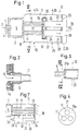
- a burner (1) of a combustion chamber (2) is passed through line (3) H 2 S-containing gas and through line (4) oxygen-containing gas, for example air, oxygen-enriched air or also technically pure oxygen , too.
- oxygen-containing gas for example air, oxygen-enriched air or also technically pure oxygen , too.
- several burners can be assigned to one combustion chamber.
- the combustion chamber (5) of the combustion chamber (2) is provided with fireproof walls, since maximum combustion temperatures of about 1000 to 1800 ° C and usually at least 1200 ° C are set.
- a combustion gas is generated in the combustion chamber (5) which, in addition to SO 2 , H 2 O and residual H 2 S, also contains H 2 and elemental sulfur due to thermal decomposition.
- rapid cooling ensures that the entire hydrogen content does not disappear again due to recombination with sulfur.
- the necessary rapid cooling of the hot gases to a maximum of 800 ° C takes place in the first section (10) of the heat exchanger (6).
- This first section has numerous narrow tubes (11) which are located in the first cooling chamber (12). Cooling fluid, in particular water, is fed to the first cooling space (12) through the line (13), water vapor formed flows off in the line (14). The outlet end of the tubes (11) is held by a first tube plate (15).
- Fig. 2 is the inlet end of a single tube (11) shown, in which the hot combustion gas from the Combustion chamber (5) enters in the direction of arrow (8).
- a ceramic sleeve (9) provided that the cooling liquid surrounding the tube (11) in experience has shown that this inlet area is not sufficiently effective can be.
- (5a) denotes the refractory lining of the Combustion chamber (5).
- the second section (20) of the heat exchanger (6) has one reduced number of gas-carrying pipes (21), two or several pipes (11) of the first section of a pipe (21) of the second section (20).
- the ratio of Diameter d of the tubes (11) to diameter D of the tubes (21) is usually in the range of 1: 2 to 1: 5.
- the tubes (21) of the second section run between a second tube sheet (22) and a third tube sheet (23).
- cooling fluid e.g. Water, too and discharges water vapor through line (26).
- the two tube sheets (15) and (22) are separated by a ring (30) connected gastight, there is a perforated cutting disc (31) between the ring (30) and the housing (7) of the heat exchanger (6) provided.
- This cutting disc (31) ensures that only one low fluid exchange between the first and second Cooling chamber takes place, but the disc (31) is for educated Steam permeable, so that in both cold rooms (12) and (24) there is the same pressure.
- the disc (31) supports the two tube plates (15) and (22) against the housing (7).
- the gas as it flows through the tubes (11) during a residence time of at most 0.05 seconds and preferably at most 0.03 seconds to a temperature in the range is cooled from 500-800 ° C.
- FIG. 1 shows in simplified form, the gas cooled in this way flows from two tubes (11) into a larger tube (21) of the second cooling section and is further cooled there.
- the gas mixture coming from the tubes (21) initially flows into the collecting chamber (28), with the condensate formed being drawn off through the line (29).
- This condensate can contain elemental sulfur, for example.
- the gas which in addition to SO 2 , H 2 O and H 2 S also contains molecular hydrogen, leaves the heat exchanger (6) through the exhaust (33).
- the gas that flows through the exhaust (33) usually has temperatures in the range from 200 to 400 ° C. and can be further catalytically treated in a Claus plant.
- Fig. 3 shows in Section along the line IV-IV (Fig. 3), like three tubes (11) are assigned to a larger pipe (21). Because of stable arrangement, several tubes (21) are supported in the housing (7) of the heat exchanger near its cover (21a) on one perforated partition (31), which is indicated in Fig. 3.
- the first Cold room (12) roof-like guide walls (17) provided that the water vapor formed in sections direct the central area (18).
- This central area (18) the widens in a wedge shape towards the steam outlet (14) kept clear of tubes (11).
- the dashed lines (18a) and (18b) indicate the limits of the middle area (18).
- Fig. 6 shows a heat exchanger with a bypass line (35) from the combustion chamber (2) continuously to Collection chamber (28) is guided.
- the amount of that through the line (35) flowing gas mixture can be controlled by a regulator can be set, which is not shown in the drawing. In this way, the temperature of the gas mixture can be regulate which is further processed after the heat exchanger becomes.
- the other reference numbers have the same as already explained Meaning.
- the heat exchanger in the first section (10) has 279 steel tubes with the dimensions of column A: A B length 1.6 m 6.4 m outer diameter 20 mm 52.5 mm Wall thickness 1.5 mm 3.9 mm
- the combustion chamber (2) of a Claus plant is supplied with gas in accordance with column C of the table below, as well as 4900 Nm 3 / h air and 644 Nm 3 / h technically pure oxygen: C.
- D E F Quantity (Nm 3 / h) 3560 7930 7460 6950 H 2 S (vol%) 77.1 5.2 8.8 7.3 H 2 O (vol%) 12.3 32.5 33.9 38.6 NH 3 (vol%) 5.6 1.1 - - CO (vol%) 4.5 - - - SO 2 (vol%) - 4.0 4.6 3.8 H 2 (vol%) - 4.9 5.2 CO 2 (vol%) 0.5 1.4 - - COS (vol%) - 0.03 ⁇ 0.01 ⁇ 0.01 temperature 40 1416 675 353
- the maximum temperature in the combustion chamber is 1416 ° C.
- a Gas mixture with this temperature and the composition according to Column D of the table above flows through the 279 tubes of the first section, the N portion of the mixture and traces other gases are not included in the table. While a residence time in the tubes (11) of 24 msec Gas mixture cooled to a temperature of 675 ° C. With this Temperature and that given in column E in the table above Components, the gas mixture enters the second section (21) on. Cooled to 353 ° C, the gas mixture leaves with the Components according to column F of the table above the second Section (21) of the heat exchanger, at the same time per Hour 2040 kg of liquid elemental sulfur are withdrawn. The Data from columns D and E were calculated.
Landscapes
- Engineering & Computer Science (AREA)
- Chemical & Material Sciences (AREA)
- Mechanical Engineering (AREA)
- General Engineering & Computer Science (AREA)
- Organic Chemistry (AREA)
- Physics & Mathematics (AREA)
- Thermal Sciences (AREA)
- Combustion & Propulsion (AREA)
- Chemical Kinetics & Catalysis (AREA)
- Inorganic Chemistry (AREA)
- Heat-Exchange Devices With Radiators And Conduit Assemblies (AREA)
- Treating Waste Gases (AREA)
Description
- Fig. 1
- eine Brennkammer mit angeschlossenem Wärmeaustauscherim Längsschnitt in schematischer Darstellung,
- Fig. 2
- den Einlaßbereich eines Rohrs des ersten Abschnitts desWärmeaustauschers im Längsschnitt,
- Fig. 3
- eine Variante der Einmündung mehrerer Röhren des erstenAbschnitts in ein Rohr des zweiten Abschnitts des Wärmeaustauschers im Längsschnitt,
- Fig. 4
- einen Schnitt nach der Linie IV-IV in Fig. 3 in vergrößerter Darstellung,
- Fig. 5
- einen Schnitt nach der Linie V-V in Fig. 1 invergrößerter Darstellung,
- Fig. 6
- einen Wärmeaustauscher mit Bypassleitung und
- Fig. 7
- eine weitere Variante des Wärmeaustauschers.
| A | B | |
| Länge | 1,6 m | 6,4 m |
| Außendurchmesser | 20 mm | 52,5 mm |
| Wandstärke | 1,5 mm | 3,9 mm |
| C | D | E | F | |
| Menge (Nm3/h) | 3560 | 7930 | 7460 | 6950 |
| H2S (Vol%) | 77,1 | 5,2 | 8,8 | 7,3 |
| H2O (Vol%) | 12,3 | 32,5 | 33,9 | 38,6 |
| NH3 (Vol%) | 5,6 | 1,1 | - | - |
| CO (Vol%) | 4,5 | - | - | - |
| SO2 (Vol%) | - | 4,0 | 4,6 | 3,8 |
| H2 (Vol%) | - | 7,2 | 4,9 | 5,2 |
| CO2 (Vol%) | 0,5 | 1,4 | - | - |
| COS (Vol%) | - | 0,03 | < 0,01 | < 0,01 |
| Temperatur | 40 | 1416 | 675 | 353 |
Claims (11)
- Verfahren zum Kühlen eines Verbrennungsgases aus einer Brennkammer, in welcher man ein H2S-haltiges Gas bei einer maximalen Temperatur im Bereich von etwa 1000 bis 1800°C partiell verbrennt, so daß das Verbrennungsgas SO2, H2S H2, H2O, und Elementarschwefel enthält, wobei man das Verbrennungsgas unmittelbar anschließend an die Brennkammer durch einen indirekten Wärmeaustauscher leitet, in dessen Kühlraum ein Kühlfluid zum Abführen der Wärme geleitet wird, dadurch gekennzeichnet, daß man das aus der Brennkammer kommende Verbrennungsgas zunächst im ersten Abschnitt des indirekten Wärmeaustauschers durch zahlreiche Röhren mit kleinem Durchmesser d von 5 bis 50 mm leitet und dabei das Verbrennungsgas auf eine Temperatur von höchstens 800°C während einer Verweilzeit in den Röhren des ersten Abschnitts von höchstens 0,05 Sekunden kühlt und daß man das Verbrennungsgas aus den engen Röhren in Röhren eines zweiten Abschnitts des indirekten Wärmeaustauschers leitet, wobei der Durchmesser D der Röhren des zweiten Abschnitts mindestens 2d beträgt.
- Verfahren nach Anspruch 1, dadurch gekennzeichnet, daß die Kühlung des Verbrennungsgases auf eine Temperatur von höchstens 750°C in den Röhren des ersten Abschnitts während einer Verweilzeit des Gases von höchstens 0,03 Sekunden erreicht wird.
- Verfahren nach Anspruch 1 oder 2, dadurch gekennzeichnet, daß der zum ersten Abschnitt des Wärmeaustauschers gehörende erste Kühlraum eine erste Zuleitung für Kühlfluid und einen ersten Dampfabzug und der zum zweiten Abschnitt des Wärmeaustauschers gehörende zweite Kühlraum eine zweite Zuleitung für Kühlfluid und einen zweiten Dampfabzug besitzt.
- Verfahren nach Anspruch 1 oder einem der folgenden, dadurch gekennzeichnet, daß der Druck in den von Kühlfluid durchströmten Räumen des Wärmeaustauschers gleich ist.
- Brennkammer für das partielle Verbrennen eines H2S-haltigen Gases bei maximalen Temperaturen im Bereich von etwa 1000 bis 1800°C zur Erzeugung eines SO2, H2S, H2, H2O und Elementarschwefel enthaltenden Verbrennungsgases, mit einem mit der Brennkammer direkt verbundenen indirekten Wärmeaustauscher mit zahlreichen Röhren, in welche das Verbrennungsgas aus der Brennkammer direkt eintritt, wobei Wärme durch ein Kühlfluid abgeführt wird, welches einem die Röhren umgebenden Kühlraum zugeführt wird und wobei der Wärmeaustauscher einen an die Brennkammer anschließenden ersten Abschnitt und einen mit dem ersten Abschnitt verbundenen zweiten Abschnitt aufweist, dadurch gekennzeichnet, daß der erste Abschnitt zahlreiche Röhren mit kleinem Durchmesser d von 5 bis 50 mm aufweist, daß der zweite Abschnitt Röhren mit größerem Durchmesser D aufweist, wobei D mindestens gleich 2d ist, daß die Auslaßenden der Röhren des ersten Abschnitts im Eintrittsbereich der Röhren des zweiten Abschnitts liegen und daß jeder Abschnitt mindestens eine Zuleitung für Kühlfluid aufweist.
- Brennkammer nach Anspruch 5, dadurch gekennzeichnet, daß die Röhren des ersten Abschnitts in der Nähe ihres Auslaßendes durch einen ersten Rohrboden und die Röhren des zweiten Abschnitts in der Nähe ihres Eintrittsendes durch einen zweiten Rohrboden geführt sind und daß die beiden Rohrböden miteinander verbunden sind.
- Brennkammer nach Anspruch 5, dadurch gekennzeichnet, daß die Röhren des zweiten Abschnitts an ihrem Eintrittsende jeweils mit einem Deckel versehen sind und daß durch einen Deckel die Auslaßenden von mindestens zwei Röhren des ersten Abschnitts hindurchgeführt sind. Auslaßenden von mindestens zwei Röhren des ersten Abschnitts hindurchgeführt sind.
- Brennkammer nach einem der Ansprüche 5 bis 7, dadurch gekennzeichnet, daß der zum ersten Abschnitt gehörende erste Kühlraum vom zweiten Kühlraum, der zum zweiten Abschnitt gehört, durch eine gasdurchlässige Wand teilweise abgetrennt ist.
- Brennkammer nach einem der Ansprüche 5 bis 8, dadurch gekennzeichnet, daß der Kühlraum des ersten Abschnitts dachartig angeordnete Führungswände aufweist.
- Brennkammer nach Anspruch 5, dadurch gekennzeichnet, daß der erste und zweite Abschnitt übereinander oder nebeneinander angeordnet sind und die Auslaßenden der Röhren der ersten Abschnitts und die Einlaßenden der Röhren des zweiten Abschnitts durch eine Zwischenkammer verbunden sind.
- Brennkammer nach einem der Ansprüche 5 - 10, dadurch gekennzeichnet, daß eine Bypassleitung durch den ersten und zweiten Abschnitt geführt ist.
Applications Claiming Priority (2)
| Application Number | Priority Date | Filing Date | Title |
|---|---|---|---|
| DE19520394A DE19520394A1 (de) | 1995-06-08 | 1995-06-08 | Verfahren und Vorrichtung zum schnellen Kühlen eines Wasserstoff und Elementarschwefel enthaltenden heißen Gasgemisches |
| DE19520394 | 1995-06-08 |
Publications (2)
| Publication Number | Publication Date |
|---|---|
| EP0747318A1 EP0747318A1 (de) | 1996-12-11 |
| EP0747318B1 true EP0747318B1 (de) | 1999-05-26 |
Family
ID=7763597
Family Applications (1)
| Application Number | Title | Priority Date | Filing Date |
|---|---|---|---|
| EP96106066A Expired - Lifetime EP0747318B1 (de) | 1995-06-08 | 1996-04-18 | Verfahren und Vorrichtung zum schnellen Kühlen eines Wasserstoff und Elementarschwefel enthaltenden heissen Gasgemisches |
Country Status (3)
| Country | Link |
|---|---|
| EP (1) | EP0747318B1 (de) |
| CA (1) | CA2176617A1 (de) |
| DE (2) | DE19520394A1 (de) |
Families Citing this family (3)
| Publication number | Priority date | Publication date | Assignee | Title |
|---|---|---|---|---|
| GB2392907B (en) * | 2002-09-12 | 2007-01-17 | Amer Sarssam | A process for the recovery of sulphur from gas streams containing hydrogen sulphide |
| ITUD20060217A1 (it) * | 2006-09-27 | 2008-03-28 | Gen & Marine Applic S R L | Apparecchiatura per il rivestimento interno di condutture, e relativo procedimento |
| WO2018170514A1 (en) * | 2017-03-17 | 2018-09-20 | Beckett Gas, Inc. | Heat exchanger |
Family Cites Families (7)
| Publication number | Priority date | Publication date | Assignee | Title |
|---|---|---|---|---|
| US2836481A (en) * | 1951-03-06 | 1958-05-27 | Shell Dev | Method and apparatus for the combustion of hydrogen sulfide and the production of sulfur |
| US2834655A (en) * | 1955-09-09 | 1958-05-13 | Parsons Co Ralph M | Production of elemental sulfur |
| GB1054128A (de) * | 1963-08-14 | |||
| FR2198888A1 (en) * | 1972-09-08 | 1974-04-05 | Bogossian Antoi E | Sulphur recovery from gas mixt - contg hydrogen sulphide and hydrocarbons |
| US4207304A (en) * | 1977-06-27 | 1980-06-10 | The Ralph M. Parsons Company | Process for sulfur production |
| US4481181A (en) * | 1982-02-08 | 1984-11-06 | Ga Technologies Inc. | Hydrogen production from in situ partial burning of H2 S |
| JPH01270502A (ja) * | 1988-04-20 | 1989-10-27 | Jgc Corp | 硫化水素から水素を製造する方法 |
-
1995
- 1995-06-08 DE DE19520394A patent/DE19520394A1/de not_active Withdrawn
-
1996
- 1996-04-18 DE DE59601979T patent/DE59601979D1/de not_active Expired - Lifetime
- 1996-04-18 EP EP96106066A patent/EP0747318B1/de not_active Expired - Lifetime
- 1996-05-14 CA CA002176617A patent/CA2176617A1/en not_active Abandoned
Also Published As
| Publication number | Publication date |
|---|---|
| CA2176617A1 (en) | 1996-12-09 |
| EP0747318A1 (de) | 1996-12-11 |
| DE59601979D1 (de) | 1999-07-01 |
| DE19520394A1 (de) | 1996-12-12 |
Similar Documents
| Publication | Publication Date | Title |
|---|---|---|
| DE60103070T2 (de) | Verfahren und vorrichtung zur gewinnung von schwefel aus schwefelwasserstoff enthaltenden gasströmen | |
| DE69603970T2 (de) | Wärmeaustauschvorrichtung und -verfahren | |
| DE60030156T2 (de) | Teiloxidation eines schwefelwasserstoff enthaltenden gasstroms | |
| DE602004004908T2 (de) | Vorrichtung und verfahren zum kühlen von heissgas | |
| DE2933514C2 (de) | Vorrichtung zum Behandeln von durch Kohlevergasung erzeugtem Synthesegas | |
| DE2711897C3 (de) | Verfahren und Vorrichtung zur katalytischen Oxidation von gasförmigen Schwefelverbindungen zu Schwefeltrioxid | |
| EP0458183A2 (de) | Verfahren zur verbesserten Bereitstellung von Behandlungsgas bei Wärmebehandlungen | |
| DE3208467A1 (de) | Konvektionserhitzer zum erhitzen von fluida, wie z.b. eine aufschlaemmung oder dergleichen | |
| DE2727971A1 (de) | Verfahren und vorrichtung zur thermischen behandlung einer warenbahn | |
| DD262063A5 (de) | Verfahren und vorrichtung zum erhitzen von aus kuehlwasser gebildetem dampf | |
| DE60313441T2 (de) | Partialoxidation von schwefelwasserstoff | |
| EP0747318A1 (de) | Verfahren und Vorrichtung zum schnellen Kühlen eines Wasserstoff und Elementarschwefel enthaltenden heissen Gasgemisches | |
| EP0418534A2 (de) | Wärmetauscher zum Kühlen von Reaktionsgas | |
| DE2241891A1 (de) | Verfahren und vorrichtung zur verbrennung von vorzugsweise bei der reinigung von koksofengasen anfallenden gasund dampfgemischen, insbes. sog. ammoniakschwaden | |
| DE69612204T2 (de) | Verfahren zur katalytischen Konvertierung von Kohlenmonoxid mit hohem Wirkungsgrad | |
| DE69300290T2 (de) | Verfahren und Vorrichtung zur thermischen Behandlung von Abfällen, insbesondere festen Abfällen, welche organische Materialien enthalten. | |
| EP1554522B1 (de) | Verfahren zum betreiben eines dampferzeugers in liegender bauweise | |
| DE3808729A1 (de) | Verfahren und vorrichtung zur abkuehlung des aus einem vergasungsreaktor austretenden heissen produktgases | |
| DE2638274A1 (de) | Mit abwaerme beheizter siedekessel | |
| DE2537948C2 (de) | Vorrichtung zur Vergasung von Kohlenstoff enthaltenden Brennstoffstaub | |
| DE3121297C2 (de) | Vorrichtung zum Regeln der Temperatur eines korrosiven Gases, insbesondere Synthesegas | |
| DE1467119B2 (de) | Verfahren und vorrichtung zur rueckgewinnung von elementarem schwefel aus einem schwefelwasserstoffhaltigen gasstrom mit einem geringen gehalt an brennbaren stoffen | |
| DE3621814C2 (de) | Vorrichtung zur Wärme- und Oberflächenbehandlung von Metallteilen | |
| DE10102963C1 (de) | Verfahren zum Druckausgleich bei einer Kohlevergasungsanlage und Kohlevergasungsanlage zur Durchführung des Verfahrens | |
| EP0369556B1 (de) | Verfahren zur indirekten Erwärmung eines Prozessgasstroms in einem Reaktionsraum für eine endotherme Reaktion und Vorrichtung zu dessen Durchführung |
Legal Events
| Date | Code | Title | Description |
|---|---|---|---|
| PUAI | Public reference made under article 153(3) epc to a published international application that has entered the european phase |
Free format text: ORIGINAL CODE: 0009012 |
|
| AK | Designated contracting states |
Kind code of ref document: A1 Designated state(s): DE FR GB IT NL |
|
| 17P | Request for examination filed |
Effective date: 19970611 |
|
| 17Q | First examination report despatched |
Effective date: 19970711 |
|
| GRAG | Despatch of communication of intention to grant |
Free format text: ORIGINAL CODE: EPIDOS AGRA |
|
| GRAG | Despatch of communication of intention to grant |
Free format text: ORIGINAL CODE: EPIDOS AGRA |
|
| GRAH | Despatch of communication of intention to grant a patent |
Free format text: ORIGINAL CODE: EPIDOS IGRA |
|
| RAP1 | Party data changed (applicant data changed or rights of an application transferred) |
Owner name: METALLGESELLSCHAFT AKTIENGESELLSCHAFT |
|
| GRAH | Despatch of communication of intention to grant a patent |
Free format text: ORIGINAL CODE: EPIDOS IGRA |
|
| GRAA | (expected) grant |
Free format text: ORIGINAL CODE: 0009210 |
|
| AK | Designated contracting states |
Kind code of ref document: B1 Designated state(s): DE FR GB IT NL |
|
| REF | Corresponds to: |
Ref document number: 59601979 Country of ref document: DE Date of ref document: 19990701 |
|
| ET | Fr: translation filed | ||
| ITF | It: translation for a ep patent filed | ||
| GBT | Gb: translation of ep patent filed (gb section 77(6)(a)/1977) |
Effective date: 19990819 |
|
| PGFP | Annual fee paid to national office [announced via postgrant information from national office to epo] |
Ref country code: GB Payment date: 20000313 Year of fee payment: 5 |
|
| PGFP | Annual fee paid to national office [announced via postgrant information from national office to epo] |
Ref country code: NL Payment date: 20000320 Year of fee payment: 5 Ref country code: DE Payment date: 20000320 Year of fee payment: 5 |
|
| PGFP | Annual fee paid to national office [announced via postgrant information from national office to epo] |
Ref country code: FR Payment date: 20000327 Year of fee payment: 5 |
|
| PLBE | No opposition filed within time limit |
Free format text: ORIGINAL CODE: 0009261 |
|
| STAA | Information on the status of an ep patent application or granted ep patent |
Free format text: STATUS: NO OPPOSITION FILED WITHIN TIME LIMIT |
|
| 26N | No opposition filed | ||
| PG25 | Lapsed in a contracting state [announced via postgrant information from national office to epo] |
Ref country code: DE Free format text: LAPSE BECAUSE OF THE APPLICANT RENOUNCES Effective date: 20001205 |
|
| PG25 | Lapsed in a contracting state [announced via postgrant information from national office to epo] |
Ref country code: GB Free format text: LAPSE BECAUSE OF NON-PAYMENT OF DUE FEES Effective date: 20010418 |
|
| PG25 | Lapsed in a contracting state [announced via postgrant information from national office to epo] |
Ref country code: FR Free format text: THE PATENT HAS BEEN ANNULLED BY A DECISION OF A NATIONAL AUTHORITY Effective date: 20010430 |
|
| PG25 | Lapsed in a contracting state [announced via postgrant information from national office to epo] |
Ref country code: NL Free format text: LAPSE BECAUSE OF NON-PAYMENT OF DUE FEES Effective date: 20011101 |
|
| GBPC | Gb: european patent ceased through non-payment of renewal fee |
Effective date: 20010418 |
|
| NLV4 | Nl: lapsed or anulled due to non-payment of the annual fee |
Effective date: 20011101 |
|
| REG | Reference to a national code |
Ref country code: FR Ref legal event code: ST |
|
| PG25 | Lapsed in a contracting state [announced via postgrant information from national office to epo] |
Ref country code: IT Free format text: LAPSE BECAUSE OF NON-PAYMENT OF DUE FEES Effective date: 20050418 |