EP0747263A2 - Interrupteur de colonne de direction avec blocage pour éviter une commande non intentionnelle - Google Patents
Interrupteur de colonne de direction avec blocage pour éviter une commande non intentionnelle Download PDFInfo
- Publication number
- EP0747263A2 EP0747263A2 EP96107468A EP96107468A EP0747263A2 EP 0747263 A2 EP0747263 A2 EP 0747263A2 EP 96107468 A EP96107468 A EP 96107468A EP 96107468 A EP96107468 A EP 96107468A EP 0747263 A2 EP0747263 A2 EP 0747263A2
- Authority
- EP
- European Patent Office
- Prior art keywords
- rotary shaft
- switch
- shift lever
- steering column
- projection
- Prior art date
- Legal status (The legal status is an assumption and is not a legal conclusion. Google has not performed a legal analysis and makes no representation as to the accuracy of the status listed.)
- Granted
Links
- 238000005266 casting Methods 0.000 description 1
- 230000006870 function Effects 0.000 description 1
- 238000005286 illumination Methods 0.000 description 1
- 230000009131 signaling function Effects 0.000 description 1
Images
Classifications
-
- B—PERFORMING OPERATIONS; TRANSPORTING
- B60—VEHICLES IN GENERAL
- B60Q—ARRANGEMENT OF SIGNALLING OR LIGHTING DEVICES, THE MOUNTING OR SUPPORTING THEREOF OR CIRCUITS THEREFOR, FOR VEHICLES IN GENERAL
- B60Q1/00—Arrangement of optical signalling or lighting devices, the mounting or supporting thereof or circuits therefor
- B60Q1/02—Arrangement of optical signalling or lighting devices, the mounting or supporting thereof or circuits therefor the devices being primarily intended to illuminate the way ahead or to illuminate other areas of way or environments
- B60Q1/04—Arrangement of optical signalling or lighting devices, the mounting or supporting thereof or circuits therefor the devices being primarily intended to illuminate the way ahead or to illuminate other areas of way or environments the devices being headlights
- B60Q1/14—Arrangement of optical signalling or lighting devices, the mounting or supporting thereof or circuits therefor the devices being primarily intended to illuminate the way ahead or to illuminate other areas of way or environments the devices being headlights having dimming means
- B60Q1/1446—Arrangement of optical signalling or lighting devices, the mounting or supporting thereof or circuits therefor the devices being primarily intended to illuminate the way ahead or to illuminate other areas of way or environments the devices being headlights having dimming means controlled by mechanically actuated switches
- B60Q1/1453—Hand actuated switches
- B60Q1/1461—Multifunction switches for dimming headlights and controlling additional devices, e.g. for controlling direction indicating lights
- B60Q1/1469—Multifunction switches for dimming headlights and controlling additional devices, e.g. for controlling direction indicating lights controlled by or attached to a single lever, e.g. steering column stalk switches
Definitions
- the invention relates to a steering column switch, in the shift lever of which a shift shaft is rotatably mounted.
- the steering column switch can be used to operate two mutually independent switches in the switch housing by means of a pivoting movement in at least a first plane and by rotating the rotary shaft relative to the shift lever.
- Such a switch is known for example from DE-OS 40 20 844.
- the shift lever can also be pivoted in a second plane and thus allows the independent actuation of a third switch in the switch housing, it cannot be ruled out that the driver, in particular in critical driving situations, operates the steering column switch incorrectly.
- the car lamps usually operated with the steering column switch not only have illumination functions in the dark but can also have warning and signal functions at the same time.
- the object of the invention is therefore to prevent in a generic switch that the rotary shaft can be actuated when the shift lever is in at least a certain pivot position.
- the object is achieved by the combination of features resulting from the characterizing part of claim 1.
- the invention consists in principle in the fact that in the position of the shift lever, in which no rotation of the rotary shaft should be possible, preferably mechanical locking ensures that in this pivoted position of the shift lever, the rotary shaft is not actually rotated relative to the shift lever can.
- a particularly simple embodiment of the desired locking option results from the combination of features according to claim 2, since it is achieved here that a projection can engage in a corresponding opening of the rotary shaft.
- the attachment of the projection does not have to be directly on the switch housing, as will be explained with reference to the following features. It is important that the rotary shaft maintains a relatively simple shape and does not have any larger additional parts protruding from it that enable the locking.
- the invention is particularly advantageously used in accordance with the combination of features according to claim 4 for steering column switches in which the shift lever can be pivoted in two different planes, the pivoting taking place within the additional second plane in a manner known per se via a driver in the switch housing.
- the first projection is not attached directly to the switch housing but to the driver itself. This can be done by a one-piece attachment, for example by casting the first projection onto the driver.
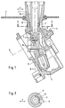
- Fig. 1 shows the shift lever 1, which is connected to an elastic cover 2, which on the one hand keeps dirt away from the switch system, but on the other hand does not hinder a pivoting movement of the shift lever 1.
- the pivoting can also be in the direction of the double arrow F and perpendicular to this about a pivot axis G.
- the end of the shift lever 1 which projects downward in FIG. 1 is immersed in a driver 3 which can be pivoted about the axis of rotation G via pins (for example pins 4) in the switch housing (not shown). This allows the shift lever 1 to pivot perpendicular to the pivoting direction F.
- the lower end of the shift lever is leveled in a manner known per se with a resiliently pretensioned shift drum which, in cooperation with a shift contour, creates 5 latching positions for shift lever 1, to which certain pivot positions of the shift lever are assigned.
- a rotary shaft 6 is rotatably mounted about its longitudinal axis K, so that a second switching system, not shown in the figure, can be actuated within the switching housing by its rotational movement.
- first recess 7 in the rotary shaft 6 into which a first projection 8 of the driver 3 projects (see also FIG. 2).
- the engagement of the projection 8 in the recess 7 takes place in that the shift lever 1 is pivoted in the direction of the right arrow F, in Fig. 1 to the right.
- the shift lever is pivoted to the left in the direction of the left arrow F, the projection 8 disengages so that the rotary shaft 6 is rotated relative to the shift lever 1 about the longitudinal axis K and thus the Actuation of the associated switching system can be achieved.
- the projection 8 is outside the plane of symmetry of the shift lever 1. It can also be seen from FIG. 2 that the recess in the direction of the sectional plane of FIG. 2 has a substantially triangular cross section. However, as can be seen from FIG. A, the recess 7 can completely break through the sleeve-shaped wall 12.
- additional recesses 10 and 11 can also be provided, which are assigned to the different rotational positions of the rotary shaft relative to the shift lever 1 and in these shift positions lock the rotary shaft relative to the shift lever at a corresponding pivot position.
- the rotary shaft is composed of two non-detachably connected parts, namely the actuating sleeve 13 and an actuating member 14.
- the shift lever is pivotable about the axis of rotation S perpendicular to the viewing plane of FIG. 1.
Landscapes
- Engineering & Computer Science (AREA)
- Mechanical Engineering (AREA)
- Arrangement Or Mounting Of Control Devices For Change-Speed Gearing (AREA)
Applications Claiming Priority (2)
| Application Number | Priority Date | Filing Date | Title |
|---|---|---|---|
| DE19521085A DE19521085A1 (de) | 1995-06-09 | 1995-06-09 | Lenkstockschalter mit Sperre gegen unbeabsichtigtes Schalten |
| DE19521085 | 1995-06-09 |
Publications (3)
| Publication Number | Publication Date |
|---|---|
| EP0747263A2 true EP0747263A2 (fr) | 1996-12-11 |
| EP0747263A3 EP0747263A3 (fr) | 1997-11-05 |
| EP0747263B1 EP0747263B1 (fr) | 2001-02-07 |
Family
ID=7764019
Family Applications (1)
| Application Number | Title | Priority Date | Filing Date |
|---|---|---|---|
| EP96107468A Expired - Lifetime EP0747263B1 (fr) | 1995-06-09 | 1996-05-10 | Interrupteur de colonne de direction avec blocage pour éviter une commande non intentionnelle |
Country Status (2)
| Country | Link |
|---|---|
| EP (1) | EP0747263B1 (fr) |
| DE (2) | DE19521085A1 (fr) |
Cited By (1)
| Publication number | Priority date | Publication date | Assignee | Title |
|---|---|---|---|---|
| EP2055529A1 (fr) * | 2007-11-02 | 2009-05-06 | Delphi Technologies, Inc. | Dispositif de commutation |
Citations (1)
| Publication number | Priority date | Publication date | Assignee | Title |
|---|---|---|---|---|
| DE4020844A1 (de) | 1990-06-29 | 1992-01-09 | Swf Auto Electric Gmbh | Elektrischer schalter, insbesondere lenkstockschalter fuer kraftfahrzeuge |
Family Cites Families (3)
| Publication number | Priority date | Publication date | Assignee | Title |
|---|---|---|---|---|
| FR2199709A5 (fr) * | 1972-09-20 | 1974-04-12 | Tecalemit Sa | |
| GB1602606A (en) * | 1977-09-13 | 1981-11-11 | Lucas Industries Ltd | Electrical switch |
| FR2657456B1 (fr) * | 1990-01-25 | 1993-09-24 | Neiman Sa | Commutateur electrique bistable, notamment pour la commande de l'eclairage d'un vehicule automobile. |
-
1995
- 1995-06-09 DE DE19521085A patent/DE19521085A1/de not_active Withdrawn
-
1996
- 1996-05-10 DE DE59606417T patent/DE59606417D1/de not_active Expired - Fee Related
- 1996-05-10 EP EP96107468A patent/EP0747263B1/fr not_active Expired - Lifetime
Patent Citations (1)
| Publication number | Priority date | Publication date | Assignee | Title |
|---|---|---|---|---|
| DE4020844A1 (de) | 1990-06-29 | 1992-01-09 | Swf Auto Electric Gmbh | Elektrischer schalter, insbesondere lenkstockschalter fuer kraftfahrzeuge |
Cited By (1)
| Publication number | Priority date | Publication date | Assignee | Title |
|---|---|---|---|---|
| EP2055529A1 (fr) * | 2007-11-02 | 2009-05-06 | Delphi Technologies, Inc. | Dispositif de commutation |
Also Published As
| Publication number | Publication date |
|---|---|
| DE59606417D1 (de) | 2001-03-15 |
| DE19521085A1 (de) | 1996-12-12 |
| EP0747263A3 (fr) | 1997-11-05 |
| EP0747263B1 (fr) | 2001-02-07 |
Similar Documents
| Publication | Publication Date | Title |
|---|---|---|
| DE3834390C1 (fr) | ||
| DE4426207C5 (de) | Wähleinrichtung für ein Automatikgetriebe eines Kraftfahrzeugs | |
| DE19758288B4 (de) | Verfahren und Vorrichtung zur drehrichtungsgekoppelten Rückstellung eines Schalters | |
| DE10233956B4 (de) | Multifunktions-Hebelschalter | |
| DE2259484C3 (de) | Schaltblock für die Armaturentafel eines Fahrzeugs | |
| DE69102456T3 (de) | Schalthebelgriff mit zwei Drehringen, insbesondere für Kraftfahrzeugschaltern. | |
| DE3525091A1 (de) | Saevorrichtung | |
| DE4436096C2 (de) | Klinkenschaltwerk zum Antrieb einer Verstellvorrichtungen für einen Fahrzeugsitz | |
| EP0460155B1 (fr) | Commutateur electrique, notamment commutateur de clignotant de vehicules a moteur | |
| EP0747263B1 (fr) | Interrupteur de colonne de direction avec blocage pour éviter une commande non intentionnelle | |
| DE10238269A1 (de) | Lenksäulenholm mit mehreren Schalterzellen | |
| EP1117950A1 (fr) | Dispositif de commutation pour boite automatique d'un vehicule a moteur | |
| DE1780460C3 (de) | Richtungsanzeigevorrichtung für Kraftfahrzeuge | |
| EP0782510B1 (fr) | Commutateur monte sur la colonne de direction, servant d'organe de changement de vitesses avec possibilite de fixation en position neutre | |
| DE4016773A1 (de) | Elektrischer schalter, insbesondere zum betreiben einer scheibenwisch- und einer scheibenwaschanlage eines kraftfahrzeugs | |
| EP0873254B1 (fr) | Systeme empechant la rupture pour interrupteur sur colonne de direction a retour automatique au point neutre | |
| DE60203864T2 (de) | Hebelschalter für Fahrzeuge | |
| DE1958956C3 (de) | Fahrtrichtungsanzeigeschalter mit selbsttätiger Rückstellung durch die Lenkeinrichtung | |
| DE3129004C2 (de) | Schalteranordnung, insbesondere einen Lenkstockschalter für Kraftfahrzeuge | |
| WO1992000205A1 (fr) | Commutateur electrique, notamment commutateur fixe a la colonne de direction de vehicules a moteur | |
| DE19918566B4 (de) | Blinkerhebelvorrichtung | |
| DE2815255A1 (de) | Anzeigevorrichtung fuer druckknopfschalter | |
| DE3430664C2 (fr) | ||
| DE2725301C2 (de) | Kraftfahrzeugschalter für die Einschaltung von Fahrtrichtungsanzeigern und Parklicht mit einem um eine Drehachse schwenkbaren Umschalt-Handhebel | |
| DE69915408T2 (de) | Schalthebelvorrichtung |
Legal Events
| Date | Code | Title | Description |
|---|---|---|---|
| PUAI | Public reference made under article 153(3) epc to a published international application that has entered the european phase |
Free format text: ORIGINAL CODE: 0009012 |
|
| AK | Designated contracting states |
Kind code of ref document: A2 Designated state(s): DE FR GB IT |
|
| PUAL | Search report despatched |
Free format text: ORIGINAL CODE: 0009013 |
|
| AK | Designated contracting states |
Kind code of ref document: A3 Designated state(s): DE FR GB IT |
|
| 17P | Request for examination filed |
Effective date: 19980506 |
|
| 17Q | First examination report despatched |
Effective date: 19990928 |
|
| GRAG | Despatch of communication of intention to grant |
Free format text: ORIGINAL CODE: EPIDOS AGRA |
|
| GRAG | Despatch of communication of intention to grant |
Free format text: ORIGINAL CODE: EPIDOS AGRA |
|
| GRAH | Despatch of communication of intention to grant a patent |
Free format text: ORIGINAL CODE: EPIDOS IGRA |
|
| GRAH | Despatch of communication of intention to grant a patent |
Free format text: ORIGINAL CODE: EPIDOS IGRA |
|
| RAP1 | Party data changed (applicant data changed or rights of an application transferred) |
Owner name: VALEO SCHALTER UND SENSOREN GMBH |
|
| GRAA | (expected) grant |
Free format text: ORIGINAL CODE: 0009210 |
|
| RIN1 | Information on inventor provided before grant (corrected) |
Inventor name: KLEIN, RUDOLF Inventor name: HECHT, WALTER Inventor name: SIMONIS, KARL Inventor name: CRISTOFARO, SALVADOR |
|
| AK | Designated contracting states |
Kind code of ref document: B1 Designated state(s): DE FR GB IT |
|
| PG25 | Lapsed in a contracting state [announced via postgrant information from national office to epo] |
Ref country code: IT Free format text: LAPSE BECAUSE OF FAILURE TO SUBMIT A TRANSLATION OF THE DESCRIPTION OR TO PAY THE FEE WITHIN THE PRESCRIBED TIME-LIMIT;WARNING: LAPSES OF ITALIAN PATENTS WITH EFFECTIVE DATE BEFORE 2007 MAY HAVE OCCURRED AT ANY TIME BEFORE 2007. THE CORRECT EFFECTIVE DATE MAY BE DIFFERENT FROM THE ONE RECORDED. Effective date: 20010207 Ref country code: GB Free format text: LAPSE BECAUSE OF FAILURE TO SUBMIT A TRANSLATION OF THE DESCRIPTION OR TO PAY THE FEE WITHIN THE PRESCRIBED TIME-LIMIT Effective date: 20010207 |
|
| REF | Corresponds to: |
Ref document number: 59606417 Country of ref document: DE Date of ref document: 20010315 |
|
| ET | Fr: translation filed | ||
| GBV | Gb: ep patent (uk) treated as always having been void in accordance with gb section 77(7)/1977 [no translation filed] |
Effective date: 20010207 |
|
| PLBE | No opposition filed within time limit |
Free format text: ORIGINAL CODE: 0009261 |
|
| STAA | Information on the status of an ep patent application or granted ep patent |
Free format text: STATUS: NO OPPOSITION FILED WITHIN TIME LIMIT |
|
| 26N | No opposition filed | ||
| PGFP | Annual fee paid to national office [announced via postgrant information from national office to epo] |
Ref country code: DE Payment date: 20080514 Year of fee payment: 13 |
|
| REG | Reference to a national code |
Ref country code: FR Ref legal event code: ST Effective date: 20100129 |
|
| PG25 | Lapsed in a contracting state [announced via postgrant information from national office to epo] |
Ref country code: FR Free format text: LAPSE BECAUSE OF NON-PAYMENT OF DUE FEES Effective date: 20090602 |
|
| PGFP | Annual fee paid to national office [announced via postgrant information from national office to epo] |
Ref country code: FR Payment date: 20080430 Year of fee payment: 13 |
|
| PG25 | Lapsed in a contracting state [announced via postgrant information from national office to epo] |
Ref country code: DE Free format text: LAPSE BECAUSE OF NON-PAYMENT OF DUE FEES Effective date: 20091201 |