EP0746357B1 - Externe haltevorrichtung für einen ernährungsschlauch - Google Patents
Externe haltevorrichtung für einen ernährungsschlauch Download PDFInfo
- Publication number
- EP0746357B1 EP0746357B1 EP93917263A EP93917263A EP0746357B1 EP 0746357 B1 EP0746357 B1 EP 0746357B1 EP 93917263 A EP93917263 A EP 93917263A EP 93917263 A EP93917263 A EP 93917263A EP 0746357 B1 EP0746357 B1 EP 0746357B1
- Authority
- EP
- European Patent Office
- Prior art keywords
- tube
- retaining device
- feeding tube
- external retaining
- external
- Prior art date
- Legal status (The legal status is an assumption and is not a legal conclusion. Google has not performed a legal analysis and makes no representation as to the accuracy of the status listed.)
- Expired - Lifetime
Links
- 230000000295 complement effect Effects 0.000 claims description 2
- 210000003491 skin Anatomy 0.000 description 17
- 210000002784 stomach Anatomy 0.000 description 11
- 235000016709 nutrition Nutrition 0.000 description 6
- 239000007788 liquid Substances 0.000 description 4
- 210000001519 tissue Anatomy 0.000 description 4
- 210000000936 intestine Anatomy 0.000 description 3
- 230000035764 nutrition Effects 0.000 description 3
- 229920002379 silicone rubber Polymers 0.000 description 3
- 239000004945 silicone rubber Substances 0.000 description 3
- 210000003815 abdominal wall Anatomy 0.000 description 2
- 239000013536 elastomeric material Substances 0.000 description 2
- 210000002615 epidermis Anatomy 0.000 description 2
- 239000000463 material Substances 0.000 description 2
- 210000004877 mucosa Anatomy 0.000 description 2
- 208000028771 Facial injury Diseases 0.000 description 1
- 206010058522 Oesophageal injury Diseases 0.000 description 1
- 208000003443 Unconsciousness Diseases 0.000 description 1
- 239000000853 adhesive Substances 0.000 description 1
- 230000001070 adhesive effect Effects 0.000 description 1
- 230000000712 assembly Effects 0.000 description 1
- 238000000429 assembly Methods 0.000 description 1
- 230000008901 benefit Effects 0.000 description 1
- 235000019577 caloric intake Nutrition 0.000 description 1
- 230000008859 change Effects 0.000 description 1
- 230000003247 decreasing effect Effects 0.000 description 1
- 235000013305 food Nutrition 0.000 description 1
- 210000001156 gastric mucosa Anatomy 0.000 description 1
- 230000036541 health Effects 0.000 description 1
- 230000000968 intestinal effect Effects 0.000 description 1
- 239000002085 irritant Substances 0.000 description 1
- 231100000021 irritant Toxicity 0.000 description 1
- 210000001630 jejunum Anatomy 0.000 description 1
- 230000000670 limiting effect Effects 0.000 description 1
- 235000021056 liquid food Nutrition 0.000 description 1
- 238000004519 manufacturing process Methods 0.000 description 1
- 235000012054 meals Nutrition 0.000 description 1
- 238000000034 method Methods 0.000 description 1
- 230000004048 modification Effects 0.000 description 1
- 238000012986 modification Methods 0.000 description 1
- 238000000465 moulding Methods 0.000 description 1
- 210000003205 muscle Anatomy 0.000 description 1
- 230000002572 peristaltic effect Effects 0.000 description 1
- 210000004303 peritoneum Anatomy 0.000 description 1
- 229920000915 polyvinyl chloride Polymers 0.000 description 1
- 239000004800 polyvinyl chloride Substances 0.000 description 1
- 230000008569 process Effects 0.000 description 1
- 230000004044 response Effects 0.000 description 1
- 230000000284 resting effect Effects 0.000 description 1
- 239000007787 solid Substances 0.000 description 1
Images

Classifications
-
- A—HUMAN NECESSITIES
- A61—MEDICAL OR VETERINARY SCIENCE; HYGIENE
- A61J—CONTAINERS SPECIALLY ADAPTED FOR MEDICAL OR PHARMACEUTICAL PURPOSES; DEVICES OR METHODS SPECIALLY ADAPTED FOR BRINGING PHARMACEUTICAL PRODUCTS INTO PARTICULAR PHYSICAL OR ADMINISTERING FORMS; DEVICES FOR ADMINISTERING FOOD OR MEDICINES ORALLY; BABY COMFORTERS; DEVICES FOR RECEIVING SPITTLE
- A61J15/00—Feeding-tubes for therapeutic purposes
- A61J15/0015—Gastrostomy feeding-tubes
-
- A—HUMAN NECESSITIES
- A61—MEDICAL OR VETERINARY SCIENCE; HYGIENE
- A61J—CONTAINERS SPECIALLY ADAPTED FOR MEDICAL OR PHARMACEUTICAL PURPOSES; DEVICES OR METHODS SPECIALLY ADAPTED FOR BRINGING PHARMACEUTICAL PRODUCTS INTO PARTICULAR PHYSICAL OR ADMINISTERING FORMS; DEVICES FOR ADMINISTERING FOOD OR MEDICINES ORALLY; BABY COMFORTERS; DEVICES FOR RECEIVING SPITTLE
- A61J15/00—Feeding-tubes for therapeutic purposes
- A61J15/0026—Parts, details or accessories for feeding-tubes
- A61J15/0053—Means for fixing the tube outside of the body, e.g. by a special shape, by fixing it to the skin
- A61J15/0061—Means for fixing the tube outside of the body, e.g. by a special shape, by fixing it to the skin fixing at an intermediate position on the tube, i.e. tube protruding the fixing means
-
- A—HUMAN NECESSITIES
- A61—MEDICAL OR VETERINARY SCIENCE; HYGIENE
- A61J—CONTAINERS SPECIALLY ADAPTED FOR MEDICAL OR PHARMACEUTICAL PURPOSES; DEVICES OR METHODS SPECIALLY ADAPTED FOR BRINGING PHARMACEUTICAL PRODUCTS INTO PARTICULAR PHYSICAL OR ADMINISTERING FORMS; DEVICES FOR ADMINISTERING FOOD OR MEDICINES ORALLY; BABY COMFORTERS; DEVICES FOR RECEIVING SPITTLE
- A61J15/00—Feeding-tubes for therapeutic purposes
- A61J15/0026—Parts, details or accessories for feeding-tubes
- A61J15/0069—Tubes feeding directly to the intestines, e.g. to the jejunum
-
- A—HUMAN NECESSITIES
- A61—MEDICAL OR VETERINARY SCIENCE; HYGIENE
- A61M—DEVICES FOR INTRODUCING MEDIA INTO, OR ONTO, THE BODY; DEVICES FOR TRANSDUCING BODY MEDIA OR FOR TAKING MEDIA FROM THE BODY; DEVICES FOR PRODUCING OR ENDING SLEEP OR STUPOR
- A61M25/00—Catheters; Hollow probes
- A61M25/01—Introducing, guiding, advancing, emplacing or holding catheters
- A61M25/02—Holding devices, e.g. on the body
-
- A—HUMAN NECESSITIES
- A61—MEDICAL OR VETERINARY SCIENCE; HYGIENE
- A61J—CONTAINERS SPECIALLY ADAPTED FOR MEDICAL OR PHARMACEUTICAL PURPOSES; DEVICES OR METHODS SPECIALLY ADAPTED FOR BRINGING PHARMACEUTICAL PRODUCTS INTO PARTICULAR PHYSICAL OR ADMINISTERING FORMS; DEVICES FOR ADMINISTERING FOOD OR MEDICINES ORALLY; BABY COMFORTERS; DEVICES FOR RECEIVING SPITTLE
- A61J15/00—Feeding-tubes for therapeutic purposes
- A61J15/0026—Parts, details or accessories for feeding-tubes
- A61J15/003—Means for fixing the tube inside the body, e.g. balloons, retaining means
- A61J15/0034—Retainers adjacent to a body opening to prevent that the tube slips through, e.g. bolsters
-
- A—HUMAN NECESSITIES
- A61—MEDICAL OR VETERINARY SCIENCE; HYGIENE
- A61M—DEVICES FOR INTRODUCING MEDIA INTO, OR ONTO, THE BODY; DEVICES FOR TRANSDUCING BODY MEDIA OR FOR TAKING MEDIA FROM THE BODY; DEVICES FOR PRODUCING OR ENDING SLEEP OR STUPOR
- A61M25/00—Catheters; Hollow probes
- A61M25/01—Introducing, guiding, advancing, emplacing or holding catheters
- A61M25/02—Holding devices, e.g. on the body
- A61M2025/0213—Holding devices, e.g. on the body where the catheter is attached by means specifically adapted to a part of the human body
- A61M2025/0233—Holding devices, e.g. on the body where the catheter is attached by means specifically adapted to a part of the human body specifically adapted for attaching to a body wall by means which are on both sides of the wall, e.g. for attaching to an abdominal wall
-
- Y—GENERAL TAGGING OF NEW TECHNOLOGICAL DEVELOPMENTS; GENERAL TAGGING OF CROSS-SECTIONAL TECHNOLOGIES SPANNING OVER SEVERAL SECTIONS OF THE IPC; TECHNICAL SUBJECTS COVERED BY FORMER USPC CROSS-REFERENCE ART COLLECTIONS [XRACs] AND DIGESTS
- Y10—TECHNICAL SUBJECTS COVERED BY FORMER USPC
- Y10S—TECHNICAL SUBJECTS COVERED BY FORMER USPC CROSS-REFERENCE ART COLLECTIONS [XRACs] AND DIGESTS
- Y10S128/00—Surgery
- Y10S128/26—Cannula supporters
Definitions
- the present invention relates to a device for securing a feeding tube, such as a gastrostomy tube or a jejunostomy tube, in place with respect to an opening in a person's skin.
- a feeding tube such as a gastrostomy tube or a jejunostomy tube
- the present invention also relates to the assembly of an external retaining device and a feeding tube.
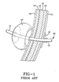
- a gastrostomy tube 10 which has been placed in a person for introducing a liquid nutritional product into the stomach of a person.
- the gastrostomy tube 10 extends through the epidermis 11, the fat layer 12, the muscle layer 13, the peritoneum 14, the stomach lining 15, and the gastric mucosa 16.
- One end 17 of the gastrostomy tube is located within the person's stomach.
- An expandable member 18 is located within the stomach, adjacent to the mucosa wall 16, and functions as an internal retaining member to reduce the chances of an unplanned removal of the gastrostomy tube from the person's stomach.
- An external retaining device 19 is located externally of the person adjacent to the epidermis 11.
- This particular external retaining device is a prior art disk shaped member which functions to maintain the gastrostomy tube substantially perpendicular to the person's skin.
- Such a prior art external retaining device is employed for example in gastrostomy tubes which have been distributed by Sandoz Nutrition Corporation, 5320 West Twenty Third Street, P.0. Box 370, Minneapolis, Minnesota 55440, U.S.A., under trade names such as CALUSO® PEG and SUPER PEGTM.
- the Sandoz enteral retaining device has a base portion that is round, other shapes such as a triangular device taught in the U.S. Patent 5,071,405 are of similar structure.
- the portion 20 of the feeding tube which is external of the person's body include: (a) unless the feeding tube is taped to the person's skin the tube can easily become tangled in the person's clothing or pulled by an incoherent person; (b) if the tube is taped to the persons's skin it must be shaped into a loop, which could kink the tube closed or at least reduce the effective cross-sectional area of the tube and restrict the flow of liquid through the tube; and (c) if a person should pull on the tube it will exert a force on the internal retaining device 18 perpendicular to the person's tissues and could result in an unintentional removal of the feeding tube from the stomach.
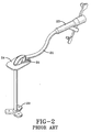
- a gastrostomy tube 21 having an internal retaining member 22 located near one end and a Y-port 23 near the other end for connecting the gastrostomy tube to a source of a liquid nutritional product.
- This particular feeding tube employs an external retaining device 24 which can be placed adjacent to a person's skin and directs the protruding tube back towards the person's skin.
- a ratcheted tie 25 secures the feeding tube 21 in an arcuate channel formed in the external retaining device.
- Such a prior art external retaining member has been marketed by Sandoz Nutrition as a component of a feeding tube product marketed under the trade name NUPORT® PEG.
- the problems encountered with this prior art external retaining device include: (a) any significant change in the person's weight could require an adjustment in the location along the tube of the external retaining device and in order to move the external retaining member the ratcheted tie must be severed and replaced, which requires maintaining a supply of the ratcheted ties; and (b) a patient that is not rational could pull on the ratcheted tie and interrupt the flow of nutritional product through the feeding tube, necessitating replacement of the ratcheted tie.
- a retaining device according to the preamble of claim 1 is knowm from US-A-4 645 492.
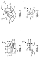
- FIG. 3 is a perspective view
- Fig. 5 is a top view
- Fig. 4 is a cross sectional view looking in the direction of the arrows of line 4-4 in Fig. 5
- Fig. 6 is an end view looking in the direction indicated by the arrows 6 in Fig. 3.
- the external retaining device sometimes referred to in the medical device trade as a skin disk, comprises a substantially flat base portion 31 having a tube guiding portion 34 extending from one side thereof.
- all terms such as “top”, “bottom”, “upper”, “lower”, “vertical” and “horizontal” when used with respect to the retaining device of the present invention are understood to refer to a retaining device resting on a flat horizontal surface with the tube guiding portion 34 extending upwardly from said flat horizontal surface.
- the external retaining device is a single molded piece, while it is recognized to be within the scope of the invention to make the base portion and tube guiding portions separately and thereafter join them together, for example with a suitable adhesive.
- the external retaining device is molded as a single piece from silicone rubber, polyvinyl chloride, or any other soft elastomeric material which is not an irritant to a person's skin.
- the base portion 31 is shown as being rectangular with rounded corners, it is understood that the base portion may be circular, triangular, or any desired shaped.
- the bottom surface of the base portion is shown as being substantially flat, as in Fig. 6, it is understood that the bottom surface could, if desired, be corrugated to allow the access of air to the underlying skin.
- an indent 38 in the underside of the tube guiding portion as best shown in Fig. 4, it is within the scope of the invention to eliminate the indent so that the device has a more solid and rigid structure.
- the base portion of the device has upper and lower surfaces which are parallel to one another, as shown in Figs. 3, 4 and 6, but it is within the scope of the invention to have either one or both of these surfaces curved.
- the base portion has at least one hole 32, 33 formed therein to facilitate suturing the external retaining device to a person's skin.
- the holes 32, 33 which are preferably formed during a molding process tend to reduce the tearing of the base portion when stresses are placed on the sutures.
- the external retaining device has a vertical hole 35 and a horizontal hole 36 formed therein, with a tube guiding channel 37 extending therebetween.
- the tube guiding channel has an external surface which is concave so as to be complementary to the external surface of a tube which is received in the channel.
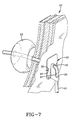
- the use of the external retaining device of the present invention may be better understood by referring to Fig. 7 in conjunction with Figs. 3-6.
- a gastrostomy tube 41 extends from outside of a person through several layers 42 of body tissue (which were described in greater detail above with respect to Fig. 1) into a person's stomach.
- An internal retaining member 43 which in this embodiment is a balloon which is well known in the art, is disposed adjacent to the mucosa of the stomach.
- the bottom side of the external retaining device is against the person's skin and is preferably secured thereto by one or more sutures 40 which extend through the holes 32, 33 formed in the base portion 31 of the external retaining device.
- the hole 35 (which is oriented vertically in Figs. 3-6) is aligned with the stoma through which the gastrostomy tube extends.
- the gastrostomy tube passes through the base portion of the external retaining device via the hole 35, then is disposed within the tube guiding channel 37, and then passes through a hole 36 (which is oriented horizontally in Figs. 3-6).
- the feeding tube passes through a first hole 35, then as guided through a 90° bend following a radius of curvature such that the tube is not kinked, and then passes through a second hole 36, with the longitudinal axes of the holes being coplanar and oriented perpendicular to one another.
- a feeding tube enters the external retaining device through a first hole 36 with extends substantially parallel to the person's skin, then is disposed within a channel 37 which guides the feeding tube in an unkinked condition through a 90° turn, then the feeding tube exits the external retaining device via a second hole 35 which is oriented substantially perpendicular to the person's skin and is aligned with the stoma.
- the channel 37 is of sufficient depth that it prevents the lateral movement of the portion of the feeding tube which is disposed therein.
- the diameters of the holes in the external retaining device is believed to be important to the proper functioning of the device.
- an external retaining device made of silicone rubber may be used with a size 6,67 mm (20 French) (6,68 mm; .263" outside diameter) silicone rubber feeding tube.
- the inside diameter of the hole 35 which will be perpendicular to the person's skin may be about 5,842 mm (.230") so that there is a very slight interference fit, while the inside diameter of the hole 36 which will be perpendicular to the person's skin may be about 7,112 mm (.280") so that there is no interference between the feeding tube and the external retaining device when the feeding tube passes through this hole.
- the relative sizes of the holes and feeding tube may be varied depending upon the materials of which they are made and the desires of the manufacturer and user.
- the external retaining device of the present invention therefore functions not only as a retaining device, but also as an anti-kinking device. Furthermore, the location of the external retaining device relative to the feeding tube can be adjusted without having to replace a ratcheted tie as in the prior art device shown in Fig. 2. Furthermore, there is no loop in the feeding tube for an incoherent person to pull on, as when the feeding tube of Fig. 1 is looped and taped to a person's skin.
- Yet another advantage of the external retaining device of the present invention is that if the portion of the feeding tube which extends externally of the person beyond the retaining device is pulled upon, the feeding tube does not slip easily through the external retaining device and the force exerted upon an internal retaining device 43 is not fully exerted in a direction parallel to the stoma, so that the likelihood of an unintentional removal of the feeding tube from the stomach is decreased.
- a gastrostomy tube 45 which passes through a person's tissues 42 (which were described in greater detail above with respect to Fig. 1) via a stoma to enter the stomach 46.
- This gastrostomy tube has an internal retaining member 47 which is of a different structure from the internal retaining member illustrated in Fig. 7.
- This gastrostomy tube has an internal retaining member 47 of the type taught in commonly owned U.S. Patent 5,080,650. That is to say, as best shown in Fig.
- the internal retaining element 47 is formed of an elastomeric material and comprises three resilient petaloid flanges 48 extended from a tubular hub 50, which has a bore 51 extending therethrough, with substantially triangular connecting portions 49 interposed between and connecting each pair of next adjacent petaloid flanges 48.
- the connecting portions 49 may be thinner than the petaloid flanges 48, as shown in Fig. 9, and may be formed of a different material from the petaloid flanges.
- an external retaining device 30, according to the present invention shown secured in place by sutures 40, may be used in conjunction with an internal retaining member which is either expandable or non-expandable. It is also to be noted in Fig.
- a feeding tube 45 assembly in accordance with the invention preferably includes means for connecting the feeding tube to a source of liquid nutrition, for example a Y-port 52.
- a source of liquid nutrition for example a Y-port 52.
- a Y-port is taught in commonly owned U.S. Design Patent 308,576, as well as in commonly owned U.S. Patent 5,057,093.
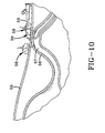
- Fig. 10 shows the use of the new external retaining member 30 in conjunction with a jejunostomy tube 59.
- the jejunostomy tube 59 passes through the abdominal wall 55, intestinal wall 56 and is located in the jejunum 57.
- the intestine is secured adjacent to the abdominal wall using T-Fastener assemblies 58, of the type taught in U.S. Patent RE 34,021.
- a jejunostomy tube has a much smaller diameter than a gastrostomy tube, and the dimensions of the external retaining device 30 of the present invention must be adjusted accordingly. It is to be noted from Fig. 10 that no internal retaining device is used in conjunction with the jejunostomy tube.
- the peristaltic action of the intestines may exert forces on the jejunostomy tube which tend to cause a portion of the tube to back-out of the body via the stoma.
- the interference fit between the tube and the external retaining device at the vertical hole in the external retaining device tends to minimize the amount of tube back-out, and tends to prevent the backed-out portion of the tube from kinking.
- an external retaining device solves several problems that were present in the prior art devices and that an assembly of the new external retaining device and a tube for enteral feeding has utility for feeding a person.
Landscapes
- Health & Medical Sciences (AREA)
- Life Sciences & Earth Sciences (AREA)
- Animal Behavior & Ethology (AREA)
- General Health & Medical Sciences (AREA)
- Public Health (AREA)
- Veterinary Medicine (AREA)
- Pulmonology (AREA)
- Anesthesiology (AREA)
- Biophysics (AREA)
- Engineering & Computer Science (AREA)
- Gastroenterology & Hepatology (AREA)
- Biomedical Technology (AREA)
- Heart & Thoracic Surgery (AREA)
- Hematology (AREA)
- Medical Preparation Storing Or Oral Administration Devices (AREA)
- Media Introduction/Drainage Providing Device (AREA)
- Guides For Winding Or Rewinding, Or Guides For Filamentary Materials (AREA)
- Rigid Pipes And Flexible Pipes (AREA)
- Basic Packing Technique (AREA)
- Supplying Of Containers To The Packaging Station (AREA)
- Orthopedics, Nursing, And Contraception (AREA)
- Clamps And Clips (AREA)
Claims (8)
- Externe Haltevorrichtung (30) zur Verwendung mit einem Ernährungsschlauch (41), der einen Grundabschnitt (31) und einen Schlauchführungsabschnitt (34) umfaßt, der sich nach oben vom Grundabschnitt (31) erstreckt, wobei der Grundabschnitt (31) und der Schlauchführungsabschnitt (34) ein sich dadurch senkrecht erstreckendes Loch (35) aufweisen, wobei der Schlauchführungsabschnitt (34) ein sich dadurch horizontal erstreckendes Loch (36) aufweist, wobei die senkrechten und horizontalen Löcher (35, 36) Längsachsen aufweisen, die koplanar und zueinander rechtwinklig ausgerichtet sind, wobei die senkrechten und horizontalen Löcher (35, 36) durch einen sich zwischen den Löchern (35, 36) erstreckenden Schlauchführungskanal (37) im Schlauchführungsabschnitt (34) miteinander kommunizieren, wobei der Schlauchführungskanal (37) eine mittlere Achse hat, die sich koplanar zur Längsachse der Löcher (35, 36) derart erstreckt, daß ein ununterbrochenes Schlauchglied durch beide Löcher (35, 36) passieren kann und im Schlauchführungskanal (37) aufliegen kann, wobei die Längsachse des Schlauchgliedes in der gleichen Ebene liegt wie die Längsachsen der Löcher (35, 36), dadurch gekennzeichnet, daß der Schlauchkanal (37) aus einem exponierten konkaven Schlauchführungskanal besteht.
- Externe Haltevorrichtung (30) zur Verwendung mit einem Ernährungsschlauch (41) gemäß Anspruch 1, wobei der Grundabschnitt (31) mindestens ein zusätzliches Loch (32, 33) aufweist, das darin gebildet wird, um das Annähen der externen Haltevorrichtung (30) an eine Person zu ermöglichen.
- Externe Haltevorrichtung (30) zur Verwendung mit einem Ernährungsschlauch (41) gemäß den Ansprüchen 1 oder 2, wobei der innere Durchmesser des sich senkrecht erstreckenden Loches (35) kleiner ist als der innere Durchmesser des sich horizontal erstreckenden Loches (36).
- Externe Haltevorrichtung (30) zur Verwendung mit einem Ernährungsschlauch (41) gemäß einem oder mehreren der Ansprüche 1 bis 3, wobei der exponierte konkave Schlauchführungskanal (37) eine äußere Oberfläche hat, die konkav ist, um komplementär zur äußeren Oberfläche eines Schlauches (41) zu sein, der im exponierten konkaven Führungskanal (37) aufgenommen wird.
- Zusammenbau eines enteralen Ernährungsschlauchs (41) und einer externen Haltevorrichtung (30) gemäß einem oder mehreren der Ansprüche 1 bis 4, wobei der enterale Ernährungsschlauch (41) ein hohles schlauchartiges Glied umfaßt, das erste und zweite Enden hat, wobei das schlauchartige Glied innerhalb des exponierten konkaven Schlauchführungskanals (37) angeordnet ist und sich sowohl durch die senkrechten als auch durch die horizontalen Löcher (35, 36) erstreckt.
- Zusammenbau eines enteralen Ernährungsschlauchs (41) und einer externen Haltevorrichtung (30) gemäß Anspruch 5, wobei der Ernährungsschlauch (41) ein Gastrostomieschlauch ist und weiterhin eine interne Haltevorrichtung (43, 47) enthält.
- Zusammenbau eines enteralen Ernährungsschlauchs (41) und einer externen Haltevorrichtung (30) gemäß Anspruch 6, wobei die interne Haltevorrichtung (43, 47) ausdehnbar ist.
- Zusammenbau eines enteralen Ernährungsschlauchs (41) und einer externen Haltevorrichtung (30) gemäß Anspruch 5, wobei der Ernährungsschlauch (41) ein Jejunostomieschlauch ist.
Applications Claiming Priority (3)
| Application Number | Priority Date | Filing Date | Title |
|---|---|---|---|
| US07/958,374 US5267969A (en) | 1992-10-08 | 1992-10-08 | External retaining device for feeding tube or the like |
| US958374 | 1992-10-08 | ||
| PCT/US1993/006753 WO1994008648A1 (en) | 1992-10-08 | 1993-07-19 | External retaining device for a feeding tube |
Publications (3)
| Publication Number | Publication Date |
|---|---|
| EP0746357A4 EP0746357A4 (de) | 1995-08-28 |
| EP0746357A1 EP0746357A1 (de) | 1996-12-11 |
| EP0746357B1 true EP0746357B1 (de) | 2001-05-30 |
Family
ID=25500893
Family Applications (1)
| Application Number | Title | Priority Date | Filing Date |
|---|---|---|---|
| EP93917263A Expired - Lifetime EP0746357B1 (de) | 1992-10-08 | 1993-07-19 | Externe haltevorrichtung für einen ernährungsschlauch |
Country Status (8)
| Country | Link |
|---|---|
| US (1) | US5267969A (de) |
| EP (1) | EP0746357B1 (de) |
| JP (1) | JP2718831B2 (de) |
| AU (1) | AU675962B2 (de) |
| CA (1) | CA2143119C (de) |
| DE (1) | DE69330289T2 (de) |
| ES (1) | ES2158862T3 (de) |
| WO (1) | WO1994008648A1 (de) |
Cited By (2)
| Publication number | Priority date | Publication date | Assignee | Title |
|---|---|---|---|---|
| DE102012104463A1 (de) * | 2012-05-23 | 2013-11-28 | B. Braun Avitum Ag | Schlauchführungselement; medizinisches Gerät zur extrakorporalen Blutbehandlung mit Schlauchführungselement |
| EP4688079A4 (de) * | 2023-03-31 | 2026-07-08 | Forcast Orthopedics Inc | Tragbare medizinische vorrichtung |
Families Citing this family (60)
| Publication number | Priority date | Publication date | Assignee | Title |
|---|---|---|---|---|
| US5653718A (en) * | 1994-05-16 | 1997-08-05 | Yoon; Inbae | Cannula anchoring system |
| US5540648A (en) * | 1992-08-17 | 1996-07-30 | Yoon; Inbae | Medical instrument stabilizer with anchoring system and methods |
| NL9301810A (nl) * | 1993-10-19 | 1995-05-16 | Nutricia Nv | Beugel voor verbindingsinrichting. |
| US5451212A (en) * | 1994-01-21 | 1995-09-19 | Corpak, Inc. | Bumper retention device |
| USD379854S (en) * | 1994-02-04 | 1997-06-10 | Abbott Laboratories | Feeding tube |
| US5556385A (en) * | 1994-12-06 | 1996-09-17 | Corpak, Inc. | Improved percutaneous access device |
| US5738661A (en) * | 1995-06-16 | 1998-04-14 | Larice; Gennaro | Medical device for holding a feeding tube and use thereof |
| DE19533749A1 (de) * | 1995-09-12 | 1997-03-13 | Fresenius Ag | Stoma-Gastrostomiesonde mit flacher Rückhalteplatte und optionaler variabler Schaftlänge |
| US6066112A (en) * | 1996-01-11 | 2000-05-23 | Radius International Limited Partnership | Corporeal access tube assembly and method |
| ES2236435T3 (es) * | 1996-01-11 | 2005-07-16 | C.R. Bard Inc. | Cabezal de retencion para conjunto de tubo para acceder al cuerpo. |
| US6077243A (en) * | 1996-01-11 | 2000-06-20 | C.R. Bard, Inc. | Retention balloon for a corporeal access tube assembly |
| US6036673A (en) * | 1996-01-11 | 2000-03-14 | C. R. Bard, Inc. | Bolster for corporeal access tube assembly |
| US5860952A (en) * | 1996-01-11 | 1999-01-19 | C. R. Bard, Inc. | Corporeal access tube assembly and method |
| US5741235A (en) * | 1996-10-29 | 1998-04-21 | Knight; John R. | Retention device for medical drainage tubes and billary stents |
| US5941855A (en) * | 1997-10-03 | 1999-08-24 | Applied Medical Technology, Inc. | Gastrostomy device package and method of assembly |
| DE19749741C1 (de) | 1997-11-11 | 1998-11-05 | Medi Globe Gip Medizin Technik | Fixiervorrichtung zur Befestigung eines percutan verlegten Schlauchs |
| US6364858B1 (en) | 1998-03-31 | 2002-04-02 | Applied Medical Research, Inc. | Collapsible internal bolster for gastrostomy device |
| US6231547B1 (en) | 1999-02-18 | 2001-05-15 | Abbott Laboratories | External retaining device for a catheter and catheter assembly and method using same |
| US6471676B1 (en) | 2000-03-21 | 2002-10-29 | Novartis Nutrition Ag | Catheter and feeding tube retention device and method of use |
| US6482183B1 (en) * | 2000-05-10 | 2002-11-19 | Gudrun Pausch | Apparatus for the fixation of a percutaneous flexible line |
| US6511474B1 (en) | 2000-07-12 | 2003-01-28 | Corpak, Inc. | Bolus for non-occluding high flow enteral feeding tube |
| DE10055283B4 (de) * | 2000-11-08 | 2004-07-15 | Fresenius Kabi Deutschland Gmbh | Adapter für eine PEG-Sonde |
| DE10055281B4 (de) * | 2000-11-08 | 2004-12-23 | Fresenius Kabi Deutschland Gmbh | Adapter für eine PEG-Sonde |
| US20050187524A1 (en) * | 2000-12-19 | 2005-08-25 | Willis Allan F. | Sealing valve assembly for medical products |
| US6767340B2 (en) | 2000-12-19 | 2004-07-27 | Kimberly-Clark Worldwide, Inc. | Sealing valve assembly for medical products |
| US6908449B2 (en) * | 2000-12-19 | 2005-06-21 | Kimberly-Clark Worldwide, Inc. | Sealing valve assembly for medical products |
| US20030199831A1 (en) * | 2002-04-23 | 2003-10-23 | Morris Mary M. | Catheter anchor system and method |
| US20030225369A1 (en) * | 2002-05-31 | 2003-12-04 | Kimberly-Clark Worldwide, Inc. | Low profile transpyloric jejunostomy system |
| US20030225392A1 (en) * | 2002-05-31 | 2003-12-04 | Kimberly-Clark Worldwide, Inc. | Low profile transpyloric jejunostomy system and method to enable |
| US20040103987A1 (en) * | 2002-11-30 | 2004-06-03 | Triebes Thomas Gregory | Process for producing unitary component and a catheter having a unitary component |
| US20040106899A1 (en) * | 2002-11-30 | 2004-06-03 | Mcmichael Donald J. | Gastric balloon catheter with improved balloon orientation |
| US7534224B2 (en) | 2002-11-30 | 2009-05-19 | Kimberly-Clark Worldwide, Inc. | Catheter with unitary component |
| US7124489B2 (en) * | 2002-11-30 | 2006-10-24 | Kimberly-Clark Worldwide, Inc. | Process for producing a catheter |
| US20040106901A1 (en) * | 2002-11-30 | 2004-06-03 | Letson William W. | Catheter having a balloon member invertedly attached thereto |
| US7976518B2 (en) | 2005-01-13 | 2011-07-12 | Corpak Medsystems, Inc. | Tubing assembly and signal generator placement control device and method for use with catheter guidance systems |
| US7985205B2 (en) | 2005-09-14 | 2011-07-26 | Boston Scientific Scimed, Inc. | Medical catheter external bolster having strain relief member |
| WO2008042627A1 (en) * | 2006-09-28 | 2008-04-10 | Cook Critical Care Incorporated | Bolster assembly |
| USD561329S1 (en) | 2006-10-04 | 2008-02-05 | Kimberly-Clark Worldwide, Inc. | Low profile transpyloric jejunostomy catheter |
| US20080243082A1 (en) * | 2007-03-30 | 2008-10-02 | Closure Medical Corporation | System for surgical drain fixation |
| US20090318897A1 (en) * | 2008-06-20 | 2009-12-24 | Cook Critical Care Incorporated | Gastrojejunal feeding assembly |
| US9107810B2 (en) * | 2008-06-24 | 2015-08-18 | Cook Medical Technologies Llc | Gastric port system |
| JP2010158486A (ja) * | 2009-01-09 | 2010-07-22 | Kaneka Corp | 胃瘻カテーテル |
| JP5567323B2 (ja) * | 2009-12-07 | 2014-08-06 | 株式会社カネカ | 瘻カテーテル |
| EP2512583B1 (de) * | 2009-12-15 | 2025-04-23 | Board of Regents of the University of Nebraska | Hülle |
| US8522800B2 (en) * | 2009-12-29 | 2013-09-03 | Rob Parker | Tile cleanup apparatus |
| WO2012103123A2 (en) | 2011-01-28 | 2012-08-02 | Medtronic, Inc. | Repositionable therapy delivery element anchor |
| US9028441B2 (en) | 2011-09-08 | 2015-05-12 | Corpak Medsystems, Inc. | Apparatus and method used with guidance system for feeding and suctioning |
| WO2015103094A1 (en) * | 2013-12-30 | 2015-07-09 | H. Lee Moffitt Cancer Center And Research Institute, Inc. | Locking brakes for enteral feeding tube retention member |
| KR101587015B1 (ko) | 2015-08-06 | 2016-01-21 | 주식회사 에스엠허스 | 카테터 고정구 |
| US10690655B2 (en) | 2016-02-18 | 2020-06-23 | Ur24 Technology, Llc | Automated urine collector-analyzer |
| US10682124B2 (en) | 2016-02-18 | 2020-06-16 | Ur24 Technology, Llc | Automated collection and analysis of body fluids |
| JP6839452B2 (ja) | 2016-02-18 | 2021-03-10 | ユーアール24 テクノロジー,エルエルシー | 自動尿採取器−分析器 |
| EP3500328A4 (de) | 2016-08-19 | 2020-08-12 | Levity Products, Inc. | Externer katheterstabilisator |
| USD876621S1 (en) | 2017-08-18 | 2020-02-25 | Sarah L. Olson | External catheter stabilizer |
| MX2021007545A (es) | 2018-12-21 | 2021-08-11 | Levity Products Inc | Estabilizador de cateter externo. |
| US11311405B2 (en) | 2020-05-22 | 2022-04-26 | Ur24Technology, Inc. | Methods and apparatus for collecting body fluids |
| USD969308S1 (en) | 2020-05-28 | 2022-11-08 | Ur24Technology, Inc. | Fluid collection apparatus |
| WO2022224175A1 (en) * | 2021-04-22 | 2022-10-27 | The Insides Company Limited | Improved feeding catheter |
| USD1034967S1 (en) | 2022-10-31 | 2024-07-09 | Ur24Technology, Inc. | Fluid collection apparatus |
| USD1034968S1 (en) | 2022-10-31 | 2024-07-09 | Ur24Technology, Inc. | Fluid collection apparatus |
Family Cites Families (13)
| Publication number | Priority date | Publication date | Assignee | Title |
|---|---|---|---|---|
| US3568679A (en) * | 1968-11-12 | 1971-03-09 | Dow Corning | Catheter placement unit |
| US4261363A (en) * | 1979-11-09 | 1981-04-14 | C. R. Bard, Inc. | Retention clips for body fluid drains |
| US4419094A (en) * | 1981-06-08 | 1983-12-06 | The Kendall Company | Suprapubic catheter system |
| GB2115290A (en) | 1982-02-18 | 1983-09-07 | Clive Ian Pratt | Medical cannula location device |
| US4435174A (en) * | 1982-04-12 | 1984-03-06 | American Hospital Supply Corporation | Catheter guide |
| US4533349A (en) * | 1982-11-08 | 1985-08-06 | Medical Engineering Corporation | Skin mounted drainage catheter retention disc |
| US4645492A (en) * | 1983-10-11 | 1987-02-24 | Medical Engineering Corporation | Catheter anchoring device |
| US4666433A (en) * | 1984-11-05 | 1987-05-19 | Medical Innovations Corporation | Gastrostomy feeding device |
| US4717385A (en) * | 1985-04-12 | 1988-01-05 | The Beth Israel Hospital Association | Surgical tube anchoring device and method for using same |
| US4886508A (en) * | 1988-07-11 | 1989-12-12 | Washington Douglas L | Ladies external catheter assembly |
| US5073166A (en) * | 1989-02-15 | 1991-12-17 | Medical Innovations Corporation | Method and apparatus for emplacement of a gastrostomy catheter |
| US5084024A (en) * | 1989-12-07 | 1992-01-28 | Thermedics, Inc. | Catheter and method for relieving catheter stress |
| US5147320A (en) * | 1991-05-03 | 1992-09-15 | Sorex Medical, Inc. | Catheter affixing and anchoring pad and method of use |
-
1992
- 1992-10-08 US US07/958,374 patent/US5267969A/en not_active Expired - Lifetime
-
1993
- 1993-07-19 DE DE69330289T patent/DE69330289T2/de not_active Expired - Fee Related
- 1993-07-19 CA CA002143119A patent/CA2143119C/en not_active Expired - Fee Related
- 1993-07-19 JP JP6509966A patent/JP2718831B2/ja not_active Expired - Fee Related
- 1993-07-19 AU AU46832/93A patent/AU675962B2/en not_active Ceased
- 1993-07-19 WO PCT/US1993/006753 patent/WO1994008648A1/en not_active Ceased
- 1993-07-19 ES ES93917263T patent/ES2158862T3/es not_active Expired - Lifetime
- 1993-07-19 EP EP93917263A patent/EP0746357B1/de not_active Expired - Lifetime
Cited By (2)
| Publication number | Priority date | Publication date | Assignee | Title |
|---|---|---|---|---|
| DE102012104463A1 (de) * | 2012-05-23 | 2013-11-28 | B. Braun Avitum Ag | Schlauchführungselement; medizinisches Gerät zur extrakorporalen Blutbehandlung mit Schlauchführungselement |
| EP4688079A4 (de) * | 2023-03-31 | 2026-07-08 | Forcast Orthopedics Inc | Tragbare medizinische vorrichtung |
Also Published As
| Publication number | Publication date |
|---|---|
| EP0746357A1 (de) | 1996-12-11 |
| AU675962B2 (en) | 1997-02-27 |
| US5267969A (en) | 1993-12-07 |
| EP0746357A4 (de) | 1995-08-28 |
| ES2158862T3 (es) | 2001-09-16 |
| CA2143119C (en) | 1999-02-16 |
| DE69330289D1 (de) | 2001-07-05 |
| DE69330289T2 (de) | 2002-03-14 |
| WO1994008648A1 (en) | 1994-04-28 |
| JP2718831B2 (ja) | 1998-02-25 |
| JPH07506994A (ja) | 1995-08-03 |
| CA2143119A1 (en) | 1994-04-28 |
| AU4683293A (en) | 1994-05-09 |
Similar Documents
| Publication | Publication Date | Title |
|---|---|---|
| US5267969A (en) | External retaining device for feeding tube or the like | |
| EP1152789B1 (de) | Äusserliche befestigungsvorrichtung für einen katheter | |
| EP0182539B1 (de) | Gastrojejunal-Fütterungsgerät | |
| US6471676B1 (en) | Catheter and feeding tube retention device and method of use | |
| US4685901A (en) | Gastro-jejunal feeding device | |
| AU683724B2 (en) | Gastrostomy tube with improved internal retaining member | |
| US4798592A (en) | Gastrostomy feeding device | |
| EP1077057B1 (de) | Ausgleichsstück für ein enterales Ernährungssystem | |
| CA2059790C (en) | Gastrostomy tube | |
| US4778448A (en) | Naso-enteral tube harness apparatus and method | |
| JP3347148B2 (ja) | 瘻形成装置 | |
| US6036673A (en) | Bolster for corporeal access tube assembly | |
| EP1603626A1 (de) | Katheter mit einer einstellbaren orthese | |
| JPS61159971A (ja) | 胃造瘻術カテーテル | |
| KR20080010398A (ko) | 체내 유치 장치 | |
| US4972845A (en) | Stoma measuring device | |
| MXPA01008366A (en) | External retaining device for a catheter and catheter assembly and method using same |
Legal Events
| Date | Code | Title | Description |
|---|---|---|---|
| A4 | Supplementary search report drawn up and despatched | ||
| AK | Designated contracting states |
Kind code of ref document: A4 Designated state(s): DE ES FR GB IE IT NL |
|
| PUAI | Public reference made under article 153(3) epc to a published international application that has entered the european phase |
Free format text: ORIGINAL CODE: 0009012 |
|
| 17P | Request for examination filed |
Effective date: 19950418 |
|
| AK | Designated contracting states |
Kind code of ref document: A1 Designated state(s): DE ES FR GB IE IT NL |
|
| 17Q | First examination report despatched |
Effective date: 19990316 |
|
| GRAG | Despatch of communication of intention to grant |
Free format text: ORIGINAL CODE: EPIDOS AGRA |
|
| GRAG | Despatch of communication of intention to grant |
Free format text: ORIGINAL CODE: EPIDOS AGRA |
|
| GRAH | Despatch of communication of intention to grant a patent |
Free format text: ORIGINAL CODE: EPIDOS IGRA |
|
| GRAH | Despatch of communication of intention to grant a patent |
Free format text: ORIGINAL CODE: EPIDOS IGRA |
|
| GRAA | (expected) grant |
Free format text: ORIGINAL CODE: 0009210 |
|
| AK | Designated contracting states |
Kind code of ref document: B1 Designated state(s): DE ES FR GB IE IT NL |
|
| REF | Corresponds to: |
Ref document number: 69330289 Country of ref document: DE Date of ref document: 20010705 |
|
| REG | Reference to a national code |
Ref country code: IE Ref legal event code: FG4D |
|
| ITF | It: translation for a ep patent filed | ||
| REG | Reference to a national code |
Ref country code: ES Ref legal event code: FG2A Ref document number: 2158862 Country of ref document: ES Kind code of ref document: T3 |
|
| ET | Fr: translation filed | ||
| REG | Reference to a national code |
Ref country code: GB Ref legal event code: IF02 |
|
| PLBE | No opposition filed within time limit |
Free format text: ORIGINAL CODE: 0009261 |
|
| STAA | Information on the status of an ep patent application or granted ep patent |
Free format text: STATUS: NO OPPOSITION FILED WITHIN TIME LIMIT |
|
| 26N | No opposition filed | ||
| PGFP | Annual fee paid to national office [announced via postgrant information from national office to epo] |
Ref country code: GB Payment date: 20050614 Year of fee payment: 13 |
|
| PGFP | Annual fee paid to national office [announced via postgrant information from national office to epo] |
Ref country code: NL Payment date: 20050616 Year of fee payment: 13 |
|
| PGFP | Annual fee paid to national office [announced via postgrant information from national office to epo] |
Ref country code: IE Payment date: 20050630 Year of fee payment: 13 |
|
| PGFP | Annual fee paid to national office [announced via postgrant information from national office to epo] |
Ref country code: FR Payment date: 20050706 Year of fee payment: 13 |
|
| PGFP | Annual fee paid to national office [announced via postgrant information from national office to epo] |
Ref country code: ES Payment date: 20050712 Year of fee payment: 13 |
|
| PGFP | Annual fee paid to national office [announced via postgrant information from national office to epo] |
Ref country code: DE Payment date: 20050729 Year of fee payment: 13 |
|
| PG25 | Lapsed in a contracting state [announced via postgrant information from national office to epo] |
Ref country code: IE Free format text: LAPSE BECAUSE OF NON-PAYMENT OF DUE FEES Effective date: 20060719 Ref country code: GB Free format text: LAPSE BECAUSE OF NON-PAYMENT OF DUE FEES Effective date: 20060719 |
|
| PGFP | Annual fee paid to national office [announced via postgrant information from national office to epo] |
Ref country code: IT Payment date: 20060731 Year of fee payment: 14 |
|
| PG25 | Lapsed in a contracting state [announced via postgrant information from national office to epo] |
Ref country code: NL Free format text: LAPSE BECAUSE OF NON-PAYMENT OF DUE FEES Effective date: 20070201 Ref country code: DE Free format text: LAPSE BECAUSE OF NON-PAYMENT OF DUE FEES Effective date: 20070201 |
|
| GBPC | Gb: european patent ceased through non-payment of renewal fee |
Effective date: 20060719 |
|
| NLV4 | Nl: lapsed or anulled due to non-payment of the annual fee |
Effective date: 20070201 |
|
| REG | Reference to a national code |
Ref country code: IE Ref legal event code: MM4A |
|
| REG | Reference to a national code |
Ref country code: FR Ref legal event code: ST Effective date: 20070330 |
|
| REG | Reference to a national code |
Ref country code: ES Ref legal event code: FD2A Effective date: 20060720 |
|
| PG25 | Lapsed in a contracting state [announced via postgrant information from national office to epo] |
Ref country code: ES Free format text: LAPSE BECAUSE OF NON-PAYMENT OF DUE FEES Effective date: 20060720 |
|
| PG25 | Lapsed in a contracting state [announced via postgrant information from national office to epo] |
Ref country code: FR Free format text: LAPSE BECAUSE OF NON-PAYMENT OF DUE FEES Effective date: 20060731 |
|
| PG25 | Lapsed in a contracting state [announced via postgrant information from national office to epo] |
Ref country code: IT Free format text: LAPSE BECAUSE OF NON-PAYMENT OF DUE FEES Effective date: 20070719 |