EP0746348B1 - Dichtung für alle durchmesserbereiche chirurgischer instrumente - Google Patents
Dichtung für alle durchmesserbereiche chirurgischer instrumente Download PDFInfo
- Publication number
- EP0746348B1 EP0746348B1 EP94910686A EP94910686A EP0746348B1 EP 0746348 B1 EP0746348 B1 EP 0746348B1 EP 94910686 A EP94910686 A EP 94910686A EP 94910686 A EP94910686 A EP 94910686A EP 0746348 B1 EP0746348 B1 EP 0746348B1
- Authority
- EP
- European Patent Office
- Prior art keywords
- seal
- instrument
- annulus
- rigid
- laterally
- Prior art date
- Legal status (The legal status is an assumption and is not a legal conclusion. Google has not performed a legal analysis and makes no representation as to the accuracy of the status listed.)
- Expired - Lifetime
Links
Images


Classifications
-
- A—HUMAN NECESSITIES
- A61—MEDICAL OR VETERINARY SCIENCE; HYGIENE
- A61M—DEVICES FOR INTRODUCING MEDIA INTO, OR ONTO, THE BODY; DEVICES FOR TRANSDUCING BODY MEDIA OR FOR TAKING MEDIA FROM THE BODY; DEVICES FOR PRODUCING OR ENDING SLEEP OR STUPOR
- A61M39/00—Tubes, tube connectors, tube couplings, valves, access sites or the like, specially adapted for medical use
- A61M39/02—Access sites
- A61M39/06—Haemostasis valves, i.e. gaskets sealing around a needle, catheter or the like, closing on removal thereof
- A61M39/0613—Haemostasis valves, i.e. gaskets sealing around a needle, catheter or the like, closing on removal thereof with means for adjusting the seal opening or pressure
-
- A—HUMAN NECESSITIES
- A61—MEDICAL OR VETERINARY SCIENCE; HYGIENE
- A61B—DIAGNOSIS; SURGERY; IDENTIFICATION
- A61B17/00—Surgical instruments, devices or methods
- A61B17/34—Trocars; Puncturing needles
- A61B17/3462—Trocars; Puncturing needles with means for changing the diameter or the orientation of the entrance port of the cannula, e.g. for use with different-sized instruments, reduction ports, adapter seals
-
- A—HUMAN NECESSITIES
- A61—MEDICAL OR VETERINARY SCIENCE; HYGIENE
- A61M—DEVICES FOR INTRODUCING MEDIA INTO, OR ONTO, THE BODY; DEVICES FOR TRANSDUCING BODY MEDIA OR FOR TAKING MEDIA FROM THE BODY; DEVICES FOR PRODUCING OR ENDING SLEEP OR STUPOR
- A61M39/00—Tubes, tube connectors, tube couplings, valves, access sites or the like, specially adapted for medical use
- A61M39/02—Access sites
- A61M39/06—Haemostasis valves, i.e. gaskets sealing around a needle, catheter or the like, closing on removal thereof
-
- A—HUMAN NECESSITIES
- A61—MEDICAL OR VETERINARY SCIENCE; HYGIENE
- A61B—DIAGNOSIS; SURGERY; IDENTIFICATION
- A61B17/00—Surgical instruments, devices or methods
- A61B17/34—Trocars; Puncturing needles
- A61B17/3498—Valves therefor, e.g. flapper valves, slide valves
-
- A—HUMAN NECESSITIES
- A61—MEDICAL OR VETERINARY SCIENCE; HYGIENE
- A61B—DIAGNOSIS; SURGERY; IDENTIFICATION
- A61B17/00—Surgical instruments, devices or methods
- A61B17/34—Trocars; Puncturing needles
- A61B17/3462—Trocars; Puncturing needles with means for changing the diameter or the orientation of the entrance port of the cannula, e.g. for use with different-sized instruments, reduction ports, adapter seals
- A61B2017/3464—Trocars; Puncturing needles with means for changing the diameter or the orientation of the entrance port of the cannula, e.g. for use with different-sized instruments, reduction ports, adapter seals with means acting on inner surface of valve or seal for expanding or protecting, e.g. inner pivoting fingers
-
- A—HUMAN NECESSITIES
- A61—MEDICAL OR VETERINARY SCIENCE; HYGIENE
- A61M—DEVICES FOR INTRODUCING MEDIA INTO, OR ONTO, THE BODY; DEVICES FOR TRANSDUCING BODY MEDIA OR FOR TAKING MEDIA FROM THE BODY; DEVICES FOR PRODUCING OR ENDING SLEEP OR STUPOR
- A61M39/00—Tubes, tube connectors, tube couplings, valves, access sites or the like, specially adapted for medical use
- A61M39/02—Access sites
- A61M39/0247—Semi-permanent or permanent transcutaneous or percutaneous access sites to the inside of the body
- A61M2039/0279—Semi-permanent or permanent transcutaneous or percutaneous access sites to the inside of the body for introducing medical instruments into the body, e.g. endoscope, surgical tools
-
- A—HUMAN NECESSITIES
- A61—MEDICAL OR VETERINARY SCIENCE; HYGIENE
- A61M—DEVICES FOR INTRODUCING MEDIA INTO, OR ONTO, THE BODY; DEVICES FOR TRANSDUCING BODY MEDIA OR FOR TAKING MEDIA FROM THE BODY; DEVICES FOR PRODUCING OR ENDING SLEEP OR STUPOR
- A61M39/00—Tubes, tube connectors, tube couplings, valves, access sites or the like, specially adapted for medical use
- A61M39/02—Access sites
- A61M39/06—Haemostasis valves, i.e. gaskets sealing around a needle, catheter or the like, closing on removal thereof
- A61M2039/0626—Haemostasis valves, i.e. gaskets sealing around a needle, catheter or the like, closing on removal thereof used with other surgical instruments, e.g. endoscope, trocar
-
- A—HUMAN NECESSITIES
- A61—MEDICAL OR VETERINARY SCIENCE; HYGIENE
- A61M—DEVICES FOR INTRODUCING MEDIA INTO, OR ONTO, THE BODY; DEVICES FOR TRANSDUCING BODY MEDIA OR FOR TAKING MEDIA FROM THE BODY; DEVICES FOR PRODUCING OR ENDING SLEEP OR STUPOR
- A61M39/00—Tubes, tube connectors, tube couplings, valves, access sites or the like, specially adapted for medical use
- A61M39/02—Access sites
- A61M39/06—Haemostasis valves, i.e. gaskets sealing around a needle, catheter or the like, closing on removal thereof
- A61M2039/0673—Haemostasis valves, i.e. gaskets sealing around a needle, catheter or the like, closing on removal thereof comprising means actively pressing on the device passing through the seal, e.g. inflatable seals, diaphragms, clamps
-
- A—HUMAN NECESSITIES
- A61—MEDICAL OR VETERINARY SCIENCE; HYGIENE
- A61M—DEVICES FOR INTRODUCING MEDIA INTO, OR ONTO, THE BODY; DEVICES FOR TRANSDUCING BODY MEDIA OR FOR TAKING MEDIA FROM THE BODY; DEVICES FOR PRODUCING OR ENDING SLEEP OR STUPOR
- A61M39/00—Tubes, tube connectors, tube couplings, valves, access sites or the like, specially adapted for medical use
- A61M39/02—Access sites
- A61M39/06—Haemostasis valves, i.e. gaskets sealing around a needle, catheter or the like, closing on removal thereof
- A61M2039/0686—Haemostasis valves, i.e. gaskets sealing around a needle, catheter or the like, closing on removal thereof comprising more than one seal
Definitions
- the invention relates to a gas-tight seal for use in a surgical instrument to provide a gas-tight seal with an instrument passed through the seal.
- the seal can form a gas-tight seal with instruments having a wide range of diameters.
- Trocar tubes used in laparoscopic surgery are normally fitted with a gas-tight seal to maintain pneumoperitoneum when a laparoscopic instrument is inserted into the trocar tube.
- the gas-tight seal is normally built into the rear housing attached to the cannula of the trocar tube, and forms a gas-tight seal with an instrument having an outside diameter that is similar to the internal diameter of the cannula.
- the instrument port must be smaller than the diameter of the instrument so that the instrument can deform the elastic material surrounding the instrument port to form the seal with the instrument. Consequently, when the seal is to accommodate a range of instrument diameters, the instrument port must be smaller than the minimum of the range of instrument diameters for which the seal is designed, so that a minimum-diameter instrument can deform the elastic material. Deforming the elastic material results in a radial force between the elastic material and the instrument. This holds the elastic material in contact with the instrument and maintains the gas-tight seal.
- An instrument port diameter that produces the required amount of radial force for a minimum-diameter instrument results in a greater radial force when a larger-diameter instrument is inserted.
- the greater radial force increases friction between the seal and the instrument.
- the maximum of the diameter range, above which friction is so great as to make it impossible to manipulate the instrument may not be a great deal larger than the minimum of the diameter range, below which the gas-tight seal leaks.
- the radial force between the elastic material and the instrument at the minimum of the diameter range must be increased if the instrument is to be allowed to move laterally in the seal.
- the increased radial force is required to keep the elastic material remote from the direction of lateral displacement in contact with the instrument, and thus to maintain the gas-tight seal.
- This increase in the radial force further increases friction between the seal and the larger-diameter instrument, and thus further limits the diameter range that the seal will accommodate.
- a trocar tube with an auxiliary gas-tight seal.
- the auxiliary gas-tight seal supplements the diameter range capability of the main gas-tight seal.
- the patentee sells trocar assemblies in which the trocar tube has a 10 mm (0.4") diameter cannula that can accommodate instruments ranging from 5 mm (0.2") and 10 mm (0.4") in diameter.
- the trocar tube accommodates this range of diameters by providing two auxiliary door-type gas-tight seals in addition to the main gas-tight seal.
- the main gas-tight seal which will be described further below, seals with instruments between 9 and 10 mm in diameter; a first auxiliary seal seals with instruments 7 to 8 mm in diameter, and a second auxiliary seal seals with instruments 5 and 6 mm in diameter.
- the two auxiliary door-type gas-tight seals are stored on opposite sides of the rear housing of the trocar tube.
- Each auxiliary seal is mounted in a track that runs up the side and across the rear face of the housing.
- the surgeon must slide the appropriate auxiliary gas-tight seal up the track from the storage position into place on the proximal face of the housing.
- the auxiliary seal forms a seal with a lip on the main gas-tight seal, and seals with the smaller-diameter instrument passed through it. If another instrument with a different diameter is later to be inserted into the cannula, the one auxiliary seal must be returned to its storage position, and, if necessary, the other auxiliary seal deployed.
- United States Patent No. 5,104,383 describes a completely detachable auxiliary seal that allows an instrument as small as 5 mm in diameter to be used in a 10 mm cannula.
- the auxiliary seal is installed into the rear of the housing before a smaller-diameter instrument is inserted into the cannula.
- a single auxiliary gas-tight seal is made to accommodate instruments with a range of diameters by including a rigid stabilizer plate to prevent the instrument from being moved laterally relative to the cannula. The stabilizer plate keeps the instrument centered in the cannula, and prevents gas leaks caused by the instrument going off center in the auxiliary seal.
- auxiliary gas-tight seals either a single, wider range, auxiliary gas-tight seal or plural, narrower-range, auxiliary gas-tight seals can be used to accommodate instruments with a range of diameters. If plural, narrower-range, auxiliary gas-tight seals are used, the surgeon has to ensure that the auxiliary gas-tight seal is the appropriate one for the diameter of the instrument being used. If a single, wider-range auxiliary gas-tight seal is used, the surgeon must accept that the range of lateral movement of the instrument in the cannula is limited if the auxiliary gas-tight seal is to seal effectively with an instrument at the minimum of the diameter range.
- the instrument seal forms the gas-tight seal with the instrument.
- the laterally-compliant seal mounting device allows the instrument to move the instrument seal laterally with a relatively small lateral force. This enables a significant reduction to be made in the radial force that the instrument seal is required to exert on the instrument to maintain the gas-tight seal as the instrument is moved laterally. This, in turn, increases the range of instrument diameters that can be used in the seal.
- the lateral extension of the instrument seal provides a sloping surface that is contacted by the instrument being passed though the instrument port.
- the distal end of the instrument contacting the sloping surface of the instrument seal progressively opens the instrument port and enables the instrument to enter the instrument port without the distal end of the instrument piercing the instrument seal.
- the laterally-extended instrument seal may be substantially conical with the instrument seal at the apex of the cone.
- the thickness of the instrument seal may be radially varied to ensure that the instrument enters the instrument port and does not penetrate the instrument seal elsewhere.
- the instrument seal may be made of superimposed layers of two materials, one having a superior elastic characteristic and the other having a superior penetration resistance characteristic.
- the laterally-compliant seal mounting device includes a rigid annulus, and a laterally-compliant annulus disposed between the rigid annulus and the seal body.
- the instrument seal is attached to the rigid annulus with the instrument port inside the annulus.
- the laterally-compliant annulus and the instrument seal are preferably provided by an outer radial zone and an inner radial zone, respectively, of a single seal molding.
- the seal molding additionally includes a rigid annulus anchor radial zone and an anchoring radial zone.
- the rigid annulus anchor radial zone extends between the inner radial zone and the outer radial zone.
- the rigid annulus is attached to the rigid annulus anchoring radial zone.
- the anchoring radial zone extends outwards from the outer radial zone and is attached to the seal body.
- the compliance of the laterally-compliant annulus is maximized by providing it with a cross section in a plane through the axis that comprises plural linear elements disposed substantially parallel to the axis, and plural substantially semicircular elements interconnecting adjacent pairs of the linear elements.
- a low-friction coating may be applied to the instrument seal to reduce friction between the instrument seal and the instrument. This further increases the range of instrument diameters that can be used with the seal.
- the seal may also include a lateral force transmitting device that transmits a lateral force from the instrument directly to the laterally-compliant seal mounting device.
- the directly-transmitted lateral force moves the instrument seal laterally as the instrument is moved laterally.
- the lateral force transmitting device preferably transmits the lateral force from the instrument directly to the rigid annulus, and thence to the instrument seal.
- the lateral force transmitting device reduces the lateral force between the instrument and the instrument seal required to move the instrument seal laterally. This enables a further reduction to be made in the radial force that the instrument seal must apply to the instrument to maintain a gas-tight seal as the instrument is moved laterally. Reducing the radial force between the instrument seal and the instrument increases the range of instrument diameters that can be used with the seal.
- the laterally-compliant seal mounting means comprises a rigid mounting and a compliant mounting.
- the rigid mounting also includes a bore and the instrument seal is made of an elastic material and extends radially inwards and extends axially from the bore of the rigid mounting to form the instrument port through which the instrument is passed.
- the instrument port is substantially perpendicular to the axis.
- the compliant mounting is disposed between the rigid mounting and the seal body.
- the instrument seal forms the gas-tight seal with the instrument and is mounted in the rigid mounting.
- the rigid mounting is, in turn, mounted to the seal body by the compliant mounting.
- the rigid mounting effectively isolates the instrument seal from the compliant mounting.
- the compliant mounting allows the instrument to move the instrument seal laterally with a relatively small lateral force. This enables a significant reduction to be made in the radial force that the instrument seal is required to exert on the instrument to maintain the gas-tight seal as the instrument is moved laterally. This, in turn, increases the range of instrument diameters that can be used in the seal.
- the seal may also include a low-friction coating applied to the instrument seal, as described above.
- the seal may also include a lateral force transmitting device that transmits a lateral force from the instrument directly to the rigid mounting, and thence to the instrument seal, substantially as described above.
- the instrument seal may extend from the instrument port axially in the direction in which the instrument is inserted into the instrument port or opposite to the direction in which the instrument is inserted into the instrument port.
- the invention also provides a seal assembly for use in a surgical instrument to provide a gas-tight seal with an instrument passed through the seal, the instrument having a diameter in a wide range of ,diameters, the seal assembly comprising:
- Penetration of the instrument port in this substantially flat instrument seal is aided by radially reducing the thickness of the instrument seal towards the instrument port.
- the thickness of the instrument seal can be reduced in a localized area surrounding the instrument port.
- the seal may also include a low-friction coating applied to the seal molding, as described above.
- Figure 1 is a perspective view of an auxiliary gas-tight seal according to the invention aligned with the rear housing of a trocar tube, prior to attaching the auxiliary gas-tight seal to the rear housing.
- Figure 2 is a cross sectional view of the auxiliary gas-tight seal according to the invention attached to the rear housing of a trocar tube.
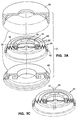
- Figure 3A is an exploded perspective view of an auxiliary gas-tight seal according to the invention showing its three main components.
- Figure 3B is an exploded cross-sectional view of auxiliary-gas-tight seal according to the invention:
- Figure 3C is a perspective view of the laterally-compliant seal of the auxiliary gas-tight seal according to the invention showing how laterally displacing an instrument inserted into the instrument port laterally displaces the instrument seal and the stabilizing ring.
- Figure 3D is a cross-sectional view of part of an alternative embodiment of the cap and the base of an auxiliary gas-tight seal according to the invention.
- Figure 4A is a cross-sectional view of the lower part of the base of the auxiliary gas-tight seal according to the invention and the rear housing of a trocar tube prior to engaging the lugs on the base with grooves in the rear housing.
- Figure 4B is a cross-sectional view of the lower part of the base of the auxiliary gas-tight seal according to the invention and the rear housing of a trocar tube prior to engaging the lugs on the base with grooves in the rear housing.
- Figure 4C is a cross-sectional view of the one of the lugs on the base of the auxiliary gas-tight seal according to the invention engaged with one of the grooves in the rear housing of the trocar tube.
- the drawing shows how the lug is tapered.
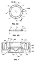
- Figure 5A is a cross-sectional view of the preferred embodiment of an auxiliary gas-tight seal with a conical instrument seal according to the invention.
- Figure 5B is an exploded cross-sectional view of the preferred embodiment of an auxiliary gas-tight seal with a conical instrument seal according to the invention.
- Figure 5C is a plan view of one of the stabilizing ring halves used in the preferred embodiment of an auxiliary gas-tight seal according to the invention.
- Figure 5D is a cross-sectional view of one of the stabilizing ring halves used in the preferred embodiment of an auxiliary gas-tight seal according to the invention.
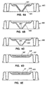
- Figure 6A is a cross-sectional view of the seal molding of an auxiliary gas-tight seal with a bimaterial conical instrument seal according to the invention.
- Figure 6B is a cross-sectional view of the seal molding of an auxiliary gas-tight seal with a first type of tapered conical instrument seal according to the invention.
- Figure 6C is a cross-sectional view of the seal molding of an auxiliary gas-tight seal with a second type of tapered conical instrument seal according to the invention.
- Figure 6D is a cross-sectional view of the seal molding of an auxiliary gas-tight seal with a tapered flat instrument seal according to the invention.
- Figure 6E is a cross-sectional view of the seal molding of an auxiliary gas-tight seal with a flat instrument seal with a recessed area around the instrument port according to the invention.
- Figure 7 is a cross-sectional view of an auxiliary gas-tight seal with a conical instrument seal and a proximally-extending compliant mounting according to the invention.
- Figure 8 is a cross-sectional view of a first alternative embodiment of an auxiliary gas-tight seal according to the invention.
- Figure 9 is a cross-sectional view of a second alternative embodiment of an auxiliary gas-tight seal according to the invention.
- Figure 10 is a cross-sectional view of a third alternative embodiment of an auxiliary gas-tight seal according to the invention.
- Figure 11A is a plan view of the stabilizing ring and instrument seal of an auxiliary gas-tight seal according to the invention including a first embodiment of a lateral force transmitting mechanism according to the invention.
- Figure 11B is a cross-sectional view of the stabilizing ring and instrument seal of the auxiliary gas-tight seal according to the invention including the first embodiment of the lateral force transmitting mechanism according to the invention.
- Figure 11C is a plan view of the stabilizing ring and instrument seal of the auxiliary gas-tight seal according to the invention including the first embodiment of the lateral force transmitting mechanism according to the invention with a larger-diameter instrument inserted.
- Figure 12A is a plan view of the stabilizing ring and instrument seal of an auxiliary gas-tight seal according to the invention including a second embodiment of the lateral force transmitting mechanism according to the invention.
- Figure 12B is a cross-sectional view of the stabilizing ring and instrument seal of the auxiliary gas-tight seal according to the invention including the second embodiment of the lateral force transmitting mechanism according to the invention.
- Figure 13 is a plan view of the stabilizing ring and instrument seal of an auxiliary gas-tight seal according to the invention including a third embodiment of the lateral force transmitting mechanism according to the invention.
- Figure 14A is a plan view of the stabilizing ring and instrument seal of an auxiliary gas-tight seal according to the invention including a fourth embodiment of the lateral force transmitting mechanism according to the invention.
- Figure 14B is a plan view of the stabilizing ring and instrument seal of the auxiliary gas-tight seal according to the invention including the fourth embodiment of the lateral force transmitting mechanism according to the invention with a larger-diameter instrument inserted into the instrument port.
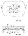
- Figure 15A is a plan view of an auxiliary gas-tight seal according to the invention including a fifth embodiment of a lateral force transmitting mechanism according to the invention.
- Figure 15B is a cross-sectional view of the auxiliary gas-tight seal according to the invention including the fifth embodiment of the lateral force transmitting mechanism according to the invention.
- the conventional gas-tight trocar tube seal uses the same piece of elastic material to form the gas-tight seal with the instrument, and to accommodate lateral displacement of the instrument.
- the need to accommodate lateral displacement of the instrument requires that, to prevent the seal from leaking, the radial force between the elastic material and the instrument be increased for an instrument at the minimum of the range of diameters. This reduces the maximum of the range of diameters above which there is excessive friction between the elastic material and the instrument.
- the gas-tight seal according to the invention uses different structures to provide the gas-tight seal with the instrument and to accommodate lateral displacement of the instrument. This enables the radial force between the gas-tight seal and the instrument to be reduced for an instrument at the minimum of the range of diameters. This, in turn, reduces friction between the seal and a larger-diameter instrument, and thus increases the maximum of the range of diameters.
- the gas-tight seal according to the invention presently provides a gas-tight seal with instruments having a greater than 3:1 range of diameters, and maintains the gas-tight seal when an instrument in the diameter range is laterally displaced.
- the present preferred embodiment provides a gas-tight seal with instruments ranging in diameter from 4 mm to 12 mm (0.16" to 0.48").
- the preferred embodiment of the gas-tight seal according to the invention will next be described.
- the preferred embodiment is an auxiliary gas-tight seal that is intended to be attached to the rear housing of a trocar tube after the trocar assembly has been used to puncture the body wall, and the trocar has been withdrawn from the trocar tube.
- the preferred embodiment is an auxiliary gas-tight seal because the self-shielding mechanism of the trocar of the trocar assembly sold by the patentee operates by snapping the trocar distally into the cannula after the trocar tip has penetrated the body wall.
- the trocar passes through a large-diameter, conventional gas-tight seal. If the gas-tight seal according to the invention were substituted for the conventional large-diameter gas-tight seal, friction between the gas-tight seal according to the invention and the trocar would be sufficiently high to impede the operation of the self-shielding mechanism.
- Friction in the gas-tight seal according to the invention is higher than in the large-diameter conventional gas-tight seal because the considerably smaller diameter instrument port in the gas-tight seal according to the invention. Nevertheless, friction in the gas-tight seal according to the invention is significantly reduced compared with a conventional gas-tight seal having the same diameter instrument port.
- the gas-tight seal according to the invention is not limited to use as an auxiliary gas-tight seal, however.
- a seal according to the invention could be built into, and form the main gas-tight seal in, a trocar tube for use in a trocar assembly in which the self-shielding mechanism does not move the trocar rapidly through the seal.
- a trocar is shown, for example, in United States Patent No. 4,601,710.
- FIG. 1 shows a perspective view of the auxiliary gas-tight seal 10 according to the invention aligned with the rear housing 12 of the trocar tube 14, just prior to attaching the auxiliary gas-tight seal to the rear housing.
- the rear face 16 of the rear housing 12 includes the main gas-tight seal 18 in its center.
- On opposite sides of rear face are the side walls 20 in which are formed the grooves 22.
- the rear housing includes the side walls 20 and the grooves 22 as part of the mounting for the two door-type auxiliary gas-tight seals (not shown) formerly fitted to the rear housing, as described above.
- the auxiliary gas-tight seal 10 includes lugs that engage in the grooves 22 to retain the auxiliary trocar seal in position on the rear face 16 of the rear housing 12. This way of attaching the auxiliary gas-tight seal 10 allows the auxiliary gas-tight seal 10 to replace the conventional door-type auxiliary gas-tight seals formerly fitted without the need to change the tooling used to mold the rear housing 12.
- FIG. 2 A cross section of the auxiliary gas-tight seal 10 attached to the rear housing 12 is shown in Figure 2.
- the auxiliary gas-tight seal 10 is shown in perspective and in cross section in Figures 3A and 3B, respectively.
- the auxiliary gas-tight seal 10 will now be described in detail with reference to these figures.
- the auxiliary gas-tight seal 10 includes three main components: the seal body 30 which attaches to the rear housing 12, the instrument seal 32, and the seal mounting 34 for the instrument seal 32.
- the instrument seal is a piece of a elastic material in which the instrument port 38 is formed, preferably in its center.
- the instrument seal 32 forms the gas-tight seal with an instrument passed through the instrument port 38.
- the instrument seal 32 is mounted in the seal mounting 34 to form the laterally-compliant seal 40.
- the seal mounting 34 is laterally compliant to allow the instrument seal 32 to move laterally in response to lateral movement of the instrument passed through the instrument port 38.
- the seal mounting 34 is preferably also axially stiff, to hold the instrument seal 32 in position axially when an instrument is inserted into or withdrawn from the instrument port.
- the seal mounting 34 includes the anchoring ring 42 and the stabilizing ring 44.
- the stabilizing ring includes the stabilizing ring halves 44A and 44B, and the locking pins 46.
- the preferred embodiment includes the seal molding 48, a part of which provides the instrument seal 32, and the rest of which provides part of the seal mounting 34.
- the seal molding 48 includes four distinct, radially separated zones, the instrument seal 32, the stabilizing ring anchor 50, the corrugated zone 52, and the anchoring ring 42.
- the seal molding 48 is made of an elastic material, preferably silicone rubber, but it can alternatively be molded from other suitable elastic materials, such as latex.
- the instrument seal 32 and the seal mounting 34 could alternatively be separate components joined at the stabilizing ring 44.
- This alternative construction is more complex, but enables different materials to be used for the instrument seal 32 and the seal mounting 34.
- the seal mounting 34 could be made from an inelastic material, such as MylarTM film.
- the part of the seal molding 48 providing the instrument seal 32 forms a gas-tight seal with an instrument (not shown) passed through the instrument port 38 in the center of the seal molding.
- the part forming the instrument seal 32 is relatively thick, about 1 mm (0.04") in the preferred embodiment. This enables this part of the seal molding to exert sufficient radial force against the instrument to form a gas-tight seal, even with an instrument at the minimum of the range of diameters.
- the part of the seal molding forming the instrument seal 32 is also relatively thick to prevent it from being torn when a hook-shaped instrument is withdrawn from the instrument port.
- the present embodiment accommodates instruments having a range of diameters, i.e., the instrument seal 32 forms a gas-tight seal with an instrument of a minimum diameter, and provides an acceptably low level of friction with an instrument as large as the maximum diameter.
- the minimum instrument diameter that can be accommodated depends on the diameter of the instrument port 38.
- the instrument port 38 is 3 mm (0.12") in diameter. With an instrument port of this diameter, the instrument seal 32 forms a gas-tight seal with an instrument as small as 4 mm (0.16”) in diameter.
- the preferred embodiment can be adapted to accommodate different ranges of instrument diameters by changing the diameter of the instrument port 38. For example, a 2.2 mm (0.09”) diameter instrument port will provide a gas-tight seal with a 3 mm (0.12") diameter instrument.
- the instrument When a larger-diameter instrument is inserted through the instrument port 38, the instrument stretches the elastomeric material of the seal molding 48 forming the instrument seal 32. This causes the part of the seal molding providing the instrument seal 32 to exert a radial force against the instrument, which results in friction between the instrument seal 32 and the instrument.
- the seal molding 48 is preferably coated with a dry lubricant. Reducing friction increases the maximum of the range of instrument diameters that the auxiliary gas-tight seal 10 can accommodate without excessive friction between the instrument and the instrument seal.
- the preferred dry lubricant is poly-p-xylxylene, a crystalline organic solid, a thin film of which is low vacuum deposited from the vapor phase onto the seal molding 48.
- Poly-p-xylxylene is sold under the brand name Parylene C by Union Carbide.
- An alternative dry lubricant is titanium, vapor deposited onto the surface of the seal molding 48.
- Other dry lubricants, sold by Spire Corporation, Bedford, MA, include: SPI-ARGENTTM and SPI-ARGENT II TM, which are ion beam deposited silver-based coatings; SPI-MetTM , and SPI-SiliconeTM .
- the seal mounting 34 for the instrument seal 32 comprises the stabilizing ring 44; and the stabilizing ring anchor 50, the corrugated zone 52, and the anchoring ring 42, all of which form part of the seal molding 48.
- the part of the seal molding 48 forming the anchoring ring 42 is considerably thicker than the part of the seal molding forming the instrument seal 32.
- the anchoring ring 42 is relatively rigid, and serves to locate the laterally-compliant seal 40 in the seal body 30.
- the anchoring ring is located in an annular groove formed by the inner annular step 58 in the base 60 and the annular step 64 in the cap 66.
- the face 54 and the face 56 of the anchoring ring contact the inner annular step 58 in the base 60, and the face 62 of the anchoring ring contacts the annular step 64 in the cap 66.
- the anchoring ring is slightly compressed between the annular step 64 and the inner annular step 58. This forms a gas-tight seal between the anchoring ring and the seal body.
- the part of the seal molding 48 forming the stabilizing ring anchor 50 is located between the instrument seal 32 and the corrugated zone 52.
- the stabilizing ring anchor 50 is an annular region in which the thickness of the seal molding 48 is increased on both sides.
- the stabilizing ring anchor serves to locate the seal molding 48 laterally with respect to the stabilizing ring 44.
- the corrugated zone 52 interconnects the stabilizing ring anchor 50 and the anchoring ring 42.
- the part of the seal molding 48 forming the corrugated zone 52 is between one tenth and one half of the thickness of the part of the seal molding forming the instrument seal 32.
- the part of the seal molding forming the corrugated zone is about 0.2 mm (0.008") thick, and is also corrugated, as shown.
- the thinness of the corrugated zone 52 and its corrugated structure provide lateral compliance between the inner periphery (i.e., the stabilizing ring 44) and the outer periphery (i.e., the anchoring ring 42) of the corrugated zone.
- the amount of radial force that must be applied to the stabilizing ring to displace laterally the stabilizing ring and the part of the corrugated zone to which it is attached is relatively small.
- the lateral force that an instrument passed through the instrument port 38 must apply to the instrument seal 32 to displace laterally the instrument seal 32, the stabilizing ring 44, and the part of the corrugated zone to which the stabilizing ring is attached is relatively small. Consequently, the additional radial force that the instrument seal 32 must apply to an instrument having a diameter at the minimum of the range of diameters to maintain the gas-tight seal with the instrument as the instrument is displaced laterally is also relatively small.
- Reducing the additional radial force reduces the radial force that the instrument seal 32 exerts when a larger-diameter instrument is inserted into the instrument port 38. This, in turn, reduces friction between the seal and the instrument and increases the range of instrument diameters that the seal can accommodate.
- the stabilizing ring 44 interconnects the instrument seal 32 and the corrugated zone 52, and transmits any radial force applied to the instrument seal 32 uniformly to the corrugated zone 52.
- the stabilizing ring 44 also preferably transmits axial forces resulting from inserting and withdrawing an instrument into and from the instrument port 38 directly to the seal body 30, i.e., to the base 60 when an instrument is inserted, and to the cap 66 when an instrument is withdrawn.
- the stabilizing ring by isolating axial forces from the corrugated zone 52, and by transmitting radial forces uniformly to the corrugated zone, enables the strength of the corrugated zone to be minimized, and the lateral compliance of the corrugated zone to be maximized.
- the stabilizing ring 44 comprises the stabilizing ring halves 44A and 44B, and the pins 46.
- the stabilizing ring halves are annulus-shaped moldings of a suitable low-friction plastic, such as ABS, polycarbonate, or PTFE.
- Each stabilizing ring half includes in one face the annular groove 68 that mates with the stabilizing ring anchor 50 in the seal molding 48.
- the stabilizing ring halves 44A and 44B are held in place on opposite sides of the seal molding 48 by the plural pins 46 inserted through one of the stabilizing ring halves (e.g., the stabilizing ring half 44A), the stabilizing ring anchor 50, and the other of the stabilizing ring halves (e.g., the stabilizing ring half 44B).
- the pins 46 pass through the stabilizing ring anchor 50, where the material of the seal molding 48 is thicker, and forms a gas-tight seal with each pin 30. This prevents the pins 46 from providing a gas leakage path.
- the elastic material surrounding the instrument port is rigidly mounted at its periphery.
- the elastic material surrounding the instrument port stretches to accommodate lateral displacement of the instrument. Sufficient excess radial force must be provided between the elastic material and the instrument to keep the elastic material remote from the direction of the lateral displacement in contact with the instrument and therefore preserve the gas-tight seal.
- the elastic material surrounding the instrument port 38 is also rigidly mounted at its periphery, but the rigidly-mounted elastic material is, in turn, compliantly mounted.
- the seal mounting 34 allows the whole of the instrument seal 32 to move laterally. This is illustrated in Figure 3C, in which the center line 41 of the instrument (not shown) is displaced laterally to the point indicated by the line 43.
- the lateral movement of the instrument seal is accommodated by the corrugated zone 52, the thin, corrugated material of which makes it laterally compliant.
- the laterally-compliant seal 40 requires that considerably less excess radial force be provided between the instrument seal and the instrument to maintain contact with instrument when the instrument is laterally displaced. This, in turn, reduces the amount of friction between the instrument seal and the instrument when a larger-diameter instrument is inserted into the instrument port, and allows the seal to accommodate a larger range of instrument diameters.
- the seal body 30 includes the base 60 and the cap 66, as shown in Figure 3A.
- the base 60 is a molding of a suitable plastic, such as ABS, or polycarbonate.
- the base includes the internal face 70 over which the stabilizing ring 44 of the seal mounting 34 can slide laterally.
- the base also includes the inner annular step 58 and the outer annular step 80.
- the inner annular step 58 together with the annular step 64 in the cap, locates the anchoring ring 42 of the seal molding 48, as described above.
- the outer annular step 80 abuts the edge 81 of the cap 60, which defines the axial location of the cap 66 relative to the base 60.
- This defines the amount of compression applied to the anchoring ring 42 when the cap and the base are mated to form the seal body 30. This also defines the clearance between the internal face 70 of the base 60 and the internal face 78 of the cap 66, and hence the clearance between the stabilizing ring 44 and the internal faces 70 and 78.
- the base also includes the bore 72, which has a diameter of slightly greater than the diameter as the largest-diameter instrument that can be accommodated by the main gas-tight seal in the trocar tube, plus twice the thickness of the instrument seal 32.
- Surrounding the bore 72 are the lugs 74 and the plane sealing surface 76 with which the auxiliary gas-tight seal 10 is attached to the rear face 16 of the rear housing 12 ( Figure 1).
- the lugs 74 are preferably tapered.
- the lugs 74 and the plane sealing surface 76 are specific to the preferred way of attaching the auxiliary gas-tight seal 10 to the rear housing of the trocar tube sold by the patentee.
- the auxiliary gas-tight seal 10 could be attached to the rear housing of the trocar tube made by the patentee in other ways, which would require a different arrangement of the base 60 and/or the cap 66.
- the auxiliary gas-tight seal 10 could be adapted for attaching to the rear housings of trocar tubes made by others, which might also require a different arrangement of the base 60 and/or the cap 66.
- a gas-tight seal similar to the auxiliary gas-tight seal 10 can be built into the rear housing of a trocar tube, in which case, the base 60 would be formed as part of the rear housing molding.
- the cap 66 is also a molding of a suitable plastic such as ABS or polycarbonate.
- the cap fits over the base 60, and includes the internal face 78, with respect to which the stabilizing ring 44 of the seal mounting 34 can slide laterally.
- the cap 66 also includes the inner annular step 64 and the edge 81.
- the annular step 64 clamps the anchoring ring 42 of the seal molding 48 into the annular step 58 in the base 60, as described above.
- the edge 81 defines the relative axial location of the base and the cap, as described above.
- the cap 66 also includes the central bore 82, which also has a diameter of slightly greater than the diameter as the largest-diameter instrument that can be accommodated by the main gas-tight seal in the trocar tube, plus twice the thickness of the instrument seal 32.
- the cap 66 is attached to the base 60 by a suitable snap arrangement, a suitable adhesive, by ultrasonic welding, or by some other suitable method.
- the cap may be adapted for attaching the auxiliary gas-tight seal 10 to the rear housing of the trocar tube in addition to, or as an alternative to, the attachment arrangements on the base 60 already described.
- the cap 66A may be formed with two annular steps, and the base 60A may be formed with a single annular step, as shown in Figure 3D.
- the cap 66A is formed with an inner annular step 64A and an outer annular step 80A, and the base is formed with the wide annular step 58A.
- the annular groove formed between the inner annular step 64A in the cap 66A and the inner part of the wide annular step 58A in the base locates and seals with the anchoring ring 42.
- the outer part of the wide annular step 58A in the base 60A abutting the outer annular step 80A in the cap 66A defines the relative axial location of the base and the cap.
- Figure 2 shows a cross sectional view of the auxiliary gas-tight seal 10 in place on the rear face 16 of the housing 12 of the trocar tube 14.
- the main gas-tight seal 18 is an elastomeric molding that engages with the rear face 16 as shown.
- the main gas-tight seal includes the main sealing lip 84, which seals with the trocar (not shown) or other instrument passed through the main gas-tight seal.
- the main gas-tight seal also includes the annular inner sealing lip 86, which forms a gas-tight seal with the spring-loaded door 88.
- the spring-loaded door 88 swings in the direction indicated by the arrow 90 to form a seal with the inner sealing lip 86 when no instrument is inserted into the main gas-tight seal 18.
- the main gas-tight seal 18 also includes the annular outer sealing lip 92, which is provided to form a gas-tight seal with the door-type auxiliary gas-tight seal formerly included in the rear housing, as described above.
- the outer sealing lip 92 forms a gas-tight seal with the plane sealing surface 76 of the base 60 of the auxiliary gas-tight seal 10, as shown.
- the plane sealing surface 76 is kept in contact with the outer sealing lip 92 by the lugs 74 engaging in the grooves 22 in the rear housing 12.
- FIGs 4A and 4B show a cross section of the rear housing 12 and part of the base adjacent to the lugs 74 before and after engaging the lugs in the grooves 22.
- Each lug includes a cut-away part 94, which enables the lugs to fit between the walls 20.
- the surgeon grasps the rear housing in one hand, holds the auxiliary gas-tight seal in the other, and presents the auxiliary gas-tight seal to the rear housing such that the cut-away part 94 of each lug is inserted between the walls 20, as shown in Figure 4A. The surgeon then rotates the auxiliary gas-tight seal in a clockwise direction, looking from the top, to engage the lugs 74 into the grooves 22.
- the lugs 74 are tapered, as shown in Figure 4C, such that, as the auxiliary gas-tight seal is rotated, the tapered lugs engaging with the grooves 22 moves the plane sealing face 76 into engagement with the outer sealing lip 92 (see Figure 2).
- the surgeon stops rotating the auxiliary gas-tight seal when the stop 96 on each lug is fully engaged with the corresponding stop 98 in the grooves 22.
- Juxtaposing the stop 96 with the stop 98 and the lugs 74 with the grooves 22 positively locates the auxiliary gas-tight seal 10 in all three dimensions relative to the rear housing 12.
- the surgeon can then insert an instrument having any diameter in the specified range of diameters accommodated by the gas-tight seal into the bore 82, and then through the instrument port 38.
- the surgeon can move a smaller-diameter instrument laterally to the extent defined by the bore 82, if desired.
- auxiliary gas-tight seal 10 can remove the auxiliary gas-tight seal 10 at any time simply by removing the instrument from the auxiliary gas-tight seal, rotating the auxiliary gas-tight seal 10 counter-clockwise until the lugs 74 disengage from the grooves 22, and withdrawing the auxiliary gas-tight seal from the rear housing 12.
- auxiliary gas-tight seal 10 The shape of the auxiliary gas-tight seal 10 and the simple attachment mechanism makes it easy to attach the auxiliary gas-tight seal to, and to remove the auxiliary gas-tight seal from, the rear housing 12 of the trocar tube 14, even with gloved hands.
- the preferred embodiment of the auxiliary gas-tight seal can accommodate instruments having a 3:1 range of diameters, for example, from 4 mm to 12 mm, the auxiliary gas-tight seal will be fitted to the trocar tube immediately after the trocar has been removed from the trocar tube, and will remain attached to the trocar tube throughout the rest of the procedure.
- auxiliary gas-tight seal according to the invention will next be described, together with some variations on the preferred embodiment.
- Testing of the auxiliary gas-tight seal shown in Figures 1 through 4C showed good results with most types of instruments having a wide range of diameters. Testing showed, however, that a large-diameter instrument with a pronged distal end, such as certain types of clip applier, would penetrate the flat instrument seal 32 at points remote from the instrument port 38 instead of entering the instrument port and stretching the material of the instrument seal surrounding the instrument port. Penetration of the instrument seal reduces the effectiveness of the seal. Testing also showed that a further increase in lateral compliance was desirable. Finally, production considerations made it desirable to find a better way of attaching the stabilizing ring halves 44A and 44B to one another than by the pins 46.
- FIG. 5A A cross sectional view of the preferred embodiment of the auxiliary gas-tight seal 10B according to the invention is shown in Figure 5A. Components that correspond to components shown in Figures 1 through 4C use the same reference number with the letter "B" added.
- a cross-sectional exploded view of the seal molding 48B, the base 60B, the cap 66B and the stabilizing ring halves 44AB and 44BB are shown in Figure 5B.
- a plan and cross sectional view of a stabilizing ring half are shown in Figures 5C and 5D, respectively.
- the seal molding 48B retains the four zones, namely, the instrument seal 32B, the stabilizing ring anchor 50B, the corrugated zone 52B, and the anchoring ring 42B, described above. Of these, the stabilizing ring anchor and the anchoring ring are unchanged, and so will not be further described.
- the instrument seal 32B has a distally-extending conical shape centered on the instrument port 38B.
- the revised shape of the instrument seal 32B reduces the ability of an instrument with a pronged distal end to penetrate the instrument seal by generating a lateral component from the force between the instrument and the instrument seal.
- the lateral component laterally displaces the material surrounding the instrument port and enables the pronged end of the instrument to enter the instrument port. In other words, the pronged end of the instrument is guided up the conical sides of the instrument seal and enters the instrument port.
- the included angle of the conical instrument seal 32B is in the range of 60 to 120 degrees. Reducing the angle increases the ability of the instrument seal to resist penetration, but increases friction between the instrument and the seal.
- the current preferred angle is 75 degrees.
- the thickness of the conical instrument seal 32B is in the range of 0.02" to 0.06" (0.51 - 1.52 mm), with a preferred thickness of 0.03" (0.76 mm).
- the preferred material of the seal molding 48B is silicone rubber. Silicone rubber has excellent rebound, i.e., ability to recover after deformation, but a less good ability to resist penetration. Polyurethane is an alternative material for the seal molding: the penetration resistance of polyurethane is superior to that of silicone rubber, but its rebound is inferior.
- the seal molding 48 B would be of silicone rubber with the conical instrument seal part 32X of the molding about 0.02" (0.5 mm) thick.
- the internal (instrument contacting) part 32Y of the instrument seal 32C would be formed of polyurethane about 0.005" (0.12 mm) thick, attached to the instrument seal part of the seal molding.
- At least the instrument seal 32B of the seal molding 48B is coated with an anti-friction coating, as described above.
- the corrugated zone 52 shown in Figures 1 through 4C uses a folded arrangement accommodated within the overall height of the stabilizing ring 44.
- the lateral compliance of the corrugated zone 52B has been increased by forming the corrugated zone from a series of substantially vertical elements 51, 53, 55, interconnected by substantially semicircular sections 57, 59, 61. Compliance is further increased by making the vertical elements 51, 53, 55 substantially longer than the sloped elements of the corrugated zone 52 shown in Figure 3A. This results in the auxiliary gas-tight seal 10B being considerably taller than the seal auxiliary gas-tight seal 10 shown in Figures 1 through 4C.
- the material of the corrugated zone 52B bends and/or buckles to accommodate the lateral movement of the instrument seal 32B and stabilizing ring 44B. This requires considerably less force than stretching the material of the corrugated zone.
- the preferred thickness of the corrugated zone 52B is little changed from that of the corrugated zone 52 shown in Figure 3A.
- the base 60B is changed to accommodate the greater height of the corrugated zone 52B and to allow the conical instrument seal 32B to move laterally.
- the thickness of the base is increased.
- the face 70B occupies a relatively small fraction of the area of the base, and is surrounded by the annular pocket 63 that accommodates the corrugated zone 52B.
- the diameter of the bore 72B shown in Figures 5A and 5B is increased. This is necessary because the bore must accommodate not only the instrument, it must also accommodate the instrument seal 32B, and the maximum lateral excursion of the instrument seal. To provide the necessary diameter of the bore, and to provide an adequate area on the plane sealing face 76B, the bore is tapered towards the plane sealing face 76B as shown.
- the cap 66B is similar to the cap 60 shown in Figure 3A, except that its height is increased to accommodate the increased height of the corrugated zone 58B and the cap 60B.
- the cap is formed with two internal circumferential steps 64B and 80B.
- the anchoring ring is located in the annular groove formed between the outer face 58B of the outer wall 65 of the annular pocket 63, the annular part 67 of the base 60B outside the wall 65, and the circumferential step 64B in the cap.
- the annular groove locates and forms a gas-tight seal with the anchoring ring 42B.
- the part 67 of the base fits into the circumferential step 80B and defines the relative axial location of the base and the cap. This, in turn, defines the compression of the anchoring ring 42B, and the distance between the faces 70B and 78B.
- the stabilizing ring 44B is formed of two identical stabilizing ring halves 44AB and 44BB, as shown in Figures 5A and 5B.
- One of the stabilizing ring halves 44AB is shown in plan and in cross section in Figures 5C and 5D, respectively.
- Each stabilizing ring half is an annular plastic ring half molding 71.
- Formed in one plane face of the molding is the annular groove 73 that accommodates the stabilizing ring anchor 50B of the seal molding 48B.
- the pins 75 In four equally-spaced locations in the annular groove are formed the pins 75, and in four equally-spaced locations, spaced equally between the pins 75, are formed the pin holes 77.
- Eight equally-spaced pin holes 79 are also formed in the stabilizing ring anchor in the seal molding 48B.
- the two stabilizing ring halves 44AB and 44BB are attached to the seal molding 48B simply by inverting, and rotating through 45 degrees, one ring half molding 71 relative to the other.
- the ring half pins 75 are then inserted through the pin holes 79 in the seal molding, and are pressed into the pin holes 77 in the other ring half, where they are retained by friction.
- the thickness of instrument seal 32D and 32E may be radially varied to provide a better relationship between penetration resistance and friction between the instrument seal and the instrument.
- Figure 6B shows the thickness of the instrument seal 32D decreasing with distance from the center of the instrument port 38D.
- Figure 6C shows the thickness of the instrument seal 32E increasing with distance from the center of the instrument port 38E.
- the thickness of the instrument seal may be radially varied in steps to facilitate stretching of the instrument seal and to reduce friction between the instrument seal and the instrument.
- the instrument-contacting surface of the instrument may be formed with flutes extending from the instrument port to the stabilizing ring anchor, or with a textured, marbled, or matt finish.
- scales, or cut-resistant elements such as overlapping polyurethane scales, may be mechanically attached to, bonded to, or formed in the instrument-contacting surface of the instrument seal to increase the penetration resistance of the surface and to reduce friction between the instrument seal and the instrument.
- the basic conical shape of the instrument seal 32B and its thickness could be varied to provide an optimum relationship between penetration resistance and friction between the instrument seal and the instrument.
- the shape of the instrument seal would be more complex than the simple conical shape shown, for example, in Figures 5A and 5B.
- the radial variation of thickness would be more complex than the simple linear taper shown in Figures 6B and 6C.
- Thickness tapering may also be applied to the flat instrument seal, as shown in Figure 6D.
- the flat instrument seal 32F has a thickness of about 0.06" (1.5 mm) at its outer periphery, adjacent to the stabilizing ring anchor 50F. The thickness gradually tapers to about 0.035" (0.9 mm) at the periphery of the instrument port 38F.
- the thickness of the instrument seal may also be selectively reduced adjacent to the instrument port, as shown in Figure 6E.
- the instrument seal 32G has a thickness of about 0.06" (1.5 mm) at its outer periphery, adjacent to the stabilizing ring anchor 50G.
- the thickness is reduced to about 0.04" (1 mm) in an annular area 81 surrounding the instrument port 38.
- the annular area has an outside diameter of about 0.12" (3 mm).
- FIG 7 shows an alternative embodiment in which the corrugated section 52C of the seal molding 48C extends proximally instead of distally.
- the seal molding also includes the conical instrument seal 32C.
- the base 60C and the cap 66C are changed.
- the base 60C retains the large internal face 70C of the arrangement shown in Figure 3A.
- the plane face 70C terminates in the peripheral wall 65C.
- the bore 72C has a large diameter to accommodate the instrument, the conical instrument seal, and the lateral movement of the instrument seal.
- the cap 66C has the internal face 78C that occupies a small part of the area of the cap, and is surrounded by the annular pocket 83 that accommodates the corrugated zone 52C.
- the bore 82C is flared towards the plane face 78C.
- the tunnel between the proximal face 85 of the cap and the instrument port 38C at the distal end of the instrument seal guide the instrument towards the center of the instrument port and facilitate passage of the instrument through the instrument port.
- FIG 8. An alternative embodiment of the auxiliary gas-tight seal according to the invention is shown in Figure 8.
- this embodiment which is based on the embodiment shown in Figures 1 through 4C, parts that are similar to those in the preferred embodiment shown in Figures 3A and 3B are numbered with the same reference numbers with 100 added.
- a different configuration of the seal mounting is used; the instrument seal 132 and the seal mounting 134 are provided using separate components; and the shapes of the cap 166 and the base 160 constituting the seal body 130 are changed.
- the instrument seal 132 is similar to the instrument seal 32 shown in Figures 3A and 3B, and is molded of an elastic material, such as silicone rubber, with the stabilizing ring anchor 150 as its outer periphery.
- the instrument seal includes the instrument port 138.
- the seal mounting 134 includes the stabilizing ring 144, the stabilizing ring anchor 150, and the corrugated seal 121.
- the stabilizing ring 144 includes the stabilizing ring halves 123 and 125, which mate with the stabilizing ring anchor 150.
- the stabilizing ring half 123 is similar to the stabilizing ring halves 44A and 44B shown in Figures 3A and 3B, but its outer curved face 127 is changed because there is no seal molding to pass through it.
- the stabilizing ring half 125 is substantially changed relative to the stabilizing ring half 44B.
- the plane face 129 of the stabilizing ring half 125 is extended radially inwards toward the instrument port 138, and then is extended axially away from the instrument seal 132 to form the lip 131.
- the lip 131 defines the periphery of a bore 133 which has a diameter about 50% greater than the diameter of the bore 164 in the cap 166.
- the corrugated seal 121 is a molding of an elastic material, for example, silicone rubber.
- the corrugated seal includes an inner anchoring ring 137 and an outer anchoring ring 139 interconnected by a corrugated section 141.
- the anchoring rings are preferably thicker than the corrugated section.
- the inner anchoring ring 137 is adapted for attaching to the lip 133 by means of a suitable adhesive, a metal or plastic clamp (not shown), or some other suitable means.
- the outer anchoring ring 139 is adapted for attaching to the base 160 by means of a suitable adhesive, a metal or plastic clamp (not shown), or some other suitable means.
- the outer anchoring ring can be compressed in an annular groove (not shown) formed between a step on the base 160 and a corresponding step on a suitable annular sleeve (not shown) fitting inside the base similar to the way in which the base fits inside the cap in Figures 3A and 3B.
- the alternative embodiment shown in Figure 8 operates similarly to the preferred embodiment described with reference to Figures 3A and 3B.
- the instrument seal 132 is free to move laterally between the cap 166 and the base 160. This allows the excess radial force between the instrument seal 132 and the instrument to be reduced, which, in turn, reduces friction between the instrument seal 132 and an instrument having a diameter at the maximum of the range of diameters.
- the seal can accommodate a greater range of instrument diameters without leaking and without excessive friction.
- the stabilizing ring 144 isolates the instrument seal 132 from the seal mounting 134, as before, and also transfers axial forces directly from the instrument seal 132 to the seal body 130, comprising the cap 166 and the base 160.
- the seal mounting 134 is laterally compliant while providing a gas-tight seal between the seal body 130 and the instrument seal 132. To move the instrument seal 132 laterally requires that the instrument exert relatively little radial force on the instrument port 138.
- a conical instrument seal similar to that shown in Figure 5A, may be substituted for the flat instrument seal 132.
- FIG 9 parts that are similar to the embodiments shown in Figures 3A and 3B, and Figure 8 are numbered with the same reference numbers with 100 or 200, respectively, added.
- the base 260 and the cap 266 are similar to the base 60 and the cap 66 shown in Figures 3A and 3B, except that no provision is made for mounting the anchoring ring 42 ( Figures 3A and 3B).
- the instrument seal 232 is similar to the instrument seal 132 shown in Figure 8. As in Figure 8, the instrument seal 232 is molded with the stabilizing ring anchor 250 at its periphery.
- the stabilizing ring anchor 250 mates with the stabilizing ring halves 251 and 253, respectively.
- Both stabilizing ring halves 251 and 253 are similar to the stabilizing ring half 123 shown in Figure 8, but the plane face of each stabilizing ring half is modified to include the projecting annular wiper 255 and 257, respectively.
- a groove can be formed in the flat surface of each stabilizing ring half, and an annular wiper of a different material can be affixed into the groove.
- the wiper 255 contacts internal face 278 of the cap 266.
- the wiper 257 contacts the internal face 270 of the base 260.
- Contact between the wiper 257 and the internal face 270 forms a primary sliding gas-tight seal.
- Contact between the upper wiper 255 and the internal face 278 forms a secondary gas-tight seal that seals any gas that escapes past the primary sliding gas-tight seal.
- the axially-opposed primary and secondary gas-tight seals require a relatively small axial force between the wipers and their respective internal faces to provide an effective gas-tight seal.
- This seal remains gas-tight when an axial load is imposed on the seal, such as that imposed when an instrument is inserted or withdrawn, despite the small force between the wipers and their respective sealing faces. It is desirable to have a relatively small force between the wipers and their respective sealing surfaces to minimize friction, and thus maximize the lateral compliance of the instrument seal 232. Friction can be further reduced by coating the wipers 255 and 257 and the internal faces 270 and 278 with a suitable anti-friction layer.
- a conical instrument seal similar to that shown in Figure 5A, may be substituted for the flat instrument seal 232.
- Figure 10 shows a simplified version of the arrangement shown in Figure 9 in which the wipers are omitted from the stabilizing ring 344. Parts similar to parts shown in Figure 9 are numbered with the same reference numbers with 100 added.
- the internal faces 370 and 378, the mating surfaces of the cap 366 and the base 360, and the plane surfaces of the stabilizing ring 344 are formed with sufficient precision that the gap between the plane faces of the stabilizing ring and the respective internal faces of the cap and the base is of the order of 25 ⁇ m (0.001"). This dimension is large enough to allow the stabilizing ring to slide freely between the cap and the base. Gas pressure acting on the instrument seal 332 moves the plane surface 365 of the stabilizing ring half 323 into contact with the internal face 378.
- a conical instrument seal similar to that shown in Figure 5A, may be substituted for the flat instrument seal 332.
- the radial force between the instrument seal 32 ( Figure 3A) and the instrument can be further reduced by transmitting directly from the instrument to the stabilizing ring the lateral force required to move the seal mounting 34 laterally. This relieves the instrument seal of the task of transmitting this lateral force, which enables the radial force between the instrument seal and a minimum-diameter instrument to be further reduced. Reducing the radial force between the instrument seal and a minimum-diameter instrument increases the range of instrument diameters that the seal can accommodate.
- FIGS 11A-11C, 12A, 12B, 13, 14A and 14B only show the stabilizing ring 444 and the instrument seal 432.
- the lateral force transmitting mechanism embodiments shown in these Figures and in Figures 15A and 15B may be applied to any of the embodiments and variations shown in Figures 3A and 3B, 5A, 5B, 6A through 6E, 7, 8, 9, and 10, all of which include a stabilizing ring and an instrument seal.
- the thickness of one of the stabilizing ring halves comprising the stabilizing ring 444 is increased to accommodate the lateral force transmitting mechanism.
- the increase in the thickness of the stabilizing ring half 423 is relatively small because the simple lateral force transmitting mechanism has a relatively low profile.
- the more complex lateral force transmitting mechanisms shown in Figures 12A and 12B, 13, and 14A and 14B require a greater increase in the thickness of the stabilizing ring half 423.
- wire springs 469, 471, and 473 are attached in a radially-symmetrical arrangement to the stabilizing ring half 423.
- the wire springs are radially offset so that they are substantially tangential to the instrument port 438.
- the parts of the wire springs adjacent to the instrument port 438 may overlap one another as shown. This may be achieved by appropriately bending each wire spring, or by mounting each wire spring at a different point in the thickness of the stabilizing ring, as shown in Figure 11B.
- the wire springs 469, 471, and 473 are biased into contact the instrument, such as the instrument I, inserted into the instrument port 438.
- the wire springs exert a radial compressive force against the instrument.
- the compressive force is as radially symmetrical as is possible with a radial force applied by three discrete elements.
- the compressive force can be made more symmetrical at the expense of greater complexity by increasing the number of wire springs.
- the instrument When the instrument I is moved laterally, the instrument applies a lateral force to one or more of the wire springs 469, 471, and 473. Each wire spring to which the lateral force is applied transmits the lateral force directly to the stabilizing ring 444. The lateral force thus applied directly to the stabilizing ring moves the stabilizing ring and the instrument seal 432 laterally with the lateral movement of the instrument. In this way, the lateral force transmitting mechanism moves the instrument seal laterally and considerably reduces the force between the instrument seal and the instrument required to move the instrument seal laterally.
- the elasticity of the wire springs 469, 471, and 473 enables the wire springs to move radially when a larger-diameter instrument, such as the instrument I' shown in Figure 11C, is inserted into the instrument port.
- the wire springs 469, 471, and 473 exert a radial force against the instrument. This radial force increases with increasing diameter of the instrument. However, friction on the instrument resulting from the radial force exerted by the wire springs is less than that resulting from the radial force exerted by the instrument seal because the coefficient of friction between the wire springs and the instrument is less than that between the instrument seal and the instrument.
- the parts of the wire springs 469, 471, and 473 remote from the stabilizing ring 444 may be fitted with suitably-shaped paddles to make inserting the instrument easier. Inserting the instrument may be made even easier by fitting each wire spring with a roller, as shown in Figures 12A and 12B.
- Each of the wire springs 469, 471, and 473 is fitted with a roller 475, 477, and 479, respectively.
- Each roller is free to rotate on its respective wire spring, and is axially located on the wire spring by bushes, or some other suitable device.
- the bushes 481 and 483 are shown retaining the roller 477 on the wire spring 471, for example.
- the radial force applied to the instrument by the lateral force transmitting mechanism can be made less dependent on the instrument diameter increases by making the wire springs longer, as shown in Figure 13.
- the wire springs 469A, 471A, and 473A are curved, which enables their length to be increased within the confines of the stabilizing ring 444.
- the rollers 475, 477, and 479 can be omitted, or can be replaced by paddles, if desired.
- rollers 475, 477, and 479 are mounted on the axles 485, 487, and 490, respectively.
- the axles 485, 487, and 489 swivel on the pins 491, 493, and 495 mounted on the stabilizing ring 444.
- a hairspring arrangement 495 biases each pivoted axle towards the instrument port 438. Such an arrangement makes the radial force applied to the instrument by the lateral force transmitting mechanism less dependent on the instrument diameter.
- a conical instrument seal similar to that shown in Figure 5A, may be substituted for the flat instrument seal 432.
- FIGS 15A and 15B show an arrangement of spring-loaded bumpers.
- Each of the four bumpers 511, 513, 515, and 517 is mounted on a compression spring 519, 521, 523, and 525 inside the stabilizing ring 544.
- This arrangement exerts a radial compressive force against an instrument inserted into the instrument port 538.
- the bumpers and springs transmit a lateral force directly to the stabilizing ring 544. This moves the instrument seal 532 laterally, and considerably reduces the force between the instrument seal and the instrument required to move the instrument seal laterally.
- a conical instrument seal and a corrugated section may be substituted for the flat instrument seal 532, and the corrugated section 552.
Landscapes
- Health & Medical Sciences (AREA)
- Heart & Thoracic Surgery (AREA)
- Life Sciences & Earth Sciences (AREA)
- Public Health (AREA)
- Biomedical Technology (AREA)
- Engineering & Computer Science (AREA)
- Animal Behavior & Ethology (AREA)
- General Health & Medical Sciences (AREA)
- Veterinary Medicine (AREA)
- Surgery (AREA)
- Hematology (AREA)
- Pulmonology (AREA)
- Anesthesiology (AREA)
- Pathology (AREA)
- Nuclear Medicine, Radiotherapy & Molecular Imaging (AREA)
- Medical Informatics (AREA)
- Molecular Biology (AREA)
- Surgical Instruments (AREA)
- Materials For Medical Uses (AREA)
- Sealing Material Composition (AREA)
- Dental Tools And Instruments Or Auxiliary Dental Instruments (AREA)
Claims (47)
- Dichtungseinrichtung zur Verwendung in einem chirurgischen Instrument, um eine gasdichte Abdichtung mit einem Gerät (I) zu bilden, das durch die Dichtung hindurchgeführt wird, wobei das Gerät (I) einen Durchmesser in einem breiten Durchmesserbereich aufweist, und die Dichtungseinrichtung (10; 10B) versehen ist mit:einem Dichtungskörper (30), der eine Bohrung aufweist, durch die das Gerät hindurchgeführt wird, wobei die Bohrung eine Achse aufweist; und einer Gerätdichtung (32; 32B; 32C; 32D; 32E; 32F; 32G; 132; 232; 332; 432; 532) aus elastischem Werkstoff, wobei die Gerätdichtung eine Gerätöffnung (38; 38B; 38C; 38D; 38E; 138; 238; 338; 438; 538) aufweist, durch welche das Gerät (I) in einer Einführrichtung hindurchgeführt wird, wobei die Gerätöffnung im Wesentlichen senkrecht zur Bohrungsachse ist; und die Gerätdichtung sich von der Gerätoffnung radial nach aussen und axial in der Richtung der Bohrungsachse erstreckt;gekennzeichnet durch eine seitlich nachgiebige Dichtungshalteeinrichtung (34; 134) zum:Haltern der Gerätdichtung (32; 32B; 32C; 32D; 32E; 32F; 32G; 132; 232; 332; 432; 532) am Dichtungskörper (30),Formen einer gasdichten Abdichtung zwischen der Gerätdichtung und dem Dichtungskörper (30), undZulassen einer freien seitlichen Bewegung der Gerätdichtung ansprechend auf eine seitliche Bewegung des Gerätes (I).
- Dichtungseinrichtung nach Anspruch 1, wobei
der Dichtungskörper eine erste, innere Fläche (270; 370) gegenüberliegend einer zweiten, inneren Fläche (278; 378) aufweist, und die inneren Flächen um die Bohrung angeordnet sind;
die seitlich nachgiebige Dichtungshalteeinrichtung einen starren Ringkörper (244; 344) aufweist, der verschiebbar gehalten ist zwischen der ersten, inneren Fläche und der zweiten, inneren Fläche, und
die Gerätdichtung (232; 332) an dem starren Ring (244; 344) befestigt ist wobei die Gerätöffnung (238; 338) innerhalb des Ringkörpers (244; 344) liegt. - Dichtungseinrichtung nach Anspruch 2, wobei die Gerätdichtung (232; 332) mit einer Beschichtung mit geringen Reibungswiderstand überzogen ist.
- Dichtungseinrichtung nach Anspruch 2, wobei der starre Ringkörper (244) eine erste, ebene Fläche (367) gegenüberliegend einer zweiten, ebenen Fläche (365) aufweist, und in dem Dichtungskörper gehalten ist mit der ersten, ebenen Fläche (367) gegenüberliegend der ersten, inneren Fläche (370) des Dichtungskörpers zur Anlage an der ersten, inneren Fläche (370), und der zweiten, ebenen Fläche (365) gegenüberliegend der zweiten, inneren Fläche (378) des Dichtungskörpers zur Anlage an der zweiten, inneren Fläche (378).
- Dichtungseinrichtung nach Anspruch 2, wobei die seitlich nachgiebige Dichtungshalteeinrichtung des Weiteren aufweist:einen ersten, ringförmigen Schleiferansatz (257), der an einer ersten, ebenen Fläche des starren Ringkörpers (244) befestigt ist und mit der ersten, inneren Fläche (270) des Dichtungskörpers in Berührung ist; undeinen zweiten, ringförmigen Schleiferansatz (255), der an einer zweiten, ebenen Fläche des starren Ringkörpers (244) befestigt ist und mit der zweiten, inneren Fläche (278) des Dichtungskörpers in Berührung ist.
- Dichtungseinrichtung nach Anspruch 5, wobei die Gerätdichtung (232) mit einer Beschichtung mit geringem Reibungswiderstand überzogen ist.
- Dichtungseinrichtung nach Anspruch 1, wobei die seitlich nachgiebige Dichtungshalteeinrichtung (134) versehen ist mit:einem starren Ringkörper (144), undeinem seitlich nachgiebigen Ringkörper (121), der zwischen dem starren Ringkörper (144) und dem Dichtungskörper angeordnet ist, und die Gerätdichtung (132) am starren Ringkörper (144) befestigt ist, wobei die Gerätöffnung (138) sich innerhalb des Ringes (144) befindet.
- Dichtungseinrichtung nach Anspruch 7, wobei:der Dichtungskörper eine erste, innere Fläche gegenüberliegend einer zweiten, inneren Fläche aufweist, und die inneren Flächen um die Bohrung angeordnet sind; undder starre Ringkörper (144) verschiebbar gehalten ist zwischen der ersten, inneren Fläche und der zweiten, inneren Fläche.
- Dichtungseinrichtung nach Anspruch 7, wobei die Gerätdichtung (132) mit einer Beschichtung mit geringem Reibungswiderstand überzogen ist.
- Dichtungseinrichtung nach Anspruch 7, wobei der seitlich nachgiebige Ringkörper (121) gewellt ist und sich zwischen dem starren Ringkörper (144) und einem Teil des Dichtungskörpers befindet, der axial von dem starren Ringkörper (144) und der Gerätdichtung (132) versetzt ist.
- Dichtungseinrichtung nach Anspruch 10, wobei:der Dichtungskörper eine erste, innere Fläche gegenüberliegend einer zweiten, inneren Fläche aufweist, und die inneren Flächen um die Bohrung angeordnet sind; undder starre Ringkörper (144) verschiebbar gehalten ist zwischen der ersten inneren Fläche und der zweiten, inneren Fläche.
- Dichtungseinrichtung nach Anspruch 11, wobei:der Dichtungskörper einen Teil aufweist, der sich axial von der zweiten, inneren Fläche erstreckt, der starre Ringkörper (144) eine erste, ebene Fläche gegenüberliegend einer zweiten, ebenen Fläche (129) aufweist, und in dem Dichtungskörper so gehalten ist damit die erste, ebene Fläche gegenüberliegend zu der ersten, inneren Fläche des Dichtungskörpers und die zweite, ebene Fläche (129) gegenüberliegend der zweiten, inneren Fläche des Dichtungskörpers ist,die zweite, ebene Fläche (129) des starren Ringkörpers (144) einen Teil aufweist, der sich radial nach innen erstreckt in Bezug auf die erste, ebene Fläche; undder seitlich nachgiebige Ringkörper (121) zwischen dem sich nach innen erstreckenden Teil der zweiten, ebenen Fläche (129) des starren Ringkörpers (144) und dem sich axial erstreckenden Teil des Dichtungskörpers befindet.
- Dichtungseinrichtung nach Anspruch 7, wobei der seitlich nachgiebige Ringkörper (121) gewellt ist und zwischen dem starren Ringkörper (144) und dem Dichtungskörper angeordnet ist.
- Dichtungseinrichtung nach Anspruch 1, wobei:die seitlich nachgiebige Dichtungshalteeinrichtung (34) versehen ist mit;einem starren Ringkörper (44; 44B; 44C) und einem seitlich nachgiebigen Ringkörper (52; 52B; 52C) zwischen dem starren Ringkörper (44; 44B; 44C) und dem Dichtungskörper (30);der seitlich nachgiebige Ringkörper (52; 52B; 52C) und die Gerätdichtung (32; 32B; 32C; 32D; 32E; 32F; 32G) gebildet sind durch einen radial äusseren Bereich bzw. einen radial inneren Bereich eines einzigen Dichtungsformstückes (48; 48B; 48C; 48D; 48E); unddas Dichtungsformstück (48; 48B; 48C; 48D; 48E) des Weiteren versehen ist mit:einer-radialen Ankerzone (50; 50B; 50F; 50G) des starren Ringkörpers, zwischen dem radial inneren Bereich und dem radial äusseren Bereich, wobei der starre Ringkörper (44; 44B; 44C) an der radialen Ankerzone (50; 50B; 50F; 50G) befestigt ist, und einer radialen Verankerungszone (42; 42B), die sich von dem radial äusseren Bereich nach aussen erstreckt, wobei die radiale Verankerungszone (42; 42B) am Dichtungskörper (30) befestigt ist.
- Dichtungseinrichtung nach Anspruch 14, wobei:wobei der starre Ringkörper (44; 44B; 44C) eine erste, starre Ringkörperhälfte (44A) und eine zweite, starre Ringkörperhälfte (44B) aufweist, wobei beide starren Ringkörperhälften eine ebene Fläche aufweisen, in der eine Ringnut (68; 73) geformt ist; unddie radiale Ankerzone (50; 50B; 50F; 50G) des starren Ringkörpers sich axial auf gegenüberliegenden Seiten des Dichtungsformstückes (48; 48B; 48C; 48D; 48E) erstreckt;
auf jeder Seite des Dichtungsgussstückes (48; 48B; 48C, 48D; 48E) je eine starre Ringkörperhälfte angeordnet ist,
wobei die radiale Ankerzone (50; 50B) des starren Ringkörpers in die ringförmige Nut (68; 73) der starren Ringhälfte eingreift. - Dichtungseinrichtung nach Anspruch 15, welche des Weiteren mit einem Stift (46; 75) versehen ist, der sich von der ersten starren Ringkörperhälfte (44A) durch die radiale Ankerzone (50; 50B) des starren Ringkörpers und in die zweite starre Ringkörperhälfte (44B) erstreckt.
- Dichtungseinrichtung nach Anspruch 14, wobei:der Dichtungskörper (30) eine erste, innere Fläche (70; 70B; 70C) gegenüberliegend einer zweiten, inneren Fläche (78; 78B; 78C) aufweist, welche innere Flächen um die Bohrung angeordnet sind; undder starre Ringkörper (44; 44B; 44C) verschiebbar gehalten ist zwischen der ersten, inneren Fläche und der zweiten, inneren Fläche.
- Dichtungseinrichtung nach Anspruch 14, wobei die Gerätdichtung (32D; 32E) eine Dicke aufweist, welche sich verändert zwischen der seitlich nachgiebigen Dichtungshalteeirichtung und der Gerätöffnung (38D; 38E).
- Dichtungseinrichtung nach Anspruch 14, wobei die Gerätdichtung (32B; 32C; 32D; 32E) im Wesentlichen konisch ist.
- Dichtungseinrichtung nach Anspruch 14, wobei die Gerätdichtung versehen ist mit:einer Schicht aus einem ersten, elastischen Werkstoff (32X) mit einem Rücksprung- und Durchdringungswiderstand; undeiner Schicht aus einem zweiten, elastischen Werkstoff (32Y), welcher die Schicht aus dem ersten, elastischen Werkstoff überlagert, wobei der zweite, elastische Werkstoff einen geringeren Rücksprungwiderstand und einen höheren Durchdringungswiderstand im Vergleich mit dem ersten, elastischen Werkstoff aufweist.
- Dichtungseinrichtung nach Anspruch 14, wobei der seitlich nachgiebige Ringkörper (52B) einen Querschnitt in einer Ebene durch die Achse aufweist mit einer Vielzahl von linearen Elementen (51, 53, 55), die im Wesentlichen parallel zur Achse sind und einer Vielzahl von im Wesentlichen halbkreisförmigen Elementen (57, 59, 61), die benachbarte Paare der linearen Elemente (51, 53, 55) miteinander verbinden.
- Dichtungseiarichtung nach Anspruch 14, wobei:der starre Ringkörper eine erste, starre Ringkörperhälfte (44A) und eine zweite, starre Ringkörperhälfte (44B) aufweist, wobei jede starre Ringkörperhälfte eine ebene Fläche aufweist, in der eine ringförmige Nut (73) geformt ist, in welche die Gerätdichtung eingreift; unddie Ringkörperhälften (44A; 44B) identische Formstücke sind, wobei jedes Formstück Stifte (75) und Stiftlöcher (77) aufweist, welche symmetrisch angeordnet sind, damit die Stifte des einen Formstückes in die Stiftlöcher des anderen Formstückes eingreifen.
- Dichtungseinrichtung nach Anspruch 14, wobei der seitlich nachgiebige Ringkörer (52) gewellt ist und zwischen der radialen Ankerzone (50) des starren Ringkörpers und der radialen Verankerungszone (42) angeordnet ist.
- Dichtungseinrichtung nach Anspruch 1, wobei die Gerätdichtung (32; 32B; 32C; 32D, 32E; 32F; 32G; 132; 232; 332; 432; 532) des Weiteren mit einer Beschichtung mit geringem Reibungswiderstand überzogen ist.
- Dichtungseinrichtung nach Anspruch 1, wobei die Gerätdichtung (32D; 32E; 32F; 32G) eine Dicke aufweist, die sich verändert zwischen der seitlich nachgiebigen Dichtungshalteeinrichtung und der Gerätöffnung (38D; 38E; 38F).
- Dichtungseinrichtung nach Anspruch 1, wobei die Gerätdichtung (32B; 32C; 32D; 32E) im Wesentlichen konisch ist.
- Dichtungseinrichtung nach Anspruch 1, wobei der elastische Werkstoff versehen ist mit:einer Schicht aus einem ersten, elastischen Werkstoff (32X) mit einem Rücksprung- und Durchdringungswiderstand; undeiner Schicht aus einem zweiten, elastischen Werkstoff (32Y), welche die Schicht aus dem ersten, elastischen Werkstoff überlagert, und wobei der zweite, elastische Werkstoff einen geringeren Rücksprungwiderstand und einen höheren Durchdringungswiderstand aufweist im Vergleich mit dem ersten, elastischen Werkstoff.
- Dichtungseinrichtung nach Anspruch 1, des Weiteren mit einer Einrichtung (z.B. 469, 471, 473) zur Übertragung einer seitlichen Kraft von dem Gerät unmittelbar auf die Gerätdichtung (z.B. 432), um die Gerätdichtung seitlich zu bewegen mit einer reduzierten seitlichen Kraft zwischen dem Gerät und der Gerätöffnung (z.B. 438).
- Dichtungseinrichtung nach Anspruch 1, wobei die seitlich nachgiebige Dichtungshalteeinrichtung (34; 134) versehen ist mit:einer starren Halterung (44; 44B; 44C; 144; 244; 344; 544), die eine Bohrung aufweist, wobei die Gerätdichtung (32; 32B; 32C; 32D; 32E; 32F; 32G; 132; 232; 332; 432; 532) sich radial nach innen und axial von der Bohrung der starren Halterung erstreckt zum Bilden der Gerätöffnung, undeiner nachgiebigen Halterung zwischen der starren Halterung und dem Dichtungskörper (30).
- Dichtungseinrichtung nach Anspruch 29, wobei:die nachgiebige Halterung eine erste, innere Fläche (70; 70B; 70C; 270; 370) hat, die in dem Dichtungskörper (30) gegenüberliegen einer zweiten, inneren Fläche (78; 78B; 78C; 278, 378) geformt ist, und die inneren Flächen um die Bohrung angeordnet sind; unddie starre Halterung (44; 44B; 44C; 144; 244; 344; 544) verschiebbar gehalten ist zwischen der ersten, inneren Fläche und der zweiten, inneren Fläche.
- Dichtungseinrichtung nach Anspruch 30, wobei:die starre Halterung (244) eine erste ebene Fläche gegenüberliegend einer zweiten, ebenen Fläche aufweist; unddie nachgiebige Halterung des Weiteren umfasst:einen ersten, ringförmigen Schleiferansatz (257), der an der ersten, ebenen Fläche der starren Halterung (244) befestigt ist und in Berührung mit der ersten, inneren Fläche (270) des Dichtungskörpers ist; undeinen zweiten, ringförmigen Schleiferansatz (255), der an der zweiten, ebenen Fläche der starren Halterung (244) befestigt ist und in Berührung mit der zweiten, inneren Fläche (278) des Dichtungskörpers ist.
- Dichtungseinrichtung nach Anspruch 29, wobei die nachgiebige Halterung einen nachgiebigen Ringkörpers aufweist, der zwischen der starren Halterung und dem Dichtungskörper (30) angeordnet ist.
- Dichtungseinrichtung nach Anspruch 32, wobei der nachgiebige Ringkörpers gewellt ist und zwischen der starren Halterung (44) und einem Teil des Dichtungskörpers angeordnet ist, der axial versetzt ist von der starren Halterung (144) und der Gerätdichtung (132).
- Dichtungseinrichtung nach Anspruch 32, wobei der nachgiebige Ringkörper einen Querschnitt in einer Ebene durch die Achse aufweist mit einer Vielzahl von linearen Elementen (51, 53, 55), die im Wesentlichen parallel zu der Achse sind, und einer Vielzahl von im Wesentlichen halbkreisförmigen Elementen (57, 59, 61), die benachbarte Paare der linearen Elemente miteinander verbinden.
- Dichtungseinrichtung nach Anspruch 32, wobei:der nachgiebige Ringkörper und die Gerätdichtung (32; 32B; 32C; 32D; 32E; 32F; 32G) durch einen äusseren Bereich bzw. einen inneren Bereich eines einzigen Dichtungformstückes (48; 48B; 48C; 48D; 48E) gebildet sind, unddas Dichtungsformstück des Weiteren aufweist:eine Ankerzone (50; 50B; 50C; 50F; 50G) der starren Halterung, die sich zwischen dem inneren Bereich und dem äusseren Bereich erstreckt, wobei die starre Halterung (44; 44B; 44C) an der Ankerzone (50; 50B; 50C; 50F; 50G) der starren Halterung befestigt ist, undeine Verankerungszone (42; 42B), die sich von dem äusseren Bereich nach aussen erstreckt, wobei die Verankerungszone (42; 42B) am Dichtungskörper (30) befestigt ist.
- Dichtungseinrichtung nach Anspruch 35, wobei:die Ankerzone (50; 50B; 50C; 50F; 50G) der starren Halterung sich axial auf gegenüberliegenden Seiten des Dichtungsformstückes (48; 48B; 48C; 48D; 48E) erstreckt;die starre Halterung (44; 44B; 44C) eine erste, starre Halterungshälfte (44A) und eine zweite, starre Balterungshälfte (44B) aufweist, wobei jede starre Halterungshälfte eine Fläche aufweist, in der eine Nut (68; 73) geformt ist; undauf jeder Seite des Dichtungsformkörpers je eine starre Halterungshälfte montiert ist, wobei die Ankerzone (50; 50B; 50C; 50F; 50G) der starren Halterung in die Nut der starren Halterungshälfte eingreift.
- Dichtungseinrichtung nach Anspruch 36, wobei die starren Halterungshälften (44AB) identische Formstücke sind, die jeweils Stifte (75) und Stiftlöcher (77) aufweisen, welche symmetrisch angeordnet sind damit die Stifte (75) des einen Formstückes in die Stiftlöcher (77) des anderen Formstückes eingreifen.
- Dichtungseinrichtung nach Anspruch 29, des Weiteren mit einer Einrichtung (z.B. 469, 471, 473) zur Übertragung einer seitlichen Kraft von dem Gerät unmittelbar auf die starre Halterung zum seitlichen Bewegen der Gerätdichtung (z.B. 432) mit einer reduzierten seitlichen Kraft zwischen dem Gerät und der Gerätöffnung (z.B. 438).
- Dichtungseinrichtung nach Anspruch 29, wobei die Gerätdichtung (32; 32B; 32C; 32D; 32F; 32G; 132; 232; 332; 432; 532) des Weiteren mit einer Beschichtung mit einem geringen Reibungswiderstand überzogen ist.
- Dichtungseinrichtung nach Anspruch 29, wobei die Gerätdichtung (32D; 32E; 32F; 32G) eine Dicke aufweist, die sich verändert zwischen der seitlich nachgiebigen Dichtungsbalteeinrichtung und der Gerätöffnung (38D; 38E; 38F).
- Dichtungseinrichtung nach Anspruch 29, wobei die Gerätdichtung im Wesentlichen konisch ist (32B; 32C; 32D; 32E).
- Dichtungseinrichtung nach Anspruch 29, wobei der elastische Werkstoff aufweist:eine Schicht aus einem ersten, elastischen Werkstoff (32X) mit einem Rücksprung- und Durchdringungswiderstand; undeine Schicht aus einem zweiten, elastischen Werkstoff (32Y), die die Schicht des ersten, elastischen Werkstoffes überlagert, wobei der zweite, elastische Werkstoff einen geringeren Rücksprungwiderstand und einen höheren Durchdringungswiderstand aufweist im Vergleich mit dem ersten, elastischen Werkstoff.
- Dichtungseinrichtung zur Anwendung in einem chirurgischen Instrument, um eine gasdichte Abdichtung mit einem Gerät (I) zu bilden, das durch die Dichtung hindurchgeführt wird, wobei das Gerät (I) einen Durchmesser in einem breiten Durchmesserbereich aufweist, und die Dichtungseinrichtung versehen ist mit:dadurch gekennzeichnet, dass die Gerätdichtung im Wesentlichen koplanar mit der Gerätöffnung ist; und die Dichtungseinrichtung des Weiteren aufweist:einem Dichtungskörper (30), der eine Bohrung aufweist, durch die das Gerät hindurchgeführt wird, wobei die Bohrung eine Achse aufweist; undeiner Gerätdichtung (32; 132; 232; 332; 32F; 32G; 432; 532) aus elastischem Werkstoff, wobei die Gerätdichtung sich radial nach aussen erstreckt von einer Gerätöffnung in der Dichtung, durch welche das Gerät (I) in einer Einführrichtung hindurchgeführt wird, wobei die Gerätöffnung im Wesentlichen senkrecht zur Bohrungsachse ist;eine seitlich nachgiebige Dichtungshalteeinrichtung (34; 134) zum :Haltern der Gerätdichtung (32; 132; 232; 332; 32F; 32G; 432; 532) am Dichtungskörper (30),Formen einer gasdichten Abdichtung zwischen der Gerätdichtung und dem Dichtungskörper (30), undZulassen einer freien seitlichen Bewegung der Gerätdichtung ansprechend auf eine seitliche Bewegung des Gerätes (I).
- Dichtungseinrichtung nach Anspruch 43, wobei die Qerätdichtung (32F) eine Dicke aufweist, die in Radialrichtung zur Gerätöffnung (38F) abnimmt.
- Dichtungseinrichtung nach Anspruch 43, wobei die Gerätdichtung (32G) eine Dicke aufweist, welche in dem Bereich, der die Gerätöffnung umgibt, reduziert ist.
- Dichtungseinrichtung nach Anspruch 43, wobei die seitlich nachgiebige Halteeinrichtung einen seitlich nachgiebigen Ringkörper aufweist, der zwischen der Gerätdichtung und dem Dichtungskörper angeordnet ist, wobei der seitlich nachgiebige Ringkörper einen Querschnitt in einer Ebene durch die Achse aufweist mit einer Vielzahl von linearen Elementen (51, 53, 55), die im Wesentlichen parallel zu der Achse sind, und einer Vielzahl von im Wesentlichen halbkreisförmigen Elementen (57, 59, 61), die benachbarte Paare der linearen Elemente miteinander verbinden.
- Dichtungseinrichtung nach Anspruch 43, wobei:die Dichtung des Weiteren einen starren Ringkörper aufweist, der zwischen der Gerätdichtung (32) und einem seitlich nachgiebigen Ringkörper (52) angeordnet ist;der starre Ringkörper (44) eine erste, starre Ringkörperhälfte (44A) und eine zweite, starre Ringkörperhälfte (44B) aufweist, wobei jede starre Ringkörperhälfte (44A; 44B) eine ebene Fläche aufweist, in der eine Ringnut (68; 73) geformt ist, in die die Gerätdichtung (32) eingreift; unddie Ringkörperhälften (44A; 44B) identische Formstücke sind, wobei jedes Formstück Stifte (46; 75) und Stiftlöcher (77) aufweist, die symmetrisch angeordnet sind damit die Stifte (46; 75) des einen Formstückes in die Stiftlöcher (77) des anderen Formstückes eingreifen.
Applications Claiming Priority (5)
| Application Number | Priority Date | Filing Date | Title |
|---|---|---|---|
| US08/015,765 US5407433A (en) | 1993-02-10 | 1993-02-10 | Gas-tight seal accommodating surgical instruments with a wide range of diameters |
| US15765 | 1993-02-10 | ||
| US40373 | 1993-03-30 | ||
| US08/040,373 US5411483A (en) | 1993-02-10 | 1993-03-30 | Gas-tight seal accommodating surgical instruments with a wide range of diameters |
| PCT/US1994/001569 WO1994017844A1 (en) | 1993-02-10 | 1994-02-09 | Seal accomodating diametrical range of surgical instruments |
Publications (3)
| Publication Number | Publication Date |
|---|---|
| EP0746348A4 EP0746348A4 (de) | 1996-06-06 |
| EP0746348A1 EP0746348A1 (de) | 1996-12-11 |
| EP0746348B1 true EP0746348B1 (de) | 2002-12-11 |
Family
ID=26687772
Family Applications (1)
| Application Number | Title | Priority Date | Filing Date |
|---|---|---|---|
| EP94910686A Expired - Lifetime EP0746348B1 (de) | 1993-02-10 | 1994-02-09 | Dichtung für alle durchmesserbereiche chirurgischer instrumente |
Country Status (7)
| Country | Link |
|---|---|
| US (1) | US5411483A (de) |
| EP (1) | EP0746348B1 (de) |
| AT (1) | ATE229353T1 (de) |
| AU (1) | AU685093B2 (de) |
| CA (1) | CA2155743C (de) |
| DE (1) | DE69431883T2 (de) |
| WO (1) | WO1994017844A1 (de) |
Cited By (2)
| Publication number | Priority date | Publication date | Assignee | Title |
|---|---|---|---|---|
| DE102009022494A1 (de) | 2009-05-19 | 2010-11-25 | Karl Storz Gmbh & Co. Kg | Trokarhülse zum gasdichten Durchführen von medizinischen Instrumenten |
| EP4154937A1 (de) * | 2021-09-23 | 2023-03-29 | Biosense Webster (Israel) Ltd | Schwimmendes hämostatisches ventil |
Families Citing this family (177)
| Publication number | Priority date | Publication date | Assignee | Title |
|---|---|---|---|---|
| US5395342A (en) | 1990-07-26 | 1995-03-07 | Yoon; Inbae | Endoscopic portal |
| US5545142A (en) | 1991-10-18 | 1996-08-13 | Ethicon, Inc. | Seal members for surgical trocars |
| US5389073A (en) * | 1992-12-01 | 1995-02-14 | Cardiac Pathways Corporation | Steerable catheter with adjustable bend location |
| US5407433A (en) | 1993-02-10 | 1995-04-18 | Origin Medsystems, Inc. | Gas-tight seal accommodating surgical instruments with a wide range of diameters |
| US5657963A (en) * | 1993-06-16 | 1997-08-19 | United States Surgical Corporation | Seal assembly for accommodating introduction of surgical instruments |
| US5538509A (en) * | 1994-01-31 | 1996-07-23 | Richard-Allan Medical Industries, Inc. | Trocar assembly |
| GB9406038D0 (en) * | 1994-03-26 | 1994-05-18 | Microsurgical Equipment Ltd | A new gas seal for use in trocar systems |
| US5730728A (en) * | 1994-03-26 | 1998-03-24 | 3I Group Plc | Gas-tight seal |
| US5554123A (en) * | 1994-10-31 | 1996-09-10 | Glenn Herskowitz | Portable infusion pump |
| US7384423B1 (en) | 1995-07-13 | 2008-06-10 | Origin Medsystems, Inc. | Tissue dissection method |
| CA2192045A1 (en) | 1995-12-07 | 1997-06-08 | Stephen C. Jacobsen | Catheter guide wire apparatus |
| US5628732A (en) * | 1996-01-19 | 1997-05-13 | Ethicon Endo-Surgery, Inc. | Trocar with improved universal seal |
| US5613953A (en) * | 1996-04-26 | 1997-03-25 | Medtronic, Inc. | Sheath introducer with valve that splits |
| US5820600A (en) * | 1996-05-14 | 1998-10-13 | Innerdyne, Inc. | Adjustable introducer valve |
| US6440088B1 (en) | 1996-05-24 | 2002-08-27 | Precision Vascular Systems, Inc. | Hybrid catheter guide wire apparatus and method |
| US5820604A (en) * | 1996-06-11 | 1998-10-13 | Endolap, Inc. | Cannula cap including yeildable outer seal and flapper valve |
| US5820606A (en) * | 1996-06-11 | 1998-10-13 | Origin Medsystems, Inc. | Reusable cannula with disposable seal |
| US6066117A (en) * | 1996-06-11 | 2000-05-23 | Endolap, Inc. | Cannula flapper valve assembly |
| GB2315021A (en) * | 1996-07-05 | 1998-01-21 | Rocket Medical Plc | Valved, instrument-receiving cannula |
| US5954713A (en) | 1996-07-12 | 1999-09-21 | Newman; Fredric A. | Endarterectomy surgical instruments and procedure |
| US5827227A (en) * | 1996-07-17 | 1998-10-27 | Delago; Augustin J. | Catheter having a radially adjustable sheath |
| US5697913A (en) * | 1996-08-09 | 1997-12-16 | Ethicon Endo-Surgery, Inc. | Trocar including cannula with stepped region |
| US5730418A (en) * | 1996-09-30 | 1998-03-24 | The Kipp Group | Minimum fluid displacement medical connector |
| US5779624A (en) * | 1996-12-05 | 1998-07-14 | Boston Scientific Corporation | Sigmoid splint device for endoscopy |
| US5792113A (en) * | 1996-12-12 | 1998-08-11 | Ethicon Endo-Surgerym Inc. | Universal seal for a trocar |
| US6245048B1 (en) * | 1996-12-16 | 2001-06-12 | Icu Medical, Inc. | Medical valve with positive flow characteristics |
| DE69841230D1 (de) | 1997-05-02 | 2009-11-19 | United States Surgical Corp | Kanülenanordnung |
| EP2111884A1 (de) * | 1997-05-28 | 2009-10-28 | United States Surgical Corporation | Trokarverschlusssystem |
| US5928249A (en) | 1997-07-11 | 1999-07-27 | Gynecare, Inc. | Cervical dam |
| US5989224A (en) | 1998-02-23 | 1999-11-23 | Dexide Corporation | Universal seal for use with endoscopic cannula |
| CA2294054C (en) * | 1998-04-13 | 2006-09-26 | Applied Medical Resources Corporation | Cone-shaped universal seal having nonuniform surface and seal assembly including same |
| US7326178B1 (en) | 1998-06-22 | 2008-02-05 | Origin Medsystems, Inc. | Vessel retraction device and method |
| US6830546B1 (en) | 1998-06-22 | 2004-12-14 | Origin Medsystems, Inc. | Device and method for remote vessel ligation |
| US6976957B1 (en) | 1998-06-22 | 2005-12-20 | Origin Medsystems, Inc. | Cannula-based surgical instrument and method |
| EP0979635A2 (de) | 1998-08-12 | 2000-02-16 | Origin Medsystems, Inc. | Gewebedissektor |
| USD426635S (en) * | 1998-08-18 | 2000-06-13 | Genicon, Lc | Combination trocar, cannula, and valve |
| US6402748B1 (en) | 1998-09-23 | 2002-06-11 | Sherwood Services Ag | Electrosurgical device having a dielectrical seal |
| DE19955071C1 (de) * | 1999-11-15 | 2001-04-19 | Wolf Gmbh Richard | Dichtung für ein medizinisches Instrument |
| US7101353B2 (en) * | 1999-12-30 | 2006-09-05 | Cook Vascular Incorporated | Splittable medical valve |
| USD449887S1 (en) | 2000-01-26 | 2001-10-30 | Genicon Lc | Combined obturator, cannula and valve assembly |
| US7153319B1 (en) | 2000-01-26 | 2006-12-26 | Genico, Inc. | Trocar system having shielded trocar |
| US6595946B1 (en) * | 2000-02-25 | 2003-07-22 | United States Surgical Corporation | Valve assembly |
| USD443360S1 (en) | 2000-03-22 | 2001-06-05 | Dexterity Surgical Inc. | Distal end of obturator for a trocar |
| US20010042702A1 (en) * | 2000-04-17 | 2001-11-22 | Stuntz Gordon F. | Cycle oil conversion process |
| GB0012461D0 (en) | 2000-05-24 | 2000-07-12 | Surgical Innovations Ltd | Surgical seal |
| US6695817B1 (en) | 2000-07-11 | 2004-02-24 | Icu Medical, Inc. | Medical valve with positive flow characteristics |
| EP1324711B1 (de) * | 2000-10-13 | 2008-09-10 | Tyco Healthcare Group Lp | Ventilanordnung mit einer struktur zur durchmesserverkleinerung eines trokars |
| US20060020281A1 (en) * | 2000-10-13 | 2006-01-26 | Smith Robert C | Valve assembly including diameter reduction structure for trocar |
| CA2422782C (en) | 2000-10-19 | 2012-02-07 | Applied Medical Resources Corporation | Surgical access apparatus and method |
| US6942671B1 (en) | 2000-11-06 | 2005-09-13 | Tyco Healthcare Group Lp | Surgical sealing apparatus |
| US6558313B1 (en) | 2000-11-17 | 2003-05-06 | Embro Corporation | Vein harvesting system and method |
| WO2003015848A1 (en) | 2001-08-14 | 2003-02-27 | Applied Medical Resources Corporation | Access sealing apparatus and method |
| US6958037B2 (en) | 2001-10-20 | 2005-10-25 | Applied Medical Resources Corporation | Wound retraction apparatus and method |
| US7438702B2 (en) * | 2001-11-13 | 2008-10-21 | Applied Medical Resources Corporation | Multi-seal trocar system |
| US7235062B2 (en) * | 2002-01-24 | 2007-06-26 | Applied Medical Resources Corporation | Surgical access device with floating gel seal |
| AU2003234272A1 (en) * | 2002-04-26 | 2003-11-10 | Taut, Inc. | Floating seal assembly for a trocar |
| US20040066008A1 (en) * | 2002-10-04 | 2004-04-08 | Smith Robert C. | Introducer seal assembly |
| US7632250B2 (en) | 2002-05-10 | 2009-12-15 | Tyco Healthcare Group Lp | Introducer seal assembly |
| EP2340792B1 (de) | 2002-06-05 | 2012-05-09 | Applied Medical Resources Corporation | Wundspreizer |
| WO2004010883A1 (en) | 2002-07-25 | 2004-02-05 | Sherwood Services Ag | Electrosurgical pencil with drag sensing capability |
| US7083626B2 (en) * | 2002-10-04 | 2006-08-01 | Applied Medical Resources Corporation | Surgical access device with pendent valve |
| ES2319761T3 (es) * | 2002-11-08 | 2009-05-12 | Tyco Healthcare Group Lp | Canula auto-obturante. |
| US7390317B2 (en) * | 2002-12-02 | 2008-06-24 | Applied Medical Resources Corporation | Universal access seal |
| US20050020884A1 (en) | 2003-02-25 | 2005-01-27 | Hart Charles C. | Surgical access system |
| US20050059934A1 (en) * | 2003-04-25 | 2005-03-17 | Thomas Wenchell | Surgical access apparatus |
| CA2522766C (en) | 2003-04-25 | 2011-07-05 | Tyco Healthcare Group Lp | Surgical hand access apparatus |
| AU2004263142A1 (en) | 2003-08-06 | 2005-02-17 | Applied Medical Resources Corporation | Surgical device with tack-free gel and method of manufacture |
| US7241276B2 (en) * | 2003-08-06 | 2007-07-10 | Trivascular, Inc. | Passive hemostatic sheath valve |
| US7163510B2 (en) | 2003-09-17 | 2007-01-16 | Applied Medical Resources Corporation | Surgical instrument access device |
| US20050131837A1 (en) | 2003-12-15 | 2005-06-16 | Sanctis Jeanne D. | Method, system and program product for communicating e-commerce content over-the-air to mobile devices |
| US20050165433A1 (en) * | 2004-01-23 | 2005-07-28 | Haberland Gary W. | Trocar having planar fixed septum seal and related methods |
| US20060047293A1 (en) * | 2004-01-23 | 2006-03-02 | Haberland Gary W | Trocar having planar fixed septum seal and related methods |
| US7585288B2 (en) * | 2004-01-23 | 2009-09-08 | Genico, Inc. | Trocar and cannula assembly having conical valve and related methods |
| US7842013B2 (en) * | 2004-01-23 | 2010-11-30 | Genico, Inc. | Trocar and cannula assembly having conical valve and related methods |
| USD537941S1 (en) | 2004-03-09 | 2007-03-06 | Genico, Inc. | Combination medical clamp and medical coupler |
| US20050209607A1 (en) * | 2004-03-22 | 2005-09-22 | John Lipchitz | Medical cannula assembly |
| WO2005097234A2 (en) * | 2004-04-05 | 2005-10-20 | Tyco Healthcare Group Lp | Surgical hand access apparatus |
| US7393322B2 (en) | 2004-04-05 | 2008-07-01 | Tyco Healthcare Group Lp | Surgical hand access apparatus |
| US8370269B2 (en) | 2004-06-02 | 2013-02-05 | Overstock.Com, Inc. | System and methods for electronic commerce using personal and business networks |
| AU2005274786B2 (en) * | 2004-07-21 | 2010-08-12 | Covidien Lp | Introducer assembly with suspended seal |
| US8719075B2 (en) * | 2004-09-23 | 2014-05-06 | Overstock.Com, Inc. | System, program product, and methods for online image handling |
| US20060085251A1 (en) * | 2004-10-14 | 2006-04-20 | Overstock.Com, Inc. | System and method of presenting on-line product selection based on internal marketing and user popularity |
| ES2380911T3 (es) | 2004-11-05 | 2012-05-21 | Icu Medical, Inc. | Conector médico que tiene características de alto flujo |
| US7608082B2 (en) * | 2005-01-06 | 2009-10-27 | Tyco Healthcare Group Lp | Surgical seal for use in a surgical access apparatus |
| US7766824B2 (en) | 2005-03-31 | 2010-08-03 | Tyco Healthcare Group Lp | Surgical hand access apparatus |
| US7500974B2 (en) | 2005-06-28 | 2009-03-10 | Covidien Ag | Electrode with rotatably deployable sheath |
| US7979340B2 (en) | 2005-09-21 | 2011-07-12 | Overstock.Com, Inc. | System, program product, and methods for online image handling |
| WO2007048083A2 (en) | 2005-10-14 | 2007-04-26 | Applied Medical Resources Corporation | Surgical access port |
| US7909760B2 (en) | 2005-10-14 | 2011-03-22 | Applied Medical Resources Corporation | Split hoop wound retractor with gel pad |
| US8600836B2 (en) * | 2005-11-08 | 2013-12-03 | Qualcomm Incorporated | System for distributing packages and channels to a device |
| WO2007054904A2 (en) * | 2005-11-08 | 2007-05-18 | Ranbaxy Laboratories Limited | Macrolides as anti-inflammatory agents |
| US8157833B2 (en) | 2005-11-09 | 2012-04-17 | Applied Medical Resources Corporation | Trocars with advanced fixation |
| US9770230B2 (en) | 2006-06-01 | 2017-09-26 | Maquet Cardiovascular Llc | Endoscopic vessel harvesting system components |
| JP5235017B2 (ja) | 2006-08-25 | 2013-07-10 | テレフレックス メディカル インコーポレイテッド | 枠付浮動シール装置 |
| GB2441113A (en) | 2006-08-25 | 2008-02-27 | Surgical Innovations Ltd | Pivoting cannula sealing apparatus |
| ES2362449T3 (es) | 2006-10-25 | 2011-07-05 | Icu Medical, Inc. | Conector médico. |
| US7798991B2 (en) * | 2006-11-14 | 2010-09-21 | Genico, Inc. | Trocar and cannula assembly having variable opening sealing gland and related methods |
| US20080171988A1 (en) * | 2007-01-17 | 2008-07-17 | Erblan Surgical, Inc. | Double-cone sphincter introducer assembly and integrated valve assembly |
| DE102007008751A1 (de) * | 2007-02-22 | 2008-08-28 | Wisap Gesellschaft für wissenschaftlichen Apparatebau mbH | Vorrichtung zum Ausschneiden und Entfernen von Gewebezylindern aus einem Gewebe und deren Verwendung |
| CA2682126C (en) | 2007-05-11 | 2015-02-03 | Applied Medical Resources Corporation | Surgical retractor |
| US8109873B2 (en) | 2007-05-11 | 2012-02-07 | Applied Medical Resources Corporation | Surgical retractor with gel pad |
| US7981086B2 (en) * | 2007-05-22 | 2011-07-19 | Tyco Healthcare Group Lp | Surgical access assembly with winepress seal |
| CA2631609A1 (en) * | 2007-05-22 | 2008-11-22 | Tyco Healthcare Group Lp | Access assembly with whisker seal |
| US8133174B2 (en) * | 2007-05-30 | 2012-03-13 | Tyco Healthcare Group Lp | Self constricting orifice seal |
| JP5613560B2 (ja) * | 2007-06-22 | 2014-10-22 | メディカル コンポーネンツ,インコーポレイテッド | 剥ぎ取り式シース・アセンブリおよび該アセンブリ用のハブ |
| US8357123B2 (en) | 2007-09-17 | 2013-01-22 | Covidien Lp | Surgical portal with gel and fabric seal assembly |
| EP2195063B1 (de) * | 2007-09-18 | 2019-08-07 | Medical Components, Inc. | Abreissbare schleusenanordnung mit spalt-hämostaseventil |
| US7918827B2 (en) * | 2007-09-25 | 2011-04-05 | Tyco Healthcare Group Lp | Seal assembly for surgical access device |
| US8583480B2 (en) | 2007-12-21 | 2013-11-12 | Overstock.Com, Inc. | System, program product, and methods for social network advertising and incentives for same |
| US8214804B2 (en) * | 2007-12-31 | 2012-07-03 | Overstock.Com, Inc. | System and method for assigning computer users to test groups |
| ES2822103T3 (es) | 2008-01-22 | 2021-04-29 | Applied Med Resources | Dispositivo de acceso de instrumento quirúrgico |
| MX2010009309A (es) * | 2008-03-14 | 2010-09-24 | Medical Components Inc | Cubierta del introductor desprendible con valvula hemostatica. |
| CN101980654B (zh) * | 2008-03-24 | 2013-08-07 | 住友电木株式会社 | 用于外套管的防漏阀单元 |
| US20090259185A1 (en) * | 2008-04-15 | 2009-10-15 | Tyco Healthcare Group Lp | Self-conforming surgical seal |
| US8326662B1 (en) | 2008-06-18 | 2012-12-04 | Overstock.Com, Inc. | Positioning E-commerce product related to graphical imputed consumer demand |
| US8025640B2 (en) * | 2008-06-27 | 2011-09-27 | Tyco Healthcare Group Lp | Pressurized surgical valve |
| US7914491B2 (en) * | 2008-07-17 | 2011-03-29 | Tyco Healthcare Group Lp | Constricting mechanism for use with a surgical access assembly |
| US7998118B2 (en) * | 2008-07-17 | 2011-08-16 | Tyco Healthcare Group Lp | Piston seal for single incision surgery |
| DE102008036420A1 (de) * | 2008-08-05 | 2010-02-11 | Wisap Gesellschaft für wissenschaftlichen Apparatebau mbH | Vorrichtung zum Ausschneiden und Entfernen von Gewebezylindern aus einem Gewebe und deren Verwendung |
| ES2659871T3 (es) | 2008-10-13 | 2018-03-19 | Applied Medical Resources Corporation | Sistema de acceso de vía única |
| JP5587906B2 (ja) | 2008-12-04 | 2014-09-10 | ピボット・メディカル,インコーポレーテッド | 入れ子式アクセスカニューレ |
| CA2963528C (en) | 2009-01-09 | 2019-09-03 | Applied Medical Resources Corporation | Pleated trocar shield |
| US9078697B2 (en) * | 2009-03-18 | 2015-07-14 | Covidien Lp | Surgical portal apparatus including movable housing |
| US9747622B1 (en) | 2009-03-24 | 2017-08-29 | Overstock.Com, Inc. | Point-and-shoot product lister |
| US8454579B2 (en) | 2009-03-25 | 2013-06-04 | Icu Medical, Inc. | Medical connector with automatic valves and volume regulator |
| US8449459B2 (en) * | 2009-03-31 | 2013-05-28 | Covidien Lp | Access portal including silicone foam three layer seal |
| US8676632B1 (en) | 2009-07-16 | 2014-03-18 | Overstock.Com, Inc. | Pricing and forecasting |
| US8409084B2 (en) * | 2009-08-31 | 2013-04-02 | Covidien Lp | Surgical portal apparatus including gear and lockout assembly |
| US8454563B2 (en) | 2009-10-09 | 2013-06-04 | Rogelio A. Insignares | Trocar and cannula assembly having improved conical valve, and methods related thereto |
| US8025641B2 (en) * | 2009-12-18 | 2011-09-27 | Tyco Healthcare Group Lp | Powered variable seal diameter trocar employing a winepress mechanism |
| USD644731S1 (en) | 2010-03-23 | 2011-09-06 | Icu Medical, Inc. | Medical connector |
| US20110237900A1 (en) * | 2010-03-25 | 2011-09-29 | Tyco Healthcare Group Lp | Portal apparatus with a tubular seal device |
| US8758306B2 (en) | 2010-05-17 | 2014-06-24 | Icu Medical, Inc. | Medical connectors and methods of use |
| AU2011308636B2 (en) | 2010-10-01 | 2015-06-04 | Applied Medical Resources Corporation | Surgical access port system |
| US9289115B2 (en) | 2010-10-01 | 2016-03-22 | Applied Medical Resources Corporation | Natural orifice surgery system |
| CN102551845B (zh) * | 2010-12-21 | 2016-03-02 | 周星 | 用于穿刺器的环型密封装置及穿刺器 |
| US9047642B2 (en) | 2011-03-24 | 2015-06-02 | Overstock.Com, Inc. | Social choice engine |
| EP3461423B1 (de) | 2011-05-10 | 2020-07-08 | Applied Medical Resources Corporation | Wundspreizer |
| US9615852B2 (en) * | 2012-05-09 | 2017-04-11 | Eon Sugical Ltd. | Laparoscopic port |
| US10546262B2 (en) | 2012-10-19 | 2020-01-28 | Overstock.Com, Inc. | Supply chain management system |
| US10949876B2 (en) | 2012-10-29 | 2021-03-16 | Overstock.Com, Inc. | System and method for management of email marketing campaigns |
| EP2958502B1 (de) * | 2013-02-21 | 2020-09-30 | Covidien LP | Chirurgische zugangsvorrichtung mit seitlicher beweglicher dichtung in kooperation mit an der proximalen wand eines kanülengehäuses befestigten bälgen |
| US10070887B2 (en) * | 2013-03-15 | 2018-09-11 | Intuitive Surgical Operations, Inc. | Sealing multiple surgical instruments |
| US9629681B2 (en) | 2013-03-15 | 2017-04-25 | Intuitive Surgical Operations, Inc. | Sealing multiple surgical instruments |
| US10492825B2 (en) | 2013-03-15 | 2019-12-03 | Intuitive Surgical Operations, Inc. | Sealing multiple surgical instruments |
| US10292730B2 (en) | 2013-03-15 | 2019-05-21 | Intuitive Surgical Operations, Inc. | Sealing multiple surgical instruments |
| US11676192B1 (en) | 2013-03-15 | 2023-06-13 | Overstock.Com, Inc. | Localized sort of ranked product recommendations based on predicted user intent |
| US9888941B2 (en) | 2013-03-15 | 2018-02-13 | Intuitive Surgical Operations, Inc. | Sealing multiple surgical instruments |
| AU2014228334B2 (en) | 2013-03-15 | 2018-11-29 | Applied Medical Resources Corporation | Mechanical gel surgical access device |
| US11023947B1 (en) | 2013-03-15 | 2021-06-01 | Overstock.Com, Inc. | Generating product recommendations using a blend of collaborative and content-based data |
| US10810654B1 (en) | 2013-05-06 | 2020-10-20 | Overstock.Com, Inc. | System and method of mapping product attributes between different schemas |
| US9483788B2 (en) | 2013-06-25 | 2016-11-01 | Overstock.Com, Inc. | System and method for graphically building weighted search queries |
| US10929890B2 (en) | 2013-08-15 | 2021-02-23 | Overstock.Com, Inc. | System and method of personalizing online marketing campaigns |
| US10872350B1 (en) | 2013-12-06 | 2020-12-22 | Overstock.Com, Inc. | System and method for optimizing online marketing based upon relative advertisement placement |
| AU2014364218B2 (en) | 2013-12-11 | 2019-06-06 | Icu Medical, Inc. | Check valve |
| KR102507087B1 (ko) | 2014-03-17 | 2023-03-07 | 인튜어티브 서지컬 오퍼레이션즈 인코포레이티드 | 캐뉼라 실 어셈블리 |
| EP3169510B1 (de) | 2014-07-18 | 2018-10-03 | Applied Medical Resources Corporation | Verfahren zur herstellung von gelen mit permanenten, nichtklebenden beschichtungen |
| EP4101405B1 (de) | 2014-08-15 | 2025-04-02 | Applied Medical Resources Corporation | Chirurgisches system für natürliche öffnung |
| US9949730B2 (en) | 2014-11-25 | 2018-04-24 | Applied Medical Resources Corporation | Circumferential wound retraction with support and guidance structures |
| WO2016089828A1 (en) * | 2014-12-01 | 2016-06-09 | University Of Louisville Research Foundation, Inc. | Trocar for improved fluid pressure management during endoscopic surgery |
| USD786427S1 (en) | 2014-12-03 | 2017-05-09 | Icu Medical, Inc. | Fluid manifold |
| USD793551S1 (en) | 2014-12-03 | 2017-08-01 | Icu Medical, Inc. | Fluid manifold |
| EP3349675B1 (de) | 2015-09-15 | 2020-10-21 | Applied Medical Resources Corporation | Chirurgisches robotisches zugangssystem |
| EP4238506B1 (de) | 2015-10-07 | 2025-05-28 | Applied Medical Resources Corporation | Wundspreizer mit mehrteiligem aussenring |
| US10534845B2 (en) | 2016-05-11 | 2020-01-14 | Overstock.Com, Inc. | System and method for optimizing electronic document layouts |
| CN106137338B (zh) * | 2016-08-01 | 2017-10-27 | 成都五义医疗科技有限公司 | 一种含多维浮动褶皱的穿刺器密封膜 |
| EP4631448A3 (de) | 2016-09-12 | 2025-12-31 | Applied Medical Resources Corporation | Chirurgisches robotisches zugangssystem für unregelmässig geformte roboteraktuatoren und zugehörige robotische chirurgische instrumente |
| US10874426B2 (en) | 2017-02-10 | 2020-12-29 | Covidien Lp | Seal assembly with integral filter and evacuation port |
| US10970769B2 (en) | 2017-03-02 | 2021-04-06 | Overstock.Com, Inc. | Method and system for optimizing website searching with user pathing |
| US10639069B2 (en) * | 2017-09-29 | 2020-05-05 | Ethicon Llc | Radial support assembly for a trocar assembly |
| US10758270B2 (en) * | 2017-10-06 | 2020-09-01 | Ethicon Llc | Surgical tool stabilization devices for trocar assemblies |
| EP3793663B1 (de) * | 2018-05-15 | 2024-04-10 | Intuitive Surgical Operations, Inc. | Instrumentendichtung |
| US11514493B1 (en) | 2019-03-25 | 2022-11-29 | Overstock.Com, Inc. | System and method for conversational commerce online |
| US11205179B1 (en) | 2019-04-26 | 2021-12-21 | Overstock.Com, Inc. | System, method, and program product for recognizing and rejecting fraudulent purchase attempts in e-commerce |
| US11357542B2 (en) | 2019-06-21 | 2022-06-14 | Covidien Lp | Valve assembly and retainer for surgical access assembly |
| US11259841B2 (en) * | 2019-06-21 | 2022-03-01 | Covidien Lp | Seal assemblies for surgical access assemblies |
| US11734368B1 (en) | 2019-09-26 | 2023-08-22 | Overstock.Com, Inc. | System and method for creating a consistent personalized web experience across multiple platforms and channels |
Family Cites Families (35)
| Publication number | Priority date | Publication date | Assignee | Title |
|---|---|---|---|---|
| US3994287A (en) * | 1974-07-01 | 1976-11-30 | Centre De Recherche Industrielle Du Quebec | Trocar |
| FR2284303A1 (fr) * | 1974-09-10 | 1976-04-09 | Wolf Gmbh Richard | Douille de trocart pour l'endoscopie de cavites corporelles |
| US4000739A (en) * | 1975-07-09 | 1977-01-04 | Cordis Corporation | Hemostasis cannula |
| US4112932A (en) * | 1977-02-24 | 1978-09-12 | Chiulli Robert D | Laparoscopic cannula |
| US4177814A (en) * | 1978-01-18 | 1979-12-11 | KLI, Incorporated | Self-sealing cannula |
| DE3042229C2 (de) * | 1980-11-08 | 1983-10-27 | B. Braun Melsungen Ag, 3508 Melsungen | Einführungsvorrichtung zum Einbringen langgestreckter Gegenstände in Blutgefäße |
| US5308336A (en) * | 1982-09-28 | 1994-05-03 | Applied Medical Resources | Seal protection mechanism |
| EP0113520A2 (de) * | 1982-12-06 | 1984-07-18 | Vance Products Incorporated | Kanüle für Nephroskopie |
| US4601710B1 (en) * | 1983-08-24 | 1998-05-05 | United States Surgical Corp | Trocar assembly |
| JPS61154679A (ja) * | 1984-12-28 | 1986-07-14 | テルモ株式会社 | 体内導入套管 |
| US4705511A (en) * | 1985-05-13 | 1987-11-10 | Bipore, Inc. | Introducer sheath assembly |
| US4929235A (en) * | 1985-07-31 | 1990-05-29 | Universal Medical Instrument Corp. | Self-sealing percutaneous tube introducer |
| US4626245A (en) * | 1985-08-30 | 1986-12-02 | Cordis Corporation | Hemostatis valve comprising an elastomeric partition having opposed intersecting slits |
| US4654030A (en) * | 1986-02-24 | 1987-03-31 | Endotherapeutics | Trocar |
| ATE115384T1 (de) * | 1987-10-13 | 1994-12-15 | United States Surgical Corp | Trokarbesteck. |
| US4909798A (en) * | 1987-11-12 | 1990-03-20 | Daig Corporation | Universal hemostasis cannula |
| US4943280A (en) * | 1987-12-31 | 1990-07-24 | United States Surgical Corporaiton | Self-seating flapper valve for an insufflation cannula assembly |
| US5053016A (en) * | 1987-12-31 | 1991-10-01 | United States Surgical Corporation | Valve seat for an insufflation cannula assembly |
| DE8904025U1 (de) * | 1988-04-07 | 1989-05-24 | Schneider (Europe) AG, Zürich | Einführungsschleuse in einem Schlauchverbindungsstück für eine Katheteranordnung |
| US4960412A (en) * | 1988-04-15 | 1990-10-02 | Universal Medical Instrument Corp. | Catheter introducing system |
| US4869717A (en) * | 1988-04-25 | 1989-09-26 | Adair Edwin Lloyd | Gas insufflation needle with instrument port |
| US4874378A (en) * | 1988-06-01 | 1989-10-17 | Cordis Corporation | Catheter sheath introducer |
| US5000745A (en) * | 1988-11-18 | 1991-03-19 | Edward Weck Incorporated | Hemostatis valve |
| US4932633A (en) * | 1988-11-21 | 1990-06-12 | Schneider-Shiley (U.S.A.) Inc. | Hemostasis valve |
| US5002557A (en) * | 1989-04-06 | 1991-03-26 | Hasson Harrith M | Laparoscopic cannula |
| US5104383A (en) * | 1989-10-17 | 1992-04-14 | United States Surgical Corporation | Trocar adapter seal and method of use |
| US5041095A (en) * | 1989-12-22 | 1991-08-20 | Cordis Corporation | Hemostasis valve |
| US5073169A (en) * | 1990-10-02 | 1991-12-17 | Steve Raiken | Trocar support |
| US5137520A (en) * | 1991-04-24 | 1992-08-11 | Wayne Maxson | Cannula skirt |
| US5180373A (en) * | 1991-06-07 | 1993-01-19 | United States Surgical Corporation | Valve system for introducing objects into anatomical body portions |
| EP0893099A3 (de) * | 1991-08-30 | 1999-10-13 | Origin Medsystems, Inc | Trokar und Dichtung |
| US5209736A (en) * | 1991-10-18 | 1993-05-11 | Ethicon, Inc. | Trocar method and apparatus |
| US5197955A (en) * | 1991-10-18 | 1993-03-30 | Ethicon, Inc. | Universal seal for trocar assembly |
| US5242412A (en) * | 1992-01-21 | 1993-09-07 | Blake Joseph W Iii | Trocar tube subassembly having sealing ring and duckbill sealing tube having planar, truncate, diverging sealing bills |
| US5226891A (en) * | 1992-04-07 | 1993-07-13 | Applied Medical Resources | Seal protection apparatus |
-
1993
- 1993-03-30 US US08/040,373 patent/US5411483A/en not_active Expired - Lifetime
-
1994
- 1994-02-09 AU AU62981/94A patent/AU685093B2/en not_active Expired
- 1994-02-09 EP EP94910686A patent/EP0746348B1/de not_active Expired - Lifetime
- 1994-02-09 CA CA002155743A patent/CA2155743C/en not_active Expired - Lifetime
- 1994-02-09 AT AT94910686T patent/ATE229353T1/de not_active IP Right Cessation
- 1994-02-09 DE DE69431883T patent/DE69431883T2/de not_active Expired - Fee Related
- 1994-02-09 WO PCT/US1994/001569 patent/WO1994017844A1/en not_active Ceased
Cited By (3)
| Publication number | Priority date | Publication date | Assignee | Title |
|---|---|---|---|---|
| DE102009022494A1 (de) | 2009-05-19 | 2010-11-25 | Karl Storz Gmbh & Co. Kg | Trokarhülse zum gasdichten Durchführen von medizinischen Instrumenten |
| DE102009022494B4 (de) * | 2009-05-19 | 2016-09-22 | Karl Storz Gmbh & Co. Kg | Trokarhülse zum gasdichten Durchführen von medizinischen Instrumenten |
| EP4154937A1 (de) * | 2021-09-23 | 2023-03-29 | Biosense Webster (Israel) Ltd | Schwimmendes hämostatisches ventil |
Also Published As
| Publication number | Publication date |
|---|---|
| CA2155743A1 (en) | 1994-08-18 |
| US5411483A (en) | 1995-05-02 |
| CA2155743C (en) | 2006-01-10 |
| DE69431883D1 (de) | 2003-01-23 |
| AU6298194A (en) | 1994-08-29 |
| DE69431883T2 (de) | 2003-09-18 |
| ATE229353T1 (de) | 2002-12-15 |
| WO1994017844A1 (en) | 1994-08-18 |
| EP0746348A1 (de) | 1996-12-11 |
| EP0746348A4 (de) | 1996-06-06 |
| AU685093B2 (en) | 1998-01-15 |
Similar Documents
| Publication | Publication Date | Title |
|---|---|---|
| EP0746348B1 (de) | Dichtung für alle durchmesserbereiche chirurgischer instrumente | |
| US5634908A (en) | Gas-tight seal accommodating surgical instruments with a wide range of diameters | |
| JP4208266B2 (ja) | 不均一な表面を有する円錐形万能シールおよびそれを含むシール装置 | |
| US8282603B2 (en) | Valve assembly including diameter reduction structure for trocar | |
| EP1058566B1 (de) | Universelle dichtung zur verwendung mit einer endoskopkanüle | |
| US6416499B2 (en) | Medical fluid flow control valve | |
| US9352118B2 (en) | Modular introducer and exchange sheath | |
| CA2461706C (en) | Improved conical trocar seal | |
| US9017252B2 (en) | Access assembly with flexible cannulas | |
| US6110154A (en) | Valve and valved trocar jacket tube | |
| US20060071432A1 (en) | Seal for trocar | |
| US8006953B2 (en) | Luer hub connector | |
| US8454563B2 (en) | Trocar and cannula assembly having improved conical valve, and methods related thereto | |
| EP2656802B1 (de) | Ringdichtungsvorrichtung für einen trokar und trokar | |
| AU2009202272A1 (en) | Access cannula with hinge restrictor | |
| JP2007513707A (ja) | 止血弁組立体 | |
| US20120130354A1 (en) | Haemostatic valve device | |
| JP4472310B2 (ja) | 医療用コネクター | |
| CA2696485A1 (en) | Access port including centering feature | |
| US10596364B2 (en) | Fluid flow control systems for medical applications | |
| CN118079194A (zh) | 导管座、导管鞘及导入系统 |
Legal Events
| Date | Code | Title | Description |
|---|---|---|---|
| A4 | Supplementary search report drawn up and despatched | ||
| AK | Designated contracting states |
Kind code of ref document: A4 Designated state(s): AT BE CH DE DK ES FR GB IE IT LI LU NL PT SE |
|
| PUAI | Public reference made under article 153(3) epc to a published international application that has entered the european phase |
Free format text: ORIGINAL CODE: 0009012 |
|
| 17P | Request for examination filed |
Effective date: 19950810 |
|
| AK | Designated contracting states |
Kind code of ref document: A1 Designated state(s): AT BE CH DE DK ES FR GB IE IT LI LU NL PT SE |
|
| RAP1 | Party data changed (applicant data changed or rights of an application transferred) |
Owner name: APPLIED MEDICAL RESOURCES CORPORATION |
|
| 17Q | First examination report despatched |
Effective date: 20010208 |
|
| GRAG | Despatch of communication of intention to grant |
Free format text: ORIGINAL CODE: EPIDOS AGRA |
|
| GRAG | Despatch of communication of intention to grant |
Free format text: ORIGINAL CODE: EPIDOS AGRA |
|
| GRAG | Despatch of communication of intention to grant |
Free format text: ORIGINAL CODE: EPIDOS AGRA |
|
| GRAH | Despatch of communication of intention to grant a patent |
Free format text: ORIGINAL CODE: EPIDOS IGRA |
|
| GRAH | Despatch of communication of intention to grant a patent |
Free format text: ORIGINAL CODE: EPIDOS IGRA |
|
| GRAA | (expected) grant |
Free format text: ORIGINAL CODE: 0009210 |
|
| AK | Designated contracting states |
Kind code of ref document: B1 Designated state(s): AT BE CH DE DK ES FR GB IE IT LI LU NL PT SE |
|
| PG25 | Lapsed in a contracting state [announced via postgrant information from national office to epo] |
Ref country code: NL Free format text: LAPSE BECAUSE OF FAILURE TO SUBMIT A TRANSLATION OF THE DESCRIPTION OR TO PAY THE FEE WITHIN THE PRESCRIBED TIME-LIMIT Effective date: 20021211 Ref country code: LI Free format text: LAPSE BECAUSE OF FAILURE TO SUBMIT A TRANSLATION OF THE DESCRIPTION OR TO PAY THE FEE WITHIN THE PRESCRIBED TIME-LIMIT Effective date: 20021211 Ref country code: IT Free format text: LAPSE BECAUSE OF FAILURE TO SUBMIT A TRANSLATION OF THE DESCRIPTION OR TO PAY THE FEE WITHIN THE PRESCRIBED TIME-LIMIT;WARNING: LAPSES OF ITALIAN PATENTS WITH EFFECTIVE DATE BEFORE 2007 MAY HAVE OCCURRED AT ANY TIME BEFORE 2007. THE CORRECT EFFECTIVE DATE MAY BE DIFFERENT FROM THE ONE RECORDED. Effective date: 20021211 Ref country code: CH Free format text: LAPSE BECAUSE OF FAILURE TO SUBMIT A TRANSLATION OF THE DESCRIPTION OR TO PAY THE FEE WITHIN THE PRESCRIBED TIME-LIMIT Effective date: 20021211 Ref country code: BE Free format text: LAPSE BECAUSE OF FAILURE TO SUBMIT A TRANSLATION OF THE DESCRIPTION OR TO PAY THE FEE WITHIN THE PRESCRIBED TIME-LIMIT Effective date: 20021211 Ref country code: AT Free format text: LAPSE BECAUSE OF FAILURE TO SUBMIT A TRANSLATION OF THE DESCRIPTION OR TO PAY THE FEE WITHIN THE PRESCRIBED TIME-LIMIT Effective date: 20021211 |
|
| REF | Corresponds to: |
Ref document number: 229353 Country of ref document: AT Date of ref document: 20021215 Kind code of ref document: T |
|
| REG | Reference to a national code |
Ref country code: GB Ref legal event code: FG4D |
|
| REG | Reference to a national code |
Ref country code: CH Ref legal event code: EP |
|
| REG | Reference to a national code |
Ref country code: IE Ref legal event code: FG4D |
|
| REF | Corresponds to: |
Ref document number: 69431883 Country of ref document: DE Date of ref document: 20030123 |
|
| PG25 | Lapsed in a contracting state [announced via postgrant information from national office to epo] |
Ref country code: LU Free format text: LAPSE BECAUSE OF NON-PAYMENT OF DUE FEES Effective date: 20030209 |
|
| PG25 | Lapsed in a contracting state [announced via postgrant information from national office to epo] |
Ref country code: IE Free format text: LAPSE BECAUSE OF NON-PAYMENT OF DUE FEES Effective date: 20030210 |
|
| PG25 | Lapsed in a contracting state [announced via postgrant information from national office to epo] |
Ref country code: SE Free format text: LAPSE BECAUSE OF FAILURE TO SUBMIT A TRANSLATION OF THE DESCRIPTION OR TO PAY THE FEE WITHIN THE PRESCRIBED TIME-LIMIT Effective date: 20030311 Ref country code: PT Free format text: LAPSE BECAUSE OF FAILURE TO SUBMIT A TRANSLATION OF THE DESCRIPTION OR TO PAY THE FEE WITHIN THE PRESCRIBED TIME-LIMIT Effective date: 20030311 Ref country code: DK Free format text: LAPSE BECAUSE OF FAILURE TO SUBMIT A TRANSLATION OF THE DESCRIPTION OR TO PAY THE FEE WITHIN THE PRESCRIBED TIME-LIMIT Effective date: 20030311 |
|
| NLV1 | Nl: lapsed or annulled due to failure to fulfill the requirements of art. 29p and 29m of the patents act | ||
| ET | Fr: translation filed | ||
| PG25 | Lapsed in a contracting state [announced via postgrant information from national office to epo] |
Ref country code: ES Free format text: LAPSE BECAUSE OF FAILURE TO SUBMIT A TRANSLATION OF THE DESCRIPTION OR TO PAY THE FEE WITHIN THE PRESCRIBED TIME-LIMIT Effective date: 20030627 |
|
| REG | Reference to a national code |
Ref country code: CH Ref legal event code: PL |
|
| PLBE | No opposition filed within time limit |
Free format text: ORIGINAL CODE: 0009261 |
|
| STAA | Information on the status of an ep patent application or granted ep patent |
Free format text: STATUS: NO OPPOSITION FILED WITHIN TIME LIMIT |
|
| 26N | No opposition filed |
Effective date: 20030912 |
|
| REG | Reference to a national code |
Ref country code: IE Ref legal event code: MM4A |
|
| PGFP | Annual fee paid to national office [announced via postgrant information from national office to epo] |
Ref country code: DE Payment date: 20090331 Year of fee payment: 16 |
|
| PG25 | Lapsed in a contracting state [announced via postgrant information from national office to epo] |
Ref country code: DE Free format text: LAPSE BECAUSE OF NON-PAYMENT OF DUE FEES Effective date: 20100901 |
|
| PGFP | Annual fee paid to national office [announced via postgrant information from national office to epo] |
Ref country code: FR Payment date: 20130311 Year of fee payment: 20 Ref country code: GB Payment date: 20130227 Year of fee payment: 20 |
|
| REG | Reference to a national code |
Ref country code: GB Ref legal event code: PE20 Expiry date: 20140208 |
|
| PG25 | Lapsed in a contracting state [announced via postgrant information from national office to epo] |
Ref country code: GB Free format text: LAPSE BECAUSE OF EXPIRATION OF PROTECTION Effective date: 20140208 |