EP0745972B1 - Verfahren und Vorrichtung zur Sprachkodierung - Google Patents
Verfahren und Vorrichtung zur Sprachkodierung Download PDFInfo
- Publication number
- EP0745972B1 EP0745972B1 EP96108599A EP96108599A EP0745972B1 EP 0745972 B1 EP0745972 B1 EP 0745972B1 EP 96108599 A EP96108599 A EP 96108599A EP 96108599 A EP96108599 A EP 96108599A EP 0745972 B1 EP0745972 B1 EP 0745972B1
- Authority
- EP
- European Patent Office
- Prior art keywords
- delay
- signal
- speech signal
- quantization
- candidates
- Prior art date
- Legal status (The legal status is an assumption and is not a legal conclusion. Google has not performed a legal analysis and makes no representation as to the accuracy of the status listed.)
- Expired - Lifetime
Links
- 238000000034 method Methods 0.000 title claims description 51
- 230000003595 spectral effect Effects 0.000 claims description 146
- 238000013139 quantization Methods 0.000 claims description 133
- 230000005284 excitation Effects 0.000 claims description 100
- 230000003044 adaptive effect Effects 0.000 claims description 62
- 230000001934 delay Effects 0.000 claims description 22
- 239000011295 pitch Substances 0.000 description 47
- 239000013598 vector Substances 0.000 description 31
- 230000004044 response Effects 0.000 description 21
- 238000010586 diagram Methods 0.000 description 11
- 230000000694 effects Effects 0.000 description 6
- 238000004364 calculation method Methods 0.000 description 4
- 238000004891 communication Methods 0.000 description 2
- 235000009508 confectionery Nutrition 0.000 description 2
- 238000000605 extraction Methods 0.000 description 2
- 230000001052 transient effect Effects 0.000 description 2
- 230000015572 biosynthetic process Effects 0.000 description 1
- 230000006835 compression Effects 0.000 description 1
- 238000007906 compression Methods 0.000 description 1
- 239000000284 extract Substances 0.000 description 1
- 238000001228 spectrum Methods 0.000 description 1
- 238000003786 synthesis reaction Methods 0.000 description 1
- 230000002123 temporal effect Effects 0.000 description 1
- 230000036962 time dependent Effects 0.000 description 1
Images


Classifications
-
- G—PHYSICS
- G10—MUSICAL INSTRUMENTS; ACOUSTICS
- G10L—SPEECH ANALYSIS TECHNIQUES OR SPEECH SYNTHESIS; SPEECH RECOGNITION; SPEECH OR VOICE PROCESSING TECHNIQUES; SPEECH OR AUDIO CODING OR DECODING
- G10L19/00—Speech or audio signals analysis-synthesis techniques for redundancy reduction, e.g. in vocoders; Coding or decoding of speech or audio signals, using source filter models or psychoacoustic analysis
- G10L19/04—Speech or audio signals analysis-synthesis techniques for redundancy reduction, e.g. in vocoders; Coding or decoding of speech or audio signals, using source filter models or psychoacoustic analysis using predictive techniques
- G10L19/08—Determination or coding of the excitation function; Determination or coding of the long-term prediction parameters
- G10L19/12—Determination or coding of the excitation function; Determination or coding of the long-term prediction parameters the excitation function being a code excitation, e.g. in code excited linear prediction [CELP] vocoders
- G10L19/125—Pitch excitation, e.g. pitch synchronous innovation CELP [PSI-CELP]
Definitions
- the present invention relates to a method of and an apparatus for coding a speech signal with high quality at a low bit rate.
- a transmitter extracts spectral parameters representing spectral characteristics of a speech signal from the speech signal in each frame of 20 ms, for example, using linear predictive coding (LPC).
- LPC linear predictive coding
- Each frame is divided into subframes each of 5 ms, for example, and parameters, i.e., a delay parameter and a gain parameter corresponding to a pitch period, in an adaptive code book are extracted in each subframe based on a past excitation signal, for pitch prediction of the speech signal in the subframes using the adaptive code book.
- an optimum excitation code vector is selected from an excitation code book (vector quantization code book) of noise signals of predetermined type to calculate an optimum gain for thereby quantizing the excitation signal.
- the excitation code vector is selected in a manner to minimize any error power between a signal synthesized from a selected noise signal and a residual signal.
- An index and a gain which indicate the type of the selected code vector, and the spectral parameters and the parameters 'in the adaptive code book are combined by a multiplexer and transmitted. Details of a receiver will not be described below.
- the above conventional speech signal coding process employs linear predictive coding (LPC) for the calculation of spectral parameters.
- LPC linear predictive coding
- Female speakers with high pitches utter phonemes whose speech formants and pitch frequencies are close each other. Since such phonemes are strongly affected by pitches, a large error is encountered in the extraction of spectral parameters from the phonemes. If a pitch is extracted using such wrong spectral parameters, then a wrong pitch period results.
- a speech signal is coded using those spectral parameters and pitch, the quality of sound of the speech signal is poor for female speakers with high pitch frequencies, especially if the bit rate is low.
- an apparatus for coding a speech signal comprising:
- an apparatus for coding a speech signal comprising:
- an apparatus for coding a speech signal comprising:
- an apparatus for coding a speech signal comprising:
- an apparatus for coding a speech signal comprising:
- an apparatus for coding a speech signal comprising:
- an apparatus for coding a speech signal comprising:
- an apparatus for coding a speech signal comprising:
- a method of coding a speech signal comprising the steps of :
- a method of coding a speech signal comprising the steps of :
- a method of coding a speech signal comprising the steps of :
- a method of coding a speech signal comprising the steps of :
- a method of coding a speech signal comprising the steps of :
- a method of coding a speech signal comprising the steps of :
- a method of coding a speech signal comprising the steps of :
- a method of coding a speech signal comprising the steps of :
- the adaptive code book calculates delays with respect to a plurality of quantization candidates (e.g., M quantization candidates) for spectral parameters, calculates a pitch predictive signal with respect to combinations of the M quantization candidates and the delays, calculates an error power with respect to an inputted speech signal, and outputs a combination of a quantization candidate and a delay which minimize the error power.
- a plurality of quantization candidates e.g., M quantization candidates
- the adaptive code book calculates a pitch predictive signal with respect to all combinations of a plurality of quantization candidates (e.g., M quantization candidates) for spectral parameters and a plurality of delay candidates (i.e., L delay candidates) in a predetermined range, calculates an error power with respect to an inputted speech signal, and outputs a combination of a quantization candidate and a delay which minimize the error power.
- a plurality of quantization candidates e.g., M quantization candidates
- a plurality of delay candidates i.e., L delay candidates
- the spectral parameter and delay calculator calculates spectral parameters and a first delay from a past excitation signal and an inputted speech signal, calculates a pitch predictive signal with respect to combinations of a plurality of quantization candidates (e.g., M quantization candidates) for spectral parameters and a plurality of second delay candidates (e.g., Q second delay candidates) determined in the vicinity of the first delay, calculates an error power with respect to the inputted speech signal, and outputs a combination of a quantization candidate and a second delay candidate which minimize the error power.
- a plurality of quantization candidates e.g., M quantization candidates
- second delay candidates e.g., Q second delay candidates
- the spectral parameter and delay calculator calculates spectral parameters and a first delay from a past drive signal and an inputted speech signal.
- a predictive residual signal is used as the drive signal.
- the spectral parameter and delay calculator calculates a pitch predictive signal with respect to combinations of a plurality of quantization candidates (e.g., M quantization candidates) for spectral parameters and a plurality of second delay candidates (e.g., Q second delay candidates) determined in the vicinity of the first delay, calculates an error power with respect to the inputted speech signal, and outputs a combination of a quantization candidate and a second delay candidate which minimize the error power.
- a plurality of quantization candidates e.g., M quantization candidates
- second delay candidates e.g., Q second delay candidates
- the mode decision unit determines a feature amount from an inputted speech signal, and classifies the speech signal into one of a plurality of modes using the feature amount.
- modes There are four types of modes as follows :
- the apparatus and method according to the fifth aspect of the present invention operate in the same manner as the apparatus and method according to the first aspect of the present invention.
- the apparatus and method according to the sixth aspect of the present invention operate in the same manner as the apparatus and method according to the second aspect of the present invention.
- the apparatus and method according to the seventh aspect of the present invention operate in the same manner as the apparatus and method according to the third aspect of the present invention.
- the apparatus and method according to the eighth aspect of the present invention operate in the same manner as the apparatus and method according to the fourth aspect of the present invention.
- Fig. 1 shows in block form a speech signal coding apparatus according to a first embodiment of the present invention.
- a speech signal is supplied to the speech signal coding apparatus from an input terminal 100.
- a frame divider 110 divides the supplied speech signal into frames each of 10 ms, for example, and a subframe divider 120 divides the speech signal in each of the frames into subframes each of 2.5 ms, for example, shorter than the frames.
- Spectral parameters may be calculated according to a known analysis such as LPC analysis, Burg analysis, or the like. In this embodiment, the Burg analysis is used to calculate spectral parameters.
- linear predictive coefficients For converting linear predictive coefficients into LSP parameters, reference should be made to Sugamura, et al. "Speech information compression using linear spectrum pair (LSP) speech analysis and synthesis", Journal of Electronic Communication 5 Society, J64 - A, pp. 599 - 606, 1981 ((hereinafter referred to as "document 5").
- the spectral parameter calculator 200 also outputs the LSP parameters in the fourth subframe to a spectral parameter quantizer 210.
- the spectral parameter quantizer 210 efficiently quantizes LSP parameters in predetermined subframes, and outputs quantized values of a plurality of M candidates (M ⁇ 2) in the order of increasing distortions D j expressed by the following equation : where LSP (i), QLSP (i) j , W (i) represent an ith - order LSP parameter before quantization, a jth result after quantization, and a weighting coefficient, respectively, and p represents the order which is 10 below.
- LSP parameters in the fourth subframe will be quantized.
- the LSP parameters may be quantized by a known vector quantization process.
- a known vector quantization process may be the vector quantization process as disclosed in Japanese laid - open patent publication No. 4-171500 (hereinafter referred to as "document 6"), Japanese laid - open patent publication No. 4 - 363000 (hereinafter referred to as "document 7"), Japanese laid - open patent publication No. 5 - 6199 (hereinafter referred to as "document 8”), or T. Nomura, et al.
- the spectral parameter quantizer 210 also restores the LSP parameters in the first through fourth subframes based on the quantized LSP parameters in the fourth subframe. Specifically, the spectral parameter quantizer 210 restores the LSP parameters in the first through third subframes by linearly interpolating the quantized LSP parameters in the fourth subframe of the present frame and the quantized LSP parameters in the fourth subframe of the preceding frame.
- the spectral parameter quantizer 210 can restore the LSP parameters in the first through fourth subframes by way of linear interpolation. For improved performance, after selecting a plurality of candidates for a code vector for minimizing the error power, the spectral parameter quantizer 210 can evaluate each of the candidates for an accumulated distortion and select a combination of the candidate and interpolated LSP parameters which minimize the accumulated distortion.
- document 10 Japanese laid - open patent publication No. 6 - 222797 corresponding to EP-A-607989
- the spectral parameter quantizer 210 also outputs indexes representing code vectors of the quantized LSP parameters in the subframes to a multiplexer 400.
- interpolating patterns for LSP parameters as the number of given bits, e.g., 2 bits, may be employed, and the LSP parameters in the first through fourth subframes may be restored with respect to each of the interpolating patterns to select a combination of a code vector and an interpolating pattern which minimize an accumulated distortion.
- the interpolating patterns may be generated through a learning process using LSP data for training purpose, or predetermined patterns may be stored as the interpolating patterns.
- the predetermined patterns may be those described in T.
- an error signal may be determined between true LSP parameters and interpolated LSP parameters, and the error signal may be represented by an error code book.
- the response signal, indicated by x z (n) is expressed according to the following equation (2) : where ⁇ is a weighting coefficient for controlling the amount of audio weighting.
- the subtractor 235 produces a value x w ' (n) by subtracting the response signal for one subframe from the weighted signal according to the equation (3) given below, and outputs the value x w ' (n) to an adaptive code book circuit 500.
- x' w (n) x w (n)-x z (n)
- the impulse response calculator 310 calculates an impulse response hw (n) of a weighting filter whose z - transform is expressed according to the equation (4) given below, for a predetermined number of points L, and outputs the impulse response h w (n) to the adaptive code book circuit 500 and a excitation quantizer 350.
- the adaptive code book circuit 500 is shown in detail in Fig. 2. As shown in Fig. 2, the adaptive code book circuit 500 has a delay searching and distortion calculating circuit 510 which is supplied with a past excitation signal v (n), the output signal x w ' (n) of the subtractor 235, and the impulse response h w (n) from respective input terminals 501, 502, 503.
- the impulse response is supplied in as many types as the number M of candidates for spectral parameter quantization.
- a gain ⁇ can be determined according to the following equation (7) :
- the calculation of the equation (5) is repeated as many times as the number M of quantization candidates outputted from the spectral parameter quantizer 210, and the delay T and the distortion D T for each candidate are outputted to a decision circuit 520. Stated otherwise, a delay is determined with respect to each of the quantization candidates M, a speech signal is generated from a past excitation signal for each delay and each of the quantization candidates, and a quantization candidate and a delay for minimizing the distortion of the speech signal are outputted.
- delays may be determined not in terms of integer samples but in terms of decimal samples.
- P. Kroon Pitch predictors with high temporal resolution
- Proc. ICASSP pp. 661 - 664, 1990 (hereinafter referred to as "document 12").
- the decision circuit 520 is supplied with M distortions and M delays, outputs a delay which minimizes the distortions to a residual calculator 530, and also outputs an index representing the selected delay from a terminal 550 to the multiplexer 400.
- the decision circuit 520 also outputs a decision signal from a terminal 560 to selectors 320 - 1, 320 - 2, 320 - 3.
- the residual calculator 530 effects pitch prediction according the equation (8) given below, and outputs an adaptive code book predictive residual signal z (n) through a terminal 540 to the excitation quantizer 350.
- z(n) x' W (n)- ⁇ v(n-T)*h W (n)
- the selectors 320 - 1, 320 - 2, 320 - 3 are supplied with the decision signal from the adaptive code book circuit 500.
- the selector 320 - 1 outputs an impulse response corresponding to the selected spectral parameter quantization candidate to the excitation quantizer 350 and a gain quantizer 365.
- the selector 320 - 2 outputs an index corresponding to the selected spectral parameter quantization candidate to the multiplexer 400.
- the selector 320 - 3 outputs the selected spectral parameter quantization candidate to the response signal calculator 240 and a weighting signal calculator 360.
- the excitation quantizer 350 quantizes a excitation signal by searching for a code vector stored in a excitation code book 351. Specifically, the excitation quantizer 350 selects a best excitation code vector c j (n) in order to minimize an equation.
- the excitation quantizer 350 may select one best code vector, or may provisionally select two or more code vectors from which one code vector may be selected upon gain quantization. It is assumed here that two or more code vectors are selected according to the following equation (9) :
- the gain quantizer 365 reads a gain code vector from a gain code book 355, and selects a combination of a sound code vector and a gain code vector for minimizing the equation (10) given below with respect to the selected sound code vector.
- An example of simultaneous vector quantization of both a gain of the adaptive code book and a gain of the excitation book is illustrated here.
- a plurality of excitation code vectors may be preliminarily selected, and the equation (10) may be applied to the preliminarily selected excitation code vectors.
- ⁇ ' k , ⁇ ' k represent kth code vectors in a two - dimensional gain code book stored in the gain code book 355.
- the gain quantizer 365 outputs an index representing the excitation code vector and the gain code vector which are selected to the multiplexer 400.
- the weighting signal calculator 360 calculates a response signal s W (n) in each subframe according to the following equation (12), using the output parameters from the spectral parameter calculator 200 and the output parameters from the spectral parameter quantizer 210, and outputs the response signal sw (n) to the response signal calculator 240 :
- Fig. 3 shows in block form a speech signal coding apparatus according to a second embodiment of the present invention. Those parts shown in Fig. 3 which are identical to those shown in Fig. 1 operate identically to those shown in Fig. 1, and will not be described in detail below.
- An adaptive code book circuit 600 shown in Fig. 3 operates differently from the adaptive code book circuit 500 shown in Fig. 1, and will be described below with reference to Fig. 4.
- a search range setting circuit 614 presets a search range for delays. It is assumed here that the search range setting circuit 614 presets a search range L.
- a distortion calculator 610 calculates a distortion according to the equation (5) with respect to all combinations L ( M of all delays in the search range L and M types of impulse responses, and outputs the value of the distortion and the delays to a decision circuit 520.
- Fig. 5 shows in block form a speech signal coding apparatus according to a third embodiment of the present invention. Those parts shown in Fig. 5 which are identical to those shown in Fig. 1 operate identically to those shown in Fig. 1, and will not be described in detail below.
- a spectral parameter and delay calculator 700 is supplied with an input speech signal x (n) and a past excitation signal v (n), and calculates spectral parameters ⁇ i in order to minimize a distortion expressed by the following equation (13) with respect to each delay T in a predetermined first delay search range.
- a combination of a first delay and a spectral parameter for minimizing the distortion E T is selected.
- the first delay is outputted to an adaptive code book circuit 710, and the spectral parameter ⁇ i is outputted to a spectral parameter quantizer 210.
- Fig. 6 shows in detail the adaptive code book circuit 710 illustrated in Fig. 5. Those parts shown in Fig. 6 which are identical to those shown in Fig. 4 operate identically to those shown in Fig. 4, and will not be described in detail below.
- the first delay is supplied from a terminal 711.
- a search range setting circuit 720 determines a second search range for second delay candidates in the vicinity of the first delay.
- a distortion calculator 730 fixes an impulse response, and determines a delay T for minimizing a distortion expressed by the equation (14) given below and a distortion at the time, with respect to each delay included in the search range.
- one type of a delay for minimizing the distortion expressed by the equation (14) is selected as a second delay with respect to one impulse response candidate.
- the calculation of the equation (14) is repeated as many times as the number M of impulse response candidates, and the delay T and the distortion D T for each candidate are outputted to a decision circuit 740.
- the decision circuit 740 is supplied with M distortions and M delays, selects a delay for minimizing the distortion as a second delay, outputs the selected delay to a residual calculator 530, and outputs an index representing the selected delay from a terminal 550 to a multiplexer 400.
- the decision circuit 740 also outputs a decision signal from a terminal 560 to selectors 320 - 1, 320 - 2, 320 - 3.
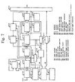
- Fig. 7 shows in block form a speech signal coding apparatus according to a fourth embodiment of the present invention. Those parts shown in Fig. 7 which are identical to those shown in Fig. 1 or 5 operate identically to those shown in Fig. 1 or 5, and will not be described in detail below.
- a spectral parameter and delay calculator 800 is supplied with an input speech signal x (n) and a past excitation signal e (n), and calculates spectral parameters ⁇ i in order to minimize a distortion expressed by the following equation (17) with respect to each delay T in a predetermined first delay search range.
- a combination of a first delay and a spectral parameter for minimizing the distortion E T is selected.
- the first delay is outputted to an adaptive code book circuit 710, and the spectral parameter ⁇ i is outputted to a spectral parameter quantizer 210.
- a drive signal calculator 810 is supplied with a speech signal divided into subframes from a subframe divider 120 and spectral parameters from the spectral parameter and delay calculator 800, calculates a predictive residual signal e (n) for a subframe length according to the following equation (18), and stores the calculated predictive residual signal e (n) as a drive signal:
- Fig. 8 shows in block form a speech signal coding apparatus according to a fifth embodiment of the present invention. Those parts shown in Fig. 8 which are identical to those shown in Fig. 1 operate identically to those shown in Fig. 1, and will not be described in detail below.
- a mode decision circuit 850 receives a weighted signal in each frame from an audio weighting circuit 230, and outputs mode decision information. In this embodiment, the following four modes are employed :
- a feature amount such as a pitch predictive gain, for example, of a present frame is used to decide a mode.
- a pitch predictive gain is calculated according to the following equations (19) ⁇ (21), for example: where T is an optimum delay for maximizing the pitch predictive gain.
- the pitch predictive gain is compared with a plurality of predetermined thresholds and classified into one of plural types of modes.
- a mode decision circuit 850 outputs the mode decision information to an adaptive code book circuit 860 and a multiplexer 400.
- the adaptive code book circuit 860 supplied with the mode decision information. If the mode decision information represents a predetermined mode, the adaptive code book circuit 860 operates in the same manner as the adaptive code book circuit 500 shown in Fig. 1, calculates a delay, and outputs the delay and an index indicative of the delay.
- the mode is decided as described above because while in the strong steady part of a vowel in the mode 3, the speech signal can be coded highly efficiently due to large pitch periodicity, the pitch periodicity is small and many errors tend to occur in the other modes.
- any coding according to an adaptive code book is not carried out in those modes in which the speech signal cannot be coded highly efficiently, so that the overall operation of the apparatus is made highly efficient.
- Fig. 9 shows in block form a speech signal coding apparatus according to a sixth embodiment of the present invention. Those parts shown in Fig. 9 which are identical to those shown in Fig. 3 or 8 operate identically to those shown in Fig. 3 or 8, and will not be described in detail below.
- an adaptive code book circuit 900 is supplied with mode decision information from a mode decision circuit 850. If the mode decision information represents a predetermined mode, the adaptive code book circuit 900 operates in the same manner as the adaptive code book circuit 600 shown in Fig. 3, calculates a delay, and outputs the delay and an index indicative of the delay.
- Fig. 10 shows in block form a speech signal coding apparatus according to a seventh embodiment of the present invention. Those parts shown in Fig. 10 which are identical to those shown in Fig. 5 or 8 operate identically to those shown in Fig. 5 or 8, and will not be described in detail below.
- an adaptive code book circuit 910 is supplied with mode decision information from a mode decision circuit 850. If the mode decision information represents a predetermined mode, the adaptive code book circuit 910 operates in the same manner as the adaptive code book circuit 710 shown in Fig. 5, calculates a delay, and outputs the delay and an index indicative of the delay.
- Fig. 11 shows in block form a speech signal coding apparatus according to an eighth embodiment of the present invention. Those parts shown in Fig. 11 which are identical to those shown in Fig. 7 or 8 operate identically to those shown in Fig. 7 or 8, and will not be described in detail below.
- an adaptive code book circuit 920 is supplied with mode decision information from a mode decision circuit 850. If the mode decision information represents a predetermined mode, the adaptive code book circuit 920 operates in the same manner as the adaptive code book circuit 710 shown in Fig. 7, calculates a delay, and outputs the delay and an index indicative of the delay.
- the excitation code book for the excitation quantizer may be of any of other known arrangements, e.g., a multistage arrangement or a sparse arrangement.
- the excitation quantizer searches the excitation code book.
- the excitation quantizer may search a plurality of multipulses having different positions and amplitudes.
- the amplitudes and positions of multipulses may be determined in order to minimize the following equation (22) : where g j , m j represent the amplitude and position of a jth multipulse, and k the number of multipulses.
- delays in an adaptive code book are determined with respect to a plurality of quantization candidates for spectral parameters, and the best of all combinations of the delays and the quantization candidates is selected.
- Spectral parameters and a first delay are simultaneously calculated, at least one second delay is calculated based on the first delay with respect to the plurality of quantization candidates for spectral parameters, and the best of all combinations of the second delay and the quantization candidates is selected.
- the above processing is carried out with respect to only a predetermined mode. Therefore, it is possible for the coding process to be less subject to effects of a pitch and to determine spectral parameters taking quantization and delays in an adaptive code book into account. Consequently, the coding process according to the present invention can maintain good sound quality even if the bit rate is lowered, as compared with the conventional systems.
Landscapes
- Engineering & Computer Science (AREA)
- Computational Linguistics (AREA)
- Signal Processing (AREA)
- Health & Medical Sciences (AREA)
- Audiology, Speech & Language Pathology (AREA)
- Human Computer Interaction (AREA)
- Physics & Mathematics (AREA)
- Acoustics & Sound (AREA)
- Multimedia (AREA)
- Compression, Expansion, Code Conversion, And Decoders (AREA)
Claims (16)
- Vorrichtung zum Codieren eines Sprachsignals, die folgendes aufweist:eine Spektrumsparameter-Berechnungseinheit (200) zum Bestimmen von spektralen Parametern aus einem eingegebenen Sprachsignal, zum Quantisieren der spektralen Parameter und zum Ausgeben einer Vielzahl von Quantisierungskandidaten;ein Adaptiv-Codebuch (500) zum Bestimmen von Verzögerungen in bezug auf jeden der von der Spektrumsparameter-Berechnungseinheit ausgegebenen Quantisierungskandidaten, zum Erzeugen eines Tonhöhenvorhersagesignals basierend auf einem vergangenen Erregungssignal für jede der Verzögerungen und zugehöriger Quantisierungskandidaten und zum Ausgeben eines Quantisierungskandidaten und einer Verzögerung, die eine minimale Verzerrung zwischen dem Sprachsignal und dem Tonhöhenvorhersagesignal liefern;einen Erregungsquantisierer (350) zum Quantisieren und Ausgeben des Erregungssignals des Sprachsignals; undeinen Verstärkungsquantisierer (365) zum Quantisieren und zum Ausgeben einer Verstärkung von wenigstens einem von dem Adaptiv-Codebuch und dem quantisierten Erregungssignal.
- Vorrichtung zum Codieren eines Sprachsignals, die folgendes aufweist:eine Spektrumsparameter-Berechnungseinheit (200) zum Bestimmen von spektralen Parametern aus einem eingegebenen Sprachsignal, zum Quantisieren der spektralen Parameter und zum Ausgeben einer Vielzahl von Quantisierungskandidaten;ein Adaptiv-Codebuch (600) zum Bestimmen einer Verzögerung, zum Erzeugen von Verzögerungskandidaten, die innerhalb eines vorbestimmten Verzögerungsbereichs existieren, zum Erzeugen eines unter Verwendung eines aus einem vergangenen Erregungssignal für einen Verzögerungskandidaten und einen Quantisierungskandidaten zugeschnittenen Signals berechneten Tonhöhenvorhersagesignals für jede aller Kombinationen zwischen jedem der Verzögerungskandidaten und jedem der Quantisierungskandidaten und zum Ausgeben einer optimalen Kombination zwischen einem Quantisierungskandidaten und einer Verzögerung, welche eine minimale Verzerrung zwischen dem eingegebenen Sprachsignal und dem quantisierten Erregungssignal liefert; undeinen Verstärkungsquantisierer (365) zum Quantisieren und zum Ausgeben einer Verstärkung von wenigstens einem von dem Adaptiv-Codebuch und dem quantisierten Erregungssignal.
- Vorrichtung zum Codieren eines Sprachsignals, die folgendes aufweist:eine Spektrumsparameter- und Verzögerungs-Berechnungseinheit (700) zum Berechnen von spektralen Parametern und einer ersten Verzögerung aus einem aus einem vergangenen Erregungssignal für eine Verzögerung und einem eingegebenen Sprachsignal zugeschnittenen Signal;einen Spektrumsparameter-Quantisierer (210) zum Quantisieren der spektralen Parameter und zum Ausgeben wenigstens eines Quantisierungskandidaten;ein Adaptiv-Codebuch (710) zum Bestimmen einer zweiten Verzögerung basierend auf der ersten Verzögerung, zum Berechnen wenigstens eines zur ersten Verzögerung benachbarten zweiten Verzögerungskandidaten, zum Erzeugen eines unter Verwendung eines aus einem vergangenen Erregungssignal für den zweiten Verzögerungskandidaten und den Quantisierungskandidaten zugeschnittenen Signals berechneten Tonhöhenvorhersagesignals für alle der wenigstens zwei Kombinationen zwischen jedem der zweiten Verzögerungskandidaten und jedem der Quantisierungskandidaten;einen Erregungsquantisierer (350) zum Quantisieren und zum Ausgeben des Erregungssignals des Sprachsignals; undeinen Verstärkungsquantisierer (365) zum Quantisieren und zum Ausgeben einer Verstärkung von wenigstens einem von dem Adaptiv-Codebuch und dem quantisierten Erregungssignal.
- Vorrichtung zum Codieren eines Sprachsignals, die folgendes aufweist:eine Spektrumsparameter- und Verzögerungs-Berechnungseinheit (800), damit ihr ein eingegebenes Sprachsignal zugeführt wird, zum gemeinsamen Berechnen von spektralen Parametern und einer ersten Verzögerung aus einem aus einem vergangenen Treibersignal für eine Verzögerung und dem eingegebenen Sprachsignal zugeschnittenen Signal;eine Treibersignal-Berechnungseinheit (810) zum Berechnen eines Treibersignals aus den spektralen Parametern und dem Sprachsignal;einem Spektrumsparameter-Quantisierer (210) zum Quantisieren der spektralen Parameter und zum Ausgeben wenigstens eines Quantisierungskandidaten;ein Adaptiv-Codebuch (710) zum Bestimmen einer zweiten Verzögerung basierend auf der ersten Verzögerung, zum Berechnen wenigstens eines zur ersten Verzögerung benachbarten zweiten Verzögerungskandidaten, zum Erzeugen eines unter Verwendung eines aus einem vergangenen Erregungssignal für den zweiten Verzögerungskandidaten und den Quantisierungskandidaten zugeschnittenen Signals berechneten Tonhöhenvorhersagesignals für alle der wenigstens zwei Kombinationen zwischen jedem der zweiten Verzögerungskandiaten und jedem der Quantisierungskandidaten;einen Erregungsquantisierer (350) zum Quantisieren und zum Ausgeben des Erregungssignals des Sprachsignals; undeinen Verstärkungsquantisierer (365) zum Quantisieren und zum Ausgeben einer Verstärkung von wenigstens einem von dem Adaptiv-Codebuch und dem quantisierten Erregungssignal.
- Vorrichtung nach Anspruch 1, die weiterhin folgendes aufweist:
eine Moden-Entscheidungseinheit zum Entscheiden über einen Mode eines eingegebenen Sprachsignals und zum Ausgeben von Moden-Entscheidungsinformation; und wobei die Vorrichtung betrieben wird, wenn die von der Moden-Entscheidungseinheit ausgegebene Moden-Entscheidungsinformation einen vorbestimmten Mode darstellt. - Vorrichtung nach Anspruch 2, die weiterhin folgendes aufweist:
eine Moden-Entscheidungseinheit zum Entscheiden über einen Mode eines eingegebenen Sprachsignals und zum Ausgeben von Moden-Entscheidungsinformation; und wobei die Vorrichtung betrieben wird, wenn die von der Moden-Entscheidungseinheit ausgegebene Moden-Entscheidungsinformation einen vorbestimmten Mode darstellt. - Vorrichtung nach Anspruch 3, die weiterhin folgendes aufweist:
eine Moden-Entscheidungseinheit zum Entscheiden über einen Mode eines eingegebenen Sprachsignals und zum Ausgeben von Moden-Entscheidungsinformation; und wobei die Vorrichtung betrieben wird, wenn die von der Moden-Entscheidungseinheit ausgegebene Moden-Entscheidungsinformation einen vorbestimmten Mode darstellt. - Vorrichtung nach Anspruch 4, die weiterhin folgendes aufweist:
eine Moden-Entscheidungseinheit zum Entscheiden über einen Mode eines eingegebenen Sprachsignals und zum Ausgeben von Moden-Entscheidungsinformation; und wobei die Vorrichtung betrieben wird, wenn die von der Moden-Entscheidungseinheit ausgegebene Moden-Entscheidungsinformation einen vorbestimmten Mode darstellt. - Verfahren zum Codieren eines Sprachsignals, das die folgenden Schritte aufweist:Bestimmen von spektralen Parametern aus einem eingegebenen Sprachsignal, Quantisieren der spektralen Parameter und Ausgeben einer Vielzahl von Quantisierungskandidaten; undBestimmen von Verzögerungen in bezug auf die Quantisierungskandidaten, Erzeugen eines Tonhöhenvorhersagesignals basierend auf einem vergangenen Erregungssignal für jede der Verzögerungen und jeden der zugehörigen Quantisierungskandidaten und Bestimmen eines Quantisierungskandidaten und einer Verzögerung, die eine minimale Verzerrung zwischen dem eingegebenen Sprachsignal und dem Tonhöhenvorhersagesignal liefern.
- Verfahren zum Codieren eines Sprachsignals, das die folgenden Schritte aufweist:Bestimmen von spektralen Parametern aus einem eingegebenen Sprachsignal, Quantisieren der spektralen Parameter und Ausgeben einer Vielzahl von Quantisierungskandidaten;Bestimmen einer Verzögerung, Erzeugen von Verzögerungskandidaten, die innerhalb eines vorbestimmten Verzögerungsbereichs existieren, Erzeugen eines unter Verwendung eines aus einem vergangenen Erregungssignal für einen Verzögerungskandidaten und einen Quantisierungskandidaten zugeschnittenen Signals berechneten Tonhöhenvorhersagesignals für jede aller Kombinationen zwischen jedem der Verzögerungskandidaten und jedem der Quantisierungskandidaten und Ausgeben einer optimalen Kombination zwischen einem Quantisierungskandidaten und einer Verzögerung, die eine minimale Verzerrung zwischen dem eingegebenen Sprachsignal und dem quantisierten Erregungssignal liefern.
- Verfahren zum Codieren eines Sprachsignals, das die folgenden Schritte aufweist:Berechnen von spektralen Parametern und einer ersten Verzögerung aus einem aus einem vergangenen Erregungssignal für eine Verzögerung und einem eingegebenen Sprachsignal zugeschnittenen Signal;Bestimmen von wenigstens einem Quantisierungskandidaten für die spektralen Parameter; undBerechnen von wenigstens einer zweiten Verzögerung basierend auf der ersten Verzögerung, Berechnen von wenigstens einem zur ersten Verzögerung benachbarten zweiten Verzögerungskandidaten, Erzeugen eines unter Verwendung eines aus einem vergangenen Erregungssignal für den zweiten Verzögerungskandidaten und den Quantisierungskandidaten zugeschnittenen Signals berechneten Tonhöhenvorhersagesignals für alle der wenigstens zwei Kombinationen zwischen jedem der zweiten Verzögerungskandidaten und jedem der Quantisierungskandidaten.
- Verfahren zum Codieren eines Sprachsignals, das die folgenden Schritte aufweist:Eingeben eines Sprachsignals, Berechnen von spektralen Parametern und einer ersten Verzögerung aus einem aus einem vergangenen Treibersignal für eine Verzögerung und dem eingegebenen Sprachsignal zugeschnittenen Signal;Berechnen eines Treibersignals aus den spektralen Parametern und dem Sprachsignal;Bestimmen von wenigstens einem Quantisierungskandidaten für die spektralen Parameter;Berechnen von wenigstens einer zweiten Verzögerung basierend auf der ersten Verzögerung, Berechnen von wenigstens einem zur ersten Verzögerung benachbarten zweiten Verzögerungskandidaten, Erzeugen eines unter Verwendung eines aus einem vergangenen Erregungssignal für den zweiten Verzögerungskandidaten und den Quantisierungskandidaten zugeschnittenen Signals berechneten Tonhöhenvorhersagesignals für alle der wenigstens zwei Kombinationen zwischen jedem der zweiten Verzögerungskandidaten und jedem der Quantisierungskandidaten.
- Verfahren nach Anspruch 9, das weiterhin die folgenden Schritte aufweist:zuerst Entscheiden über einen Mode eines eingegebenen Sprachsignals;Ausführen des Verfahrens nach Anspruch 9, wenn die von der Moden-Entscheidungseinheit ausgegebene Moden-Entscheidungsinformation einen vorbestimmten Mode darstellt.
- Verfahren nach Anspruch 10, das weiterhin die folgenden Schritte aufweist:zuerst Entscheiden über einen Mode eines eingegebenen Sprachsignals;Ausführen des Verfahrens nach Anspruch 10, wenn die von der Moden-Entscheidungseinheit ausgegebene Moden-Entscheidungsinformation einen vorbestimmten Mode darstellt.
- Verfahren nach Anspruch 11, das weiterhin die folgenden Schritte aufweist:zuerst Entscheiden über einen Mode eines eingegebenen Sprachsignals;Ausführen des Verfahrens nach Anspruch 11, wenn die von der Moden-Entscheidungseinheit ausgegebene Moden-Entscheidungsinformation einen vorbestimmten Mode darstellt.
- Verfahren nach Anspruch 12, das weiterhin die folgenden Schritte aufweist:zuerst Entscheiden über einen Mode eines eingegebenen Sprachsignals;Ausführen des Verfahrens nach Anspruch 12, wenn die von der Moden-Entscheidungseinheit ausgegebene Moden-Entscheidungsinformation einen vorbestimmten Mode darstellt.
Applications Claiming Priority (3)
| Application Number | Priority Date | Filing Date | Title |
|---|---|---|---|
| JP133372/95 | 1995-05-31 | ||
| JP13337295 | 1995-05-31 | ||
| JP13337295A JP3308764B2 (ja) | 1995-05-31 | 1995-05-31 | 音声符号化装置 |
Publications (3)
| Publication Number | Publication Date |
|---|---|
| EP0745972A2 EP0745972A2 (de) | 1996-12-04 |
| EP0745972A3 EP0745972A3 (de) | 1998-09-02 |
| EP0745972B1 true EP0745972B1 (de) | 2001-08-29 |
Family
ID=15103195
Family Applications (1)
| Application Number | Title | Priority Date | Filing Date |
|---|---|---|---|
| EP96108599A Expired - Lifetime EP0745972B1 (de) | 1995-05-31 | 1996-05-30 | Verfahren und Vorrichtung zur Sprachkodierung |
Country Status (5)
| Country | Link |
|---|---|
| US (1) | US5884252A (de) |
| EP (1) | EP0745972B1 (de) |
| JP (1) | JP3308764B2 (de) |
| CA (1) | CA2177226C (de) |
| DE (1) | DE69614761T2 (de) |
Families Citing this family (8)
| Publication number | Priority date | Publication date | Assignee | Title |
|---|---|---|---|---|
| US6233550B1 (en) | 1997-08-29 | 2001-05-15 | The Regents Of The University Of California | Method and apparatus for hybrid coding of speech at 4kbps |
| JP3166697B2 (ja) * | 1998-01-14 | 2001-05-14 | 日本電気株式会社 | 音声符号化・復号装置及びシステム |
| US6691084B2 (en) | 1998-12-21 | 2004-02-10 | Qualcomm Incorporated | Multiple mode variable rate speech coding |
| JP4108317B2 (ja) | 2001-11-13 | 2008-06-25 | 日本電気株式会社 | 符号変換方法及び装置とプログラム並びに記憶媒体 |
| JP4263412B2 (ja) * | 2002-01-29 | 2009-05-13 | 富士通株式会社 | 音声符号変換方法 |
| JP2006145712A (ja) * | 2004-11-18 | 2006-06-08 | Pioneer Electronic Corp | オーディオデータ補間装置 |
| AU2014211539B2 (en) * | 2013-01-29 | 2017-04-20 | Fraunhofer-Gesellschaft Zur Foerderung Der Angewandten Forschung E.V. | Low-complexity tonality-adaptive audio signal quantization |
| CN111312265B (zh) * | 2014-01-15 | 2023-04-28 | 三星电子株式会社 | 对线性预测编码系数进行量化的加权函数确定装置和方法 |
Family Cites Families (20)
| Publication number | Priority date | Publication date | Assignee | Title |
|---|---|---|---|---|
| JPS6262399A (ja) * | 1985-09-13 | 1987-03-19 | 株式会社日立製作所 | 音声高能率符号化方式 |
| JPH0761044B2 (ja) * | 1986-07-28 | 1995-06-28 | 日本電信電話株式会社 | 音声符号化法 |
| US5077798A (en) * | 1988-09-28 | 1991-12-31 | Hitachi, Ltd. | Method and system for voice coding based on vector quantization |
| US5091945A (en) * | 1989-09-28 | 1992-02-25 | At&T Bell Laboratories | Source dependent channel coding with error protection |
| CA2027705C (en) * | 1989-10-17 | 1994-02-15 | Masami Akamine | Speech coding system utilizing a recursive computation technique for improvement in processing speed |
| EP0443548B1 (de) * | 1990-02-22 | 2003-07-23 | Nec Corporation | Sprachcodierer |
| JP3114197B2 (ja) * | 1990-11-02 | 2000-12-04 | 日本電気株式会社 | 音声パラメータ符号化方法 |
| JP3151874B2 (ja) * | 1991-02-26 | 2001-04-03 | 日本電気株式会社 | 音声パラメータ符号化方式および装置 |
| JP3254687B2 (ja) * | 1991-02-26 | 2002-02-12 | 日本電気株式会社 | 音声符号化方式 |
| JP2776050B2 (ja) * | 1991-02-26 | 1998-07-16 | 日本電気株式会社 | 音声符号化方式 |
| JP3026461B2 (ja) * | 1991-04-01 | 2000-03-27 | 日本電信電話株式会社 | 音声のピッチ予測符号化法 |
| US5396576A (en) * | 1991-05-22 | 1995-03-07 | Nippon Telegraph And Telephone Corporation | Speech coding and decoding methods using adaptive and random code books |
| JP3143956B2 (ja) * | 1991-06-27 | 2001-03-07 | 日本電気株式会社 | 音声パラメータ符号化方式 |
| JPH05265496A (ja) * | 1992-03-18 | 1993-10-15 | Hitachi Ltd | 複数のコードブックを有する音声符号化方法 |
| JP2746039B2 (ja) * | 1993-01-22 | 1998-04-28 | 日本電気株式会社 | 音声符号化方式 |
| JP2800618B2 (ja) * | 1993-02-09 | 1998-09-21 | 日本電気株式会社 | 音声パラメータ符号化方式 |
| US5598504A (en) * | 1993-03-15 | 1997-01-28 | Nec Corporation | Speech coding system to reduce distortion through signal overlap |
| IT1270439B (it) * | 1993-06-10 | 1997-05-05 | Sip | Procedimento e dispositivo per la quantizzazione dei parametri spettrali in codificatori numerici della voce |
| JP2658816B2 (ja) * | 1993-08-26 | 1997-09-30 | 日本電気株式会社 | 音声のピッチ符号化装置 |
| CA2137756C (en) * | 1993-12-10 | 2000-02-01 | Kazunori Ozawa | Voice coder and a method for searching codebooks |
-
1995
- 1995-05-31 JP JP13337295A patent/JP3308764B2/ja not_active Expired - Fee Related
-
1996
- 1996-05-23 CA CA002177226A patent/CA2177226C/en not_active Expired - Fee Related
- 1996-05-30 EP EP96108599A patent/EP0745972B1/de not_active Expired - Lifetime
- 1996-05-30 DE DE69614761T patent/DE69614761T2/de not_active Expired - Lifetime
- 1996-05-31 US US08/657,660 patent/US5884252A/en not_active Expired - Lifetime
Also Published As
| Publication number | Publication date |
|---|---|
| CA2177226A1 (en) | 1996-12-01 |
| EP0745972A3 (de) | 1998-09-02 |
| JPH08328597A (ja) | 1996-12-13 |
| JP3308764B2 (ja) | 2002-07-29 |
| DE69614761T2 (de) | 2002-06-20 |
| CA2177226C (en) | 2000-10-03 |
| EP0745972A2 (de) | 1996-12-04 |
| US5884252A (en) | 1999-03-16 |
| DE69614761D1 (de) | 2001-10-04 |
Similar Documents
| Publication | Publication Date | Title |
|---|---|---|
| EP0422232B1 (de) | Stimmenkodierer | |
| US6345248B1 (en) | Low bit-rate speech coder using adaptive open-loop subframe pitch lag estimation and vector quantization | |
| EP0802524B1 (de) | Sprachkodierer | |
| EP0409239A2 (de) | Verfahren zur Sprachkodierung und -dekodierung | |
| EP1093116A1 (de) | Autokorrelation basierte Suchschleife für CELP Sprachkodierer | |
| EP0957472B1 (de) | Vorrichtung zur Sprachkodierung und -dekodierung | |
| JPH0990995A (ja) | 音声符号化装置 | |
| EP1162604B1 (de) | Sprachkodierer hoher Qualität mit niedriger Bitrate | |
| US6581031B1 (en) | Speech encoding method and speech encoding system | |
| US7680669B2 (en) | Sound encoding apparatus and method, and sound decoding apparatus and method | |
| EP0810584A2 (de) | Signalkodierer | |
| EP0745972B1 (de) | Verfahren und Vorrichtung zur Sprachkodierung | |
| EP0557940A2 (de) | Sprachkodierungsystem | |
| EP0696793A2 (de) | Sprachkodierer | |
| JP3003531B2 (ja) | 音声符号化装置 | |
| EP1154407A2 (de) | Positionsinformationskodierung in einem Multipuls-Anregungs-Sprachkodierer | |
| JP3153075B2 (ja) | 音声符号化装置 | |
| JP3192051B2 (ja) | 音声符号化装置 | |
| JPH08320700A (ja) | 音声符号化装置 | |
| JP3092654B2 (ja) | 信号符号化装置 | |
| JPH0511799A (ja) | 音声符号化方式 | |
| JPH08194499A (ja) | 音声符号化装置 | |
| JP3144244B2 (ja) | 音声符号化装置 | |
| JPH09319399A (ja) | 音声符号化装置 |
Legal Events
| Date | Code | Title | Description |
|---|---|---|---|
| PUAI | Public reference made under article 153(3) epc to a published international application that has entered the european phase |
Free format text: ORIGINAL CODE: 0009012 |
|
| AK | Designated contracting states |
Kind code of ref document: A2 Designated state(s): DE FR GB IT NL SE |
|
| PUAL | Search report despatched |
Free format text: ORIGINAL CODE: 0009013 |
|
| AK | Designated contracting states |
Kind code of ref document: A3 Designated state(s): DE FR GB IT NL SE |
|
| 17P | Request for examination filed |
Effective date: 19981228 |
|
| RIC1 | Information provided on ipc code assigned before grant |
Free format text: 7G 10L 19/06 A |
|
| GRAG | Despatch of communication of intention to grant |
Free format text: ORIGINAL CODE: EPIDOS AGRA |
|
| RIC1 | Information provided on ipc code assigned before grant |
Free format text: 7G 10L 19/06 A |
|
| 17Q | First examination report despatched |
Effective date: 20001227 |
|
| GRAG | Despatch of communication of intention to grant |
Free format text: ORIGINAL CODE: EPIDOS AGRA |
|
| GRAH | Despatch of communication of intention to grant a patent |
Free format text: ORIGINAL CODE: EPIDOS IGRA |
|
| GRAH | Despatch of communication of intention to grant a patent |
Free format text: ORIGINAL CODE: EPIDOS IGRA |
|
| GRAA | (expected) grant |
Free format text: ORIGINAL CODE: 0009210 |
|
| AK | Designated contracting states |
Kind code of ref document: B1 Designated state(s): DE FR GB IT NL SE |
|
| REF | Corresponds to: |
Ref document number: 69614761 Country of ref document: DE Date of ref document: 20011004 |
|
| REG | Reference to a national code |
Ref country code: GB Ref legal event code: IF02 |
|
| ET | Fr: translation filed | ||
| PLBE | No opposition filed within time limit |
Free format text: ORIGINAL CODE: 0009261 |
|
| STAA | Information on the status of an ep patent application or granted ep patent |
Free format text: STATUS: NO OPPOSITION FILED WITHIN TIME LIMIT |
|
| 26N | No opposition filed | ||
| PGFP | Annual fee paid to national office [announced via postgrant information from national office to epo] |
Ref country code: NL Payment date: 20090517 Year of fee payment: 14 |
|
| PGFP | Annual fee paid to national office [announced via postgrant information from national office to epo] |
Ref country code: SE Payment date: 20090512 Year of fee payment: 14 Ref country code: IT Payment date: 20090521 Year of fee payment: 14 |
|
| REG | Reference to a national code |
Ref country code: NL Ref legal event code: V1 Effective date: 20101201 |
|
| EUG | Se: european patent has lapsed | ||
| PG25 | Lapsed in a contracting state [announced via postgrant information from national office to epo] |
Ref country code: NL Free format text: LAPSE BECAUSE OF NON-PAYMENT OF DUE FEES Effective date: 20101201 Ref country code: IT Free format text: LAPSE BECAUSE OF NON-PAYMENT OF DUE FEES Effective date: 20100530 Ref country code: SE Free format text: LAPSE BECAUSE OF NON-PAYMENT OF DUE FEES Effective date: 20100531 |
|
| REG | Reference to a national code |
Ref country code: FR Ref legal event code: PLFP Year of fee payment: 20 |
|
| PGFP | Annual fee paid to national office [announced via postgrant information from national office to epo] |
Ref country code: DE Payment date: 20150527 Year of fee payment: 20 Ref country code: GB Payment date: 20150527 Year of fee payment: 20 |
|
| PGFP | Annual fee paid to national office [announced via postgrant information from national office to epo] |
Ref country code: FR Payment date: 20150508 Year of fee payment: 20 |
|
| REG | Reference to a national code |
Ref country code: DE Ref legal event code: R071 Ref document number: 69614761 Country of ref document: DE |
|
| REG | Reference to a national code |
Ref country code: GB Ref legal event code: PE20 Expiry date: 20160529 |
|
| PG25 | Lapsed in a contracting state [announced via postgrant information from national office to epo] |
Ref country code: GB Free format text: LAPSE BECAUSE OF EXPIRATION OF PROTECTION Effective date: 20160529 |