EP0744987B1 - A method for removing and preventing emissions into the atmosphere of carbon dioxide (co 2) from exhaust gases from heat engines - Google Patents
A method for removing and preventing emissions into the atmosphere of carbon dioxide (co 2) from exhaust gases from heat engines Download PDFInfo
- Publication number
- EP0744987B1 EP0744987B1 EP95910020A EP95910020A EP0744987B1 EP 0744987 B1 EP0744987 B1 EP 0744987B1 EP 95910020 A EP95910020 A EP 95910020A EP 95910020 A EP95910020 A EP 95910020A EP 0744987 B1 EP0744987 B1 EP 0744987B1
- Authority
- EP
- European Patent Office
- Prior art keywords
- gas
- absorption
- exhaust gas
- passed
- exhaust
- Prior art date
- Legal status (The legal status is an assumption and is not a legal conclusion. Google has not performed a legal analysis and makes no representation as to the accuracy of the status listed.)
- Expired - Lifetime
Links
- 239000007789 gas Substances 0.000 title claims abstract description 141
- CURLTUGMZLYLDI-UHFFFAOYSA-N Carbon dioxide Chemical compound O=C=O CURLTUGMZLYLDI-UHFFFAOYSA-N 0.000 title claims abstract description 112
- 239000001569 carbon dioxide Substances 0.000 title claims abstract description 93
- 229910002092 carbon dioxide Inorganic materials 0.000 title claims abstract description 93
- 238000000034 method Methods 0.000 title claims abstract description 25
- 238000010521 absorption reaction Methods 0.000 claims abstract description 54
- 239000007788 liquid Substances 0.000 claims abstract description 33
- VNWKTOKETHGBQD-UHFFFAOYSA-N methane Chemical compound C VNWKTOKETHGBQD-UHFFFAOYSA-N 0.000 claims abstract description 20
- 238000011084 recovery Methods 0.000 claims abstract description 18
- 238000004519 manufacturing process Methods 0.000 claims abstract description 11
- 239000003345 natural gas Substances 0.000 claims abstract description 10
- 230000006835 compression Effects 0.000 claims abstract description 7
- 238000007906 compression Methods 0.000 claims abstract description 7
- 239000012528 membrane Substances 0.000 claims description 17
- 238000010438 heat treatment Methods 0.000 claims description 5
- HZAXFHJVJLSVMW-UHFFFAOYSA-N 2-Aminoethan-1-ol Chemical compound NCCO HZAXFHJVJLSVMW-UHFFFAOYSA-N 0.000 description 11
- 238000002485 combustion reaction Methods 0.000 description 10
- 238000004064 recycling Methods 0.000 description 9
- 238000012856 packing Methods 0.000 description 8
- 238000000926 separation method Methods 0.000 description 7
- 150000001412 amines Chemical class 0.000 description 5
- 239000000446 fuel Substances 0.000 description 5
- 238000010248 power generation Methods 0.000 description 5
- XLYOFNOQVPJJNP-UHFFFAOYSA-N water Substances O XLYOFNOQVPJJNP-UHFFFAOYSA-N 0.000 description 5
- 238000013461 design Methods 0.000 description 4
- 230000000694 effects Effects 0.000 description 4
- 238000002347 injection Methods 0.000 description 4
- 239000007924 injection Substances 0.000 description 4
- 238000009434 installation Methods 0.000 description 4
- 239000013535 sea water Substances 0.000 description 4
- QVGXLLKOCUKJST-UHFFFAOYSA-N atomic oxygen Chemical compound [O] QVGXLLKOCUKJST-UHFFFAOYSA-N 0.000 description 3
- 238000006243 chemical reaction Methods 0.000 description 3
- 230000005611 electricity Effects 0.000 description 3
- 238000005516 engineering process Methods 0.000 description 3
- 238000010304 firing Methods 0.000 description 3
- 239000001301 oxygen Substances 0.000 description 3
- 229910052760 oxygen Inorganic materials 0.000 description 3
- 239000000126 substance Substances 0.000 description 3
- 239000004215 Carbon black (E152) Substances 0.000 description 2
- RAHZWNYVWXNFOC-UHFFFAOYSA-N Sulphur dioxide Chemical compound O=S=O RAHZWNYVWXNFOC-UHFFFAOYSA-N 0.000 description 2
- 239000003245 coal Substances 0.000 description 2
- 238000009826 distribution Methods 0.000 description 2
- 239000002737 fuel gas Substances 0.000 description 2
- 229930195733 hydrocarbon Natural products 0.000 description 2
- 150000002430 hydrocarbons Chemical class 0.000 description 2
- 239000000203 mixture Substances 0.000 description 2
- 239000003208 petroleum Substances 0.000 description 2
- 230000009467 reduction Effects 0.000 description 2
- 229920006395 saturated elastomer Polymers 0.000 description 2
- 238000012546 transfer Methods 0.000 description 2
- 239000002918 waste heat Substances 0.000 description 2
- UHOVQNZJYSORNB-UHFFFAOYSA-N Benzene Chemical compound C1=CC=CC=C1 UHOVQNZJYSORNB-UHFFFAOYSA-N 0.000 description 1
- XSQUKJJJFZCRTK-UHFFFAOYSA-N Urea Chemical compound NC(N)=O XSQUKJJJFZCRTK-UHFFFAOYSA-N 0.000 description 1
- 150000001298 alcohols Chemical class 0.000 description 1
- 230000015572 biosynthetic process Effects 0.000 description 1
- 239000004202 carbamide Substances 0.000 description 1
- 230000015556 catabolic process Effects 0.000 description 1
- 230000005465 channeling Effects 0.000 description 1
- 150000001875 compounds Chemical class 0.000 description 1
- 239000000356 contaminant Substances 0.000 description 1
- 230000003247 decreasing effect Effects 0.000 description 1
- 238000006731 degradation reaction Methods 0.000 description 1
- 230000009977 dual effect Effects 0.000 description 1
- 238000004134 energy conservation Methods 0.000 description 1
- 238000005265 energy consumption Methods 0.000 description 1
- 239000000835 fiber Substances 0.000 description 1
- 238000005187 foaming Methods 0.000 description 1
- 230000005484 gravity Effects 0.000 description 1
- 239000005431 greenhouse gas Substances 0.000 description 1
- 230000002209 hydrophobic effect Effects 0.000 description 1
- 239000007791 liquid phase Substances 0.000 description 1
- 238000012423 maintenance Methods 0.000 description 1
- 239000000463 material Substances 0.000 description 1
- 239000002184 metal Substances 0.000 description 1
- 229920000515 polycarbonate Polymers 0.000 description 1
- 239000004417 polycarbonate Substances 0.000 description 1
- 239000011148 porous material Substances 0.000 description 1
- 238000012545 processing Methods 0.000 description 1
- 238000000746 purification Methods 0.000 description 1
- 238000010791 quenching Methods 0.000 description 1
- 230000000171 quenching effect Effects 0.000 description 1
- 239000002994 raw material Substances 0.000 description 1
- 230000002441 reversible effect Effects 0.000 description 1
- 150000003839 salts Chemical class 0.000 description 1
- 239000007787 solid Substances 0.000 description 1
- 239000002904 solvent Substances 0.000 description 1
- 239000004291 sulphur dioxide Substances 0.000 description 1
- 235000010269 sulphur dioxide Nutrition 0.000 description 1
- 238000012360 testing method Methods 0.000 description 1
- 239000010409 thin film Substances 0.000 description 1
Images



Classifications
-
- B—PERFORMING OPERATIONS; TRANSPORTING
- B01—PHYSICAL OR CHEMICAL PROCESSES OR APPARATUS IN GENERAL
- B01D—SEPARATION
- B01D53/00—Separation of gases or vapours; Recovering vapours of volatile solvents from gases; Chemical or biological purification of waste gases, e.g. engine exhaust gases, smoke, fumes, flue gases, aerosols
- B01D53/22—Separation of gases or vapours; Recovering vapours of volatile solvents from gases; Chemical or biological purification of waste gases, e.g. engine exhaust gases, smoke, fumes, flue gases, aerosols by diffusion
- B01D53/229—Integrated processes (Diffusion and at least one other process, e.g. adsorption, absorption)
-
- B—PERFORMING OPERATIONS; TRANSPORTING
- B01—PHYSICAL OR CHEMICAL PROCESSES OR APPARATUS IN GENERAL
- B01D—SEPARATION
- B01D53/00—Separation of gases or vapours; Recovering vapours of volatile solvents from gases; Chemical or biological purification of waste gases, e.g. engine exhaust gases, smoke, fumes, flue gases, aerosols
- B01D53/14—Separation of gases or vapours; Recovering vapours of volatile solvents from gases; Chemical or biological purification of waste gases, e.g. engine exhaust gases, smoke, fumes, flue gases, aerosols by absorption
- B01D53/1456—Removing acid components
- B01D53/1475—Removing carbon dioxide
-
- Y—GENERAL TAGGING OF NEW TECHNOLOGICAL DEVELOPMENTS; GENERAL TAGGING OF CROSS-SECTIONAL TECHNOLOGIES SPANNING OVER SEVERAL SECTIONS OF THE IPC; TECHNICAL SUBJECTS COVERED BY FORMER USPC CROSS-REFERENCE ART COLLECTIONS [XRACs] AND DIGESTS
- Y02—TECHNOLOGIES OR APPLICATIONS FOR MITIGATION OR ADAPTATION AGAINST CLIMATE CHANGE
- Y02C—CAPTURE, STORAGE, SEQUESTRATION OR DISPOSAL OF GREENHOUSE GASES [GHG]
- Y02C20/00—Capture or disposal of greenhouse gases
- Y02C20/40—Capture or disposal of greenhouse gases of CO2
Definitions
- the present invention concerns the removal of carbon dioxide (CO 2 ) which is obtained from the combustion of hydrocarbon gases.
- CO 2 carbon dioxide
- One aspect of the invention concerns the removal of CO 2 from exhaust gases from heat engines, especially when such equipment is employed on offshore installations for the production and/or processing of oil and/or gas.
- a second aspect of the invention concerns the removal of CO 2 which is obtained from the combustion of natural gas in a gas turbine on an offshore oil/gas installation.
- CO 2 removal process which is intended for use in offshore installations.
- the most crucial constraint is that space and weight are very expensive commodities offshore, and the equipment therefore has to be as compact and light weight as possible.
- the CO 2 removal process must be installed in such a manner that maintenance of the separation unit does not interfere with the availability of the oil production process on the platform.
- the prospects for the disposal of pure CO 2 from offshore installations are good.
- CO 2 can be compressed and injected either into deep sea water, aquifers, depleted oil/gas reservoirs or into reservoirs which are still in production. The latter can result in enhanced oil recovery.
- the present invention concerns a method for removing and preventing emissions of carbon dioxide (CO 2 ) into the atmosphere from exhaust gases from gas turbines, installed on offshore platforms for the production of oil and/or gas.
- the invention is comprising the following steps:
- the invention is characterized in that approximately 40% of the exhaust gas is recycled to the compressor air inlet for the said gas turbine before the exhaust gas is passed to the absorption stage (c).
- the power generation concepts have been evaluated in order to find the concept which constitutes the best possible combination of the following factors; low exhaust gas flow, high CO 2 concentration, high efficiency and low weight.
- a combined cycle with recycling of 40% of the volume of the exhaust gas back to the inlet of the compressor is the most suitable amongst the concepts studied for the removal of CO 2 .
- the object of this invention has been to evaluate the use of the existing power generation concept for offshore separation of CO 2 from exhaust gas.
- the basis of these calculations has been an LM2500PE gas turbine, since this turbine is the most commonly used in the Norwegian sector of the North Sea.
- the fuel gas is a typical North Sea natural gas with a lower heating value of 47.6 MJ/kg. This fuel gas produces approximately 2.5 kg of CO 2 per Sm 3 of natural gas, assuming complete combustion.
- Gas turbine exhaust is not particularly suitable for recovery of CO 2 due to a typical excess air ratio in the range of 3-3.5, which results in a CO 2 concentration of only 3 - 3.5 mol%.
- the main objective of this invention has therefore been to find a process which will produce a lower exhaust gas volume and/or a higher CO 2 content than conventional aero-derivative gas turbines.
- the ECONAMINE FG process was developed in order to remove relatively low concentrations of CO 2 , typically 3-10 vol%, from low pressure gases with a high oxygen content.
- the solvent chosen for absorption is monoethanolamine (MEA) due to its ability to absorb high CO 2 volumes per MEA volume. Recoveries between 85% and 95% of CO 2 present in exhaust gases at atmospheric pressure are possible, depending on the CO 2 content of the feed gas.
- gas absorption membranes have also been employed for removal of CO 2 from exhaust gases, and this technology has already been tested for the removal of sulphur dioxide.
- Gas absorption membranes are used as contacting devices between a gas and a liquid flow. The separation is caused by the presence of an absorption liquid (MEA) on one side of the membrane which selectively removes certain components from the gas flow from the other side of the membrane.
- MEA absorption liquid
- CO 2 is absorbed by MEA in the temperature range 20-70°C, it then enters the stripping column in which CO 2 is released from MEA in the temperature range of 120-150°C. CO 2 is then compressed for injection, and MEA flows back to the absorption unit.
- the invention has been tested by removing CO 2 from exhaust gases of four GE LM2500PE gas turbines installed on a typical gas compressor platform.
- Fluor Daniel's ECONAMINE FG process was used to recover CO 2 from atmospheric exhaust gas.
- the plant was designed to remove CO 2 from 60% of the total exhaust gas flow.
- the rest of the exhaust gas is recycled to the gas turbine air compressor. This results in 1054 tons/day of recovered CO 2 based on four turbines.
- CO 2 is then compressed and sent to a subterranean reservoir or to another non-atmospheric destination. This treated exhaust gas is then vented to the atmosphere.
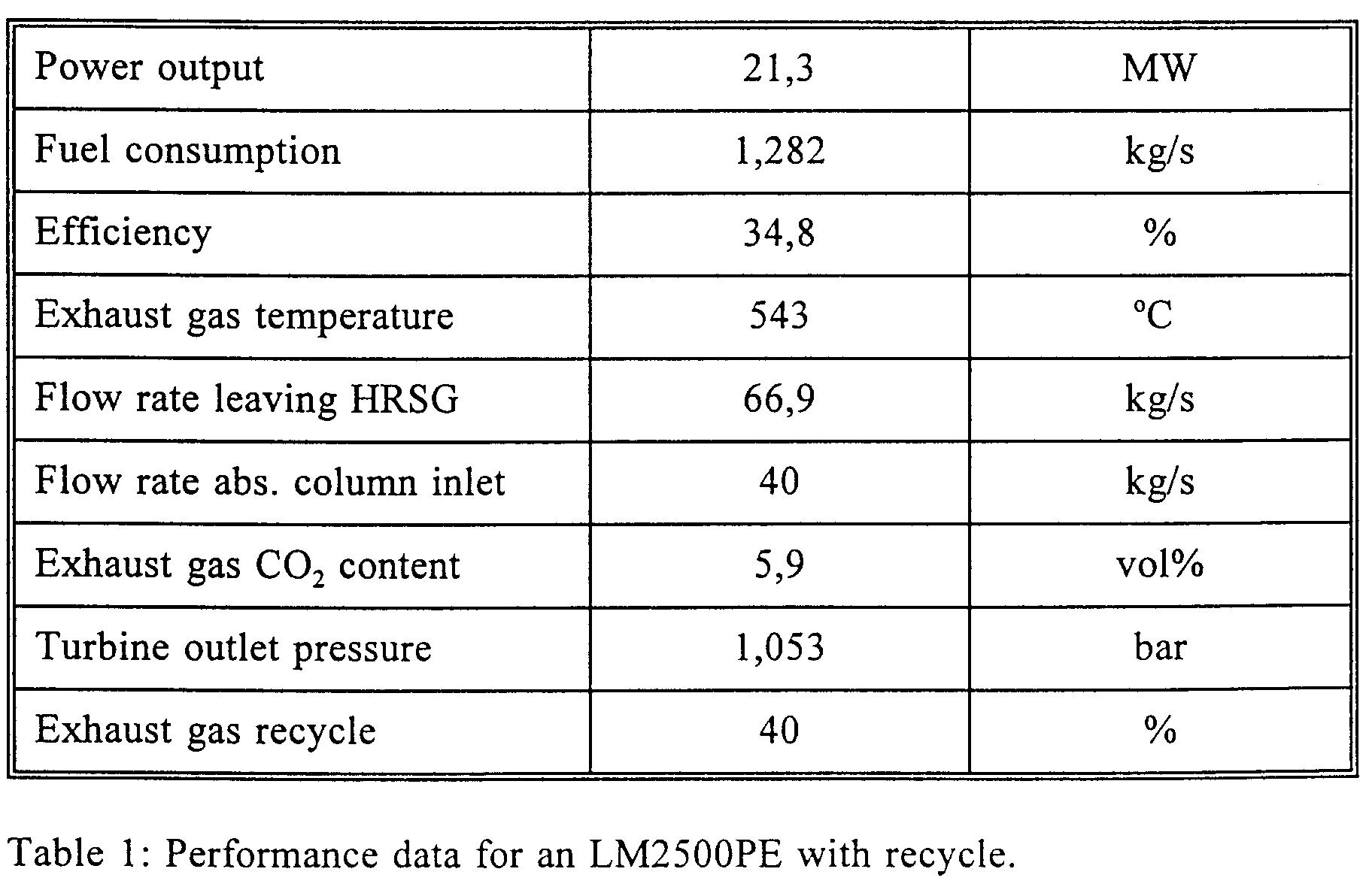
- the fuel consumption is 1.282 kg/s with lower heating value of 47562 KJ/kg and a composition as for an average North Sea gas.
- HRSG heat recovery steam generator
- the HRSG is designed for steam production at two pressure levels (40 and 4 bar).
- High pressure steam is expanded through a steam turbine, the condensate leaving the steam turbine is returned to the feed-water preheater and used in the process.
- the steam turbine is coupled via a gear to an electrical generator which provides the absorption and compression unit with electricity.
- the steam turbine produces approximately 3 MW of "surplus" energy per gas turbine which can be utilized for other purposes on the platform.
- the low pressure steam is used to heat the stripping column reboiler.
- the energy consumption in the reboiler is determined by the characteristics of the absorption chemical.
- the gas turbine is operated with recycling of exhaust gas.
- the exhaust gas leaving the HRSG is cooled to 30°C, and 40% of the total volume is recycled and mixed with fresh air between the air filter and the compressor inlet.
- the principal limitation of recycling is the O 2 content of the combustion air. Problems with instability and quenching of the flame may occur if the O 2 content is too low.
- 40% recycling for an LM2500 implies 16.5 mol% O 2 in the combustion air. According to the flammability limits, this should be on the conservative side.
- the molecular weight of air flowing through the compressor increases slightly when the exhaust gas is recycled, but this effect is not regarded as significant.
- Performance data for an LM2500PE are given in table 1.
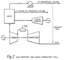
- a schematic outline of the process is shown in fig. 2.
- the fuel energy supplied to each gas turbine is 61.0 MW based on the lower heating value.
- the distribution of supplied fuel energy for four LM2500PE's is shown in table 2.
- the overall net efficiency for electrical power generation is 45.5%.
- the fuel energy utilization is 67%.
- the net efficiency for a simple cycle LM2500 is 35.4%.
- the reaction is reversible and the equilibrium can be altered by altering the temperature.
- CO 2 is absorbed by an absorption medium in the temperature range of 20-70°C , and is released from MEA in the temperature range of 120-150°C .
- the exhaust gas from the heat recovery and power generation unit passes through an exhaust gas cooler and an exhaust gas blower before entering an absorption tower.
- an absorption column Through the absorption column, the CO 2 content of the exhaust gas is reduced by means of a chemical reaction with the amine.
- the size of the absorption tower can be reduced by utilizing advanced technology such as structured packings or gas absorption membranes.
- the CO 2 enriched MEA is passed to a stripper where the CO 2 is released at temperatures of 120 - 150°C. Degradation of the absorption chemical will occur due to the formation of heat stable salts and other short chain compounds. These contaminants are removed in the MEA purification unit which is in operation for only a short time.
- Gas absorption membranes are membranes which are employed as contact devices between a gas and a liquid flow.
- the separation is caused by the presence of an absorption liquid on one side of the membrane which selectively removes certain components from the gas flow on the other side of the membrane.
- the membrane is intended to provide a contacting area which prevents mixing of the gas and the absorption liquid.
- the membrane should be highly permeable to the component which is required to be removed.
- the selectivity in the separation process is derived from the absorption liquid. A highly selective separation can be achieved through an appropriate choice of the absorption liquid.
- Fig. 3 illustrates the principle for the removal of CO 2 from exhaust gases.
- the use of gas absorption membranes has several advantages over conventional contacting devices such as packed columns:
- the conventional stripping column can be replaced by a rotating gas/liquid contactor which is called HIGEE.
- HIGEE rotating gas/liquid contactor
- the Higee unit consists of a rotor containing the packing arranged in a torus, and a stationary housing. Two seals are incorporated, one shaft seal between the rotating shaft and the housing, and the other between the rotor and the gas/vapor outlet duct in order to prevent gas or vapor from bypassing the rotating packing.
- the Higee unit is illustrated in fig. 4.
- Gas enters the housing via a tangential nozzle and flows inwards through the rotating packing. There it comes into intimate contact with the liquid, which has been distributed at the "eye" of the packing, and is forced outwards by the centrifugal forces.
- the gas (vapor) leaves the nozzle centred on the axis of the machine, while the droplets of liquid leaving the rotor impinge on the rotor's walls (or internals) and the liquid is drained from the housing.
- the CO 2 resulting from the separation process can be disposed of in several ways:
- Liquid or solid CO 2 can be absorbed in sea water.
- the solubility of CO 2 in sea water increases with decreasing temperatures.
- the ecological effects of CO 2 disposal in the ocean are still not sufficiently well investigated and understood.
- CO 2 By injecting CO 2 into petroleum reservoirs, the oil recovery rate can be increased. CO 2 will be mixed with some of the oil which is present, and this mixture of CO 2 and oil will displace oil which cannot be displaced by traditional water injection.
- CO 2 in the production gas gradually will increase. If the gas is to be exported, the increase in carbon dioxide may affect the quality and saleability of the gas.
- Disposal of CO 2 in depleted reservoirs is considered to be safe as long as the injection pressure is below the original reservoir pressure. If the reservoir is filled with water, the possibility of CO 2 escaping the reservoir is greater.
- Carbon dioxide is used as a raw material for the chemical industry, especially for the production of urea, polycarbonate and alcohols. However, this does not represent an alternative to the disposal of large amounts of CO 2 .
- the main objective which must be fulfilled by the power generation unit is that the net power output from an LM2500 simple cycle gas turbine (approximately 21 MW) should be available regardless of the power and heat requirements for the CO 2 removal process.
- the HRSG has to supply a steam turbine with sufficient superheated steam in order to generate at least 3 MW of electricity which is the power requirement for the absorption and injection device. Generation of electricity exceeding this level could be used by the consumers on the platform.
- the HRSG has to supply saturated steam at a pressure of 4 bar for utilization in the stripper reboiler.
- the temperature of the exhaust gas is lowered to approximately 125°C when recovering heat for steam generation with the present steam cycle.
- CO 2 removal by amine absorption it is necessary to cool the exhaust gas further.
- An exhaust gas cooler using sea water is required in order to reduce the temperature to 30°C . This temperature is chosen in order to obtain the optimum performance for the absorption column.
- the dew point of the exhaust gas is approximately 42°C . A fraction of the water vapor in the exhaust gas is therefore condensed through the exhaust gas cooler.
- a combined cycle with partial recycling of exhaust gas was proposed, in order thereby to reduce the volume of exhaust gas for treatment in the absorption process.
- the exhaust gas which leaves the HRSG is cooled to 30°C , and some of the total volume of exhaust gas is recycled and mixed with fresh air between air filter and compressor inlet.
- a simplified process flowsheet is shown in fig. 2.
- the recycle ratio is mainly limited by the oxygen content in the combustion air. Flammability calculations of hydrocarbon fuels show that approximately 13 mol% of O 2 is sufficient to keep a flame burning, (SFPE, 1990). In the present study the limit was set at 16.5 mol% of O 2 in the combustion air. This implies a recycle ratio of 40% of the total exhaust gas volume.
Landscapes
- Chemical & Material Sciences (AREA)
- Engineering & Computer Science (AREA)
- Analytical Chemistry (AREA)
- General Chemical & Material Sciences (AREA)
- Oil, Petroleum & Natural Gas (AREA)
- Chemical Kinetics & Catalysis (AREA)
- Treating Waste Gases (AREA)
- Gas Separation By Absorption (AREA)
- Carbon And Carbon Compounds (AREA)
Abstract
Description

- Compactness of the equipment through the use of hollow fibre membranes.
- The height of the absorption column will be reduced to around 1/5 that of conventional columns.
- The operation of the contact equipment is independent of the gas and liquid flow rates.
- No entrainment, flooding, channeling or foaming.
- Recycled exhaust gas must be carefully mixed with air in order to ensure homogeneous characteristics.
- With low NOx lean burn systems, it may be necessary to modify the design due to more vigorous mixing requirements.
Claims (4)
- A method for removing and preventing emissions into the atmosphere of carbon dioxide (CO2) from exhaust gases from gas turbines, installed on offshore platforms for the production of oil and/or gas, comprising the following steps:characterized in that approximately 40% of the exhaust gas is recycled to the compressor air inlet for the said gas turbine before the exhaust gas is passed to the absorption stage (c).(a) natural gas and air are introduced into said gas turbine in which natural gas is converted to mechanical energy,(b) the exhaust gas from the gas turbine is passed through the heat recovery unit, preferably an exhaust heat boiler, for recovery of the heat content in the exhaust gas in the form of steam,(c) after emitting heat in the heat recovery unit whereby the temperature of the gas has been reduced to 20-70°C , the exhaust gas is passed to an absorption column containing an absorption liquid, where the carbon dioxide is absorbed in the said liquid, and the thereby purified exhaust gas, generally free of carbon dioxide, is vented to the atmosphere,(d) the absorption liquid which contains CO2 is passed to a stripping column where the CO2 is removed from the absorption liquid by means of heating to a temperature of 120-150°C,(e) the thereby regenerated absorption liquid which is generally free of CO2 is recycled to the absorption column and the separated CO2 gas is passed to a compression stage for compression and utilization and/or disposal in a suitable manner,
- A method as stated in claim 1,
characterized in that as a gas absorption column a device is employed comprising gas absorption membranes suitable for separating CO2 gas from exhaust gases. - A method as stated in one of the preceding claims,
characterized in that a rotating gas/liquid contactor is employed as a stripping column. - A method as stated in one of the preceding claims,
characterized in that steam from the heat recovery plant is used to heat the stripping column and that the steam is also used for the production of electrical energy via a high pressure steam turbine.
Applications Claiming Priority (3)
| Application Number | Priority Date | Filing Date | Title |
|---|---|---|---|
| NO940527 | 1994-02-15 | ||
| NO940527A NO180520C (en) | 1994-02-15 | 1994-02-15 | Method of Removing Carbon Dioxide from Combustion Gases |
| PCT/NO1995/000033 WO1995021683A1 (en) | 1994-02-15 | 1995-02-14 | A method for removing and preventing emissions into the atmosphere of carbon dioxide (co2) from exhaust gases from heat engines |
Publications (2)
| Publication Number | Publication Date |
|---|---|
| EP0744987A1 EP0744987A1 (en) | 1996-12-04 |
| EP0744987B1 true EP0744987B1 (en) | 1998-06-17 |
Family
ID=19896857
Family Applications (1)
| Application Number | Title | Priority Date | Filing Date |
|---|---|---|---|
| EP95910020A Expired - Lifetime EP0744987B1 (en) | 1994-02-15 | 1995-02-14 | A method for removing and preventing emissions into the atmosphere of carbon dioxide (co 2) from exhaust gases from heat engines |
Country Status (11)
| Country | Link |
|---|---|
| US (1) | US5832712A (en) |
| EP (1) | EP0744987B1 (en) |
| JP (1) | JP3659970B2 (en) |
| AT (1) | ATE167408T1 (en) |
| AU (1) | AU687171B2 (en) |
| CA (1) | CA2183374C (en) |
| DE (1) | DE69503036T2 (en) |
| DK (1) | DK0744987T3 (en) |
| ES (1) | ES2118574T3 (en) |
| NO (1) | NO180520C (en) |
| WO (1) | WO1995021683A1 (en) |
Cited By (2)
| Publication number | Priority date | Publication date | Assignee | Title |
|---|---|---|---|---|
| WO2002103176A1 (en) * | 2001-06-14 | 2002-12-27 | Institut Francais Du Petrole | Power generator with low co2 emissions and associated method |
| DE10297365B4 (en) * | 2001-10-26 | 2017-06-22 | General Electric Technology Gmbh | gas turbine |
Families Citing this family (173)
| Publication number | Priority date | Publication date | Assignee | Title |
|---|---|---|---|---|
| NO302454B1 (en) | 1996-07-31 | 1998-03-09 | Kvaerner Asa | Method of Carbon Dioxide Removal from Gases |
| DE19704508A1 (en) * | 1996-09-27 | 1998-08-13 | Gore W L & Ass Gmbh | Gas absorption with membrane contactors |
| JP5265454B2 (en) * | 1998-01-23 | 2013-08-14 | 茂 田中 | Material collector |
| NO317870B1 (en) * | 1998-09-16 | 2004-12-27 | Statoil Asa | Process for Producing a H <N> 2 </N> Rich Gas and a CO <N> 2 </N> Rich Gas at High Pressure |
| JP2000120447A (en) * | 1998-10-12 | 2000-04-25 | Toshiba Corp | Thermal power plant |
| NO990812L (en) | 1999-02-19 | 2000-08-21 | Norsk Hydro As | Method for removing and recovering CO2 from exhaust gas |
| GB9906620D0 (en) * | 1999-03-23 | 1999-05-19 | Rolls Royce Plc | Power generation equipment |
| NO993704D0 (en) * | 1999-03-26 | 1999-07-29 | Christensen Process Consulting | Procedure for controlling the CO2 content of an exhaust gas from a combustion chamber |
| DE19952884A1 (en) * | 1999-11-03 | 2001-05-10 | Abb Alstom Power Ch Ag | Operation method for carbon dioxide gas turbine system, involves using combustion chamber in which fuel is burnt with oxygen, with at least one turbine and one generator |
| US6926829B2 (en) | 2000-03-06 | 2005-08-09 | Kvaerner Process Systems A.S. | Apparatus and method for separating fluids through a membrane |
| DE10016079A1 (en) | 2000-03-31 | 2001-10-04 | Alstom Power Nv | Method for removing carbon dioxide from the exhaust gas of a gas turbine system and device for carrying out the method |
| RU2207185C2 (en) * | 2001-03-15 | 2003-06-27 | АО "НИИхиммаш" | Plant for removal of carbon dioxide from gaseous mixtures |
| EP1432495A1 (en) * | 2001-10-02 | 2004-06-30 | Union Engineering A/S | Method and device for recovery of thermal from an exothermic carbon dioxide absorption process |
| FI111607B (en) * | 2001-10-22 | 2003-08-29 | Matti Nurmia | Process for producing liquid carbon dioxide from a flue gas with atmospheric pressure |
| AU2002359958A1 (en) * | 2001-12-31 | 2003-07-15 | Beijing University Of Chemical Technology | Calcium carbonate of different shapes and the preparing process thereof |
| JP3814206B2 (en) * | 2002-01-31 | 2006-08-23 | 三菱重工業株式会社 | Waste heat utilization method of carbon dioxide recovery process |
| NO20023050L (en) * | 2002-06-21 | 2003-12-22 | Fleischer & Co | Process and facilities for carrying out the process |
| EP1592867B1 (en) | 2003-02-11 | 2016-11-23 | Statoil ASA | Efficient combined cycle power plant with co2 capture and a combustor arrangement with separate flows |
| DE10325111A1 (en) * | 2003-06-02 | 2005-01-05 | Alstom Technology Ltd | Method for generating energy in a gas turbine comprehensive power generation plant and power plant for performing the method |
| CN1826165B (en) * | 2003-07-22 | 2010-12-08 | 陶氏环球技术公司 | Regeneration of treatment fluids containing acid gases |
| CA2574633C (en) * | 2004-08-06 | 2010-08-10 | Eig, Inc. | Ultra cleaning of combustion gas including the removal of co2 |
| FR2881417B1 (en) * | 2005-02-01 | 2007-04-27 | Air Liquide | PROCESS FOR THE PRODUCTION OF LOW-EMITTING SYNTHESIS GAS OF CARBON DIOXIDE |
| WO2006107209A1 (en) * | 2005-04-05 | 2006-10-12 | Sargas As | Low co2 thermal powerplant |
| EP1907319B1 (en) * | 2005-07-18 | 2010-01-20 | Union Engineering A/S | A method for recovery of high purity carbon dioxide from a gaseous source comprising nitrogen compounds |
| US7976803B2 (en) | 2005-08-16 | 2011-07-12 | Co2Crc Technologies Pty Ltd. | Plant and process for removing carbon dioxide from gas streams |
| ATE497408T1 (en) * | 2005-12-16 | 2011-02-15 | Evonik Energy Services Gmbh | METHOD FOR TREATING FLUE GAS CATALYSTS |
| US7654320B2 (en) * | 2006-04-07 | 2010-02-02 | Occidental Energy Ventures Corp. | System and method for processing a mixture of hydrocarbon and CO2 gas produced from a hydrocarbon reservoir |
| JP5230088B2 (en) * | 2006-09-06 | 2013-07-10 | 三菱重工業株式会社 | CO2 recovery apparatus and method |
| US7895822B2 (en) * | 2006-11-07 | 2011-03-01 | General Electric Company | Systems and methods for power generation with carbon dioxide isolation |
| US7739864B2 (en) * | 2006-11-07 | 2010-06-22 | General Electric Company | Systems and methods for power generation with carbon dioxide isolation |
| US7827778B2 (en) * | 2006-11-07 | 2010-11-09 | General Electric Company | Power plants that utilize gas turbines for power generation and processes for lowering CO2 emissions |
| US20080141645A1 (en) * | 2006-12-14 | 2008-06-19 | General Electric Company | System and method for low emissions combustion |
| JP5512281B2 (en) * | 2007-01-17 | 2014-06-04 | ユニオン、エンジニアリング、アクティーゼルスカブ | High-purity carbon dioxide recovery method |
| WO2008090166A1 (en) * | 2007-01-25 | 2008-07-31 | Shell Internationale Research Maatschappij B.V. | Process for enabling constant power output in a power plant integrated with a carbon dioxide capture unit |
| EP2107930B1 (en) * | 2007-01-25 | 2012-04-18 | Shell Internationale Research Maatschappij B.V. | Process for reducing carbon dioxide emission in a power plant |
| WO2008090167A1 (en) * | 2007-01-25 | 2008-07-31 | Shell Internationale Research Maatschappij B.V. | Process for producing a pressurised co2 stream in a power plant integrated with a co2 capture unit |
| ES2393266T3 (en) * | 2007-02-22 | 2012-12-19 | Fluor Technologies Corporation | Configurations for the production of carbon dioxide and hydrogen from gasification streams |
| DE102007020855A1 (en) | 2007-05-02 | 2008-11-06 | Evonik Energy Services Gmbh | Process for purifying flue gases from incineration plants |
| US8398743B2 (en) | 2007-05-08 | 2013-03-19 | General Electric Company | Methods and systems for reducing carbon dioxide in combustion flue gases |
| US8850789B2 (en) * | 2007-06-13 | 2014-10-07 | General Electric Company | Systems and methods for power generation with exhaust gas recirculation |
| AR068841A1 (en) * | 2007-10-12 | 2009-12-09 | Union Engeneering As | REMOVAL OF CARBON DIOXIDE FROM A POWER GAS |
| US7964170B2 (en) * | 2007-10-19 | 2011-06-21 | Fluegen, Inc. | Method and apparatus for the removal of carbon dioxide from a gas stream |
| US8182577B2 (en) | 2007-10-22 | 2012-05-22 | Alstom Technology Ltd | Multi-stage CO2 removal system and method for processing a flue gas stream |
| US7862788B2 (en) * | 2007-12-05 | 2011-01-04 | Alstom Technology Ltd | Promoter enhanced chilled ammonia based system and method for removal of CO2 from flue gas stream |
| DE102007062413B3 (en) * | 2007-12-20 | 2009-09-10 | Conera Process Solutions Gmbh | Process and apparatus for reprocessing CO2-containing exhaust gases |
| US20100074828A1 (en) * | 2008-01-28 | 2010-03-25 | Fluegen, Inc. | Method and Apparatus for the Removal of Carbon Dioxide from a Gas Stream |
| WO2009112518A1 (en) * | 2008-03-13 | 2009-09-17 | Shell Internationale Research Maatschappij B.V. | Process for removal of carbon dioxide from a gas |
| WO2009120779A2 (en) | 2008-03-28 | 2009-10-01 | Exxonmobil Upstream Research Company | Low emission power generation and hydrocarbon recovery systems and methods |
| AU2009228062B2 (en) | 2008-03-28 | 2014-01-16 | Exxonmobil Upstream Research Company | Low emission power generation and hydrocarbon recovery systems and methods |
| US20090282977A1 (en) * | 2008-05-14 | 2009-11-19 | Alstom Technology Ltd | Gas purification system having provisions for co2 injection of wash water |
| US8397482B2 (en) | 2008-05-15 | 2013-03-19 | General Electric Company | Dry 3-way catalytic reduction of gas turbine NOx |
| US20090307974A1 (en) * | 2008-06-14 | 2009-12-17 | Dighe Shyam V | System and process for reduction of greenhouse gas and conversion of biomass |
| EP2293862A1 (en) | 2008-06-19 | 2011-03-16 | Shell Internationale Research Maatschappij B.V. | Process for the removal of carbon dioxide from a gas |
| DK2328672T3 (en) * | 2008-07-29 | 2014-07-07 | Union Engineering As | Process for the recovery of pure carbon dioxide |
| US20100024651A1 (en) * | 2008-07-30 | 2010-02-04 | General Electric Company | Membrane contactor systems for gas-liquid contact |
| US20110174156A1 (en) * | 2008-07-31 | 2011-07-21 | Novozymes A/S | Modular Reactor and Process for Carbon-Dioxide Extraction |
| DE102008039449A1 (en) * | 2008-08-25 | 2010-03-04 | Rheinisch-Westfälische Technische Hochschule Aachen | Emission-free Karftwerk |
| US7846240B2 (en) | 2008-10-02 | 2010-12-07 | Alstom Technology Ltd | Chilled ammonia based CO2 capture system with water wash system |
| EA026915B1 (en) | 2008-10-14 | 2017-05-31 | Эксонмобил Апстрим Рисерч Компани | Methods and systems for controlling the products of combustion |
| US8404027B2 (en) * | 2008-11-04 | 2013-03-26 | Alstom Technology Ltd | Reabsorber for ammonia stripper offgas |
| US8292989B2 (en) * | 2009-10-30 | 2012-10-23 | Alstom Technology Ltd | Gas stream processing |
| JP2010235395A (en) * | 2009-03-31 | 2010-10-21 | Hitachi Ltd | Carbon dioxide recovery device and thermal power generation system equipped with carbon dioxide recovery device |
| JP5898069B2 (en) | 2009-06-05 | 2016-04-06 | エクソンモービル アップストリーム リサーチ カンパニー | Combustor system and method of use thereof |
| NO332547B1 (en) * | 2009-07-10 | 2012-10-22 | Statoil Asa | Compact absorption-desorption process using concentrated solution |
| US8790605B2 (en) * | 2009-09-15 | 2014-07-29 | Alstom Technology Ltd | Method for removal of carbon dioxide from a process gas |
| US8309047B2 (en) | 2009-09-15 | 2012-11-13 | Alstom Technology Ltd | Method and system for removal of carbon dioxide from a process gas |
| US8784761B2 (en) * | 2009-11-20 | 2014-07-22 | Alstom Technology Ltd | Single absorber vessel to capture CO2 |
| NL1037295C2 (en) * | 2009-09-17 | 2011-03-21 | Kema Nederland B V | Process for separating carbon dioxide from incineration gases from a gas turbine and gas turbine unit provided with means for separating carbon dioxide from incineration gases. |
| US8518156B2 (en) * | 2009-09-21 | 2013-08-27 | Alstom Technology Ltd | Method and system for regenerating a solution used in a wash vessel |
| EP2305363A1 (en) * | 2009-09-29 | 2011-04-06 | Alstom Technology Ltd | Power plant for CO2 capture |
| US8459030B2 (en) * | 2009-09-30 | 2013-06-11 | General Electric Company | Heat engine and method for operating the same |
| EP2322265A1 (en) | 2009-11-12 | 2011-05-18 | Alstom Technology Ltd | Flue gas treatment system |
| CA2777768C (en) | 2009-11-12 | 2016-06-07 | Exxonmobil Upstream Research Company | Low emission power generation and hydrocarbon recovery systems and methods |
| JP2011125763A (en) * | 2009-12-15 | 2011-06-30 | Hsien Min Yang | Apparatus for absorbing carbon dioxide in air |
| US20110146489A1 (en) * | 2009-12-17 | 2011-06-23 | Alstom Technology Ltd | Ammonia removal, following removal of co2, from a gas stream |
| US8293200B2 (en) * | 2009-12-17 | 2012-10-23 | Alstom Technology Ltd | Desulfurization of, and removal of carbon dioxide from, gas mixtures |
| JP5686987B2 (en) * | 2010-04-20 | 2015-03-18 | 三菱日立パワーシステムズ株式会社 | Exhaust gas treatment system equipped with carbon dioxide chemical absorption equipment |
| FR2959137B1 (en) * | 2010-04-23 | 2015-07-03 | Solios Environnement | SYSTEM AND METHOD FOR THE TREATMENT WITH CONCENTRATION OF SMOKE AND GAS PRODUCED BY AN ELECTROLYTIC TANK IN THE MANUFACTURE OF ALUMINUM |
| US20110265445A1 (en) | 2010-04-30 | 2011-11-03 | General Electric Company | Method for Reducing CO2 Emissions in a Combustion Stream and Industrial Plants Utilizing the Same |
| DE102010019330B4 (en) | 2010-05-05 | 2013-11-07 | Ecoloop Gmbh | Process for the conversion of carbonates into oxides |
| US8328911B2 (en) | 2010-06-21 | 2012-12-11 | The University Of Kentucky Research Foundation | Method for removing CO2 from coal-fired power plant flue gas using ammonia as the scrubbing solution, with a chemical additive for reducing NH3 losses, coupled with a membrane for concentrating the CO2 stream to the gas stripper |
| US9732673B2 (en) * | 2010-07-02 | 2017-08-15 | Exxonmobil Upstream Research Company | Stoichiometric combustion with exhaust gas recirculation and direct contact cooler |
| EA029336B1 (en) | 2010-07-02 | 2018-03-30 | Эксонмобил Апстрим Рисерч Компани | Systems and method of generating power by stoichiometric combustion with enriched air and exhaust gas recirculation |
| TWI593878B (en) | 2010-07-02 | 2017-08-01 | 艾克頌美孚上游研究公司 | Systems and methods for controlling combustion of a fuel |
| BR112012031153A2 (en) | 2010-07-02 | 2016-11-08 | Exxonmobil Upstream Res Co | low emission triple-cycle power generation systems and methods |
| CN102971508B (en) | 2010-07-02 | 2016-06-01 | 埃克森美孚上游研究公司 | CO2 separation system and method for separating CO2 |
| US9919259B2 (en) | 2010-07-09 | 2018-03-20 | Carbon Capture Scientific, Llc | Gas pressurized separation column and process to generate a high pressure product gas |
| US8425655B2 (en) * | 2010-07-09 | 2013-04-23 | Carbon Capture Scientific, Llc | Gas pressurized separation column and process to generate a high pressure product gas |
| US9399950B2 (en) | 2010-08-06 | 2016-07-26 | Exxonmobil Upstream Research Company | Systems and methods for exhaust gas extraction |
| CN103069130B (en) * | 2010-08-06 | 2016-02-24 | 埃克森美孚上游研究公司 | Systems and methods for optimizing stoichiometric combustion |
| US8728209B2 (en) | 2010-09-13 | 2014-05-20 | Alstom Technology Ltd | Method and system for reducing energy requirements of a CO2 capture system |
| US8623307B2 (en) | 2010-09-14 | 2014-01-07 | Alstom Technology Ltd. | Process gas treatment system |
| AU2011340585B2 (en) | 2010-12-08 | 2015-01-15 | Shell Internationale Research Maatschappij B.V. | Process for removing carbon dioxide from a gas stream |
| EP2463013A1 (en) | 2010-12-13 | 2012-06-13 | Shell Internationale Research Maatschappij B.V. | Process for removing carbon dioxide from a gas stream |
| WO2012092980A1 (en) * | 2011-01-07 | 2012-07-12 | Statoil Petroleum As | Process for removing acid gas from natural gas |
| US8329128B2 (en) | 2011-02-01 | 2012-12-11 | Alstom Technology Ltd | Gas treatment process and system |
| WO2012104202A1 (en) * | 2011-02-01 | 2012-08-09 | Alstom Technology Ltd | Combined cycle power plant with co2 capture plant |
| US9028784B2 (en) | 2011-02-15 | 2015-05-12 | Alstom Technology Ltd | Process and system for cleaning a gas stream |
| TWI563165B (en) | 2011-03-22 | 2016-12-21 | Exxonmobil Upstream Res Co | Power generation system and method for generating power |
| TWI593872B (en) | 2011-03-22 | 2017-08-01 | 艾克頌美孚上游研究公司 | Integrated system and method of generating power |
| TWI564474B (en) | 2011-03-22 | 2017-01-01 | 艾克頌美孚上游研究公司 | Integrated systems for controlling stoichiometric combustion in turbine systems and methods of generating power using the same |
| TWI563166B (en) | 2011-03-22 | 2016-12-21 | Exxonmobil Upstream Res Co | Integrated generation systems and methods for generating power |
| EP2535101A1 (en) | 2011-06-13 | 2012-12-19 | Alstom Technology Ltd | Flue gas recirculation with CO2 enrichment membrane |
| NO20110974A1 (en) * | 2011-07-05 | 2013-01-07 | Aker Clean Carbon As | Emission control |
| US20130036748A1 (en) * | 2011-08-08 | 2013-02-14 | Michael J. Lewis | System and method for producing carbon dioxide for use in hydrocarbon recovery |
| CN102519053B (en) * | 2011-12-15 | 2014-07-09 | 东南大学 | System capable of improving combustion efficiency of boiler by means of reducing moisture content of air |
| CN104428490B (en) | 2011-12-20 | 2018-06-05 | 埃克森美孚上游研究公司 | The coal bed methane production of raising |
| WO2013112619A1 (en) | 2012-01-23 | 2013-08-01 | Battelle Memorial Institute | Separation and/or sequestration apparatus and methods |
| US9162177B2 (en) | 2012-01-25 | 2015-10-20 | Alstom Technology Ltd | Ammonia capturing by CO2 product liquid in water wash liquid |
| US8864879B2 (en) | 2012-03-30 | 2014-10-21 | Jalal Askander | System for recovery of ammonia from lean solution in a chilled ammonia process utilizing residual flue gas |
| US9353682B2 (en) | 2012-04-12 | 2016-05-31 | General Electric Company | Methods, systems and apparatus relating to combustion turbine power plants with exhaust gas recirculation |
| KR101400413B1 (en) * | 2012-04-17 | 2014-05-27 | 현대건설주식회사 | Seawater desalination process by use of imperfect combustion gas |
| US9784185B2 (en) | 2012-04-26 | 2017-10-10 | General Electric Company | System and method for cooling a gas turbine with an exhaust gas provided by the gas turbine |
| US10273880B2 (en) | 2012-04-26 | 2019-04-30 | General Electric Company | System and method of recirculating exhaust gas for use in a plurality of flow paths in a gas turbine engine |
| WO2014052419A1 (en) * | 2012-09-26 | 2014-04-03 | Dow Corning Corporation | Method of separating a gas using at least one membrane in contact with an organosilicon fluid |
| US9869279B2 (en) | 2012-11-02 | 2018-01-16 | General Electric Company | System and method for a multi-wall turbine combustor |
| US10161312B2 (en) | 2012-11-02 | 2018-12-25 | General Electric Company | System and method for diffusion combustion with fuel-diluent mixing in a stoichiometric exhaust gas recirculation gas turbine system |
| US9803865B2 (en) | 2012-12-28 | 2017-10-31 | General Electric Company | System and method for a turbine combustor |
| US10215412B2 (en) | 2012-11-02 | 2019-02-26 | General Electric Company | System and method for load control with diffusion combustion in a stoichiometric exhaust gas recirculation gas turbine system |
| US9611756B2 (en) | 2012-11-02 | 2017-04-04 | General Electric Company | System and method for protecting components in a gas turbine engine with exhaust gas recirculation |
| US9708977B2 (en) | 2012-12-28 | 2017-07-18 | General Electric Company | System and method for reheat in gas turbine with exhaust gas recirculation |
| US10107495B2 (en) | 2012-11-02 | 2018-10-23 | General Electric Company | Gas turbine combustor control system for stoichiometric combustion in the presence of a diluent |
| US9599070B2 (en) | 2012-11-02 | 2017-03-21 | General Electric Company | System and method for oxidant compression in a stoichiometric exhaust gas recirculation gas turbine system |
| US9631815B2 (en) | 2012-12-28 | 2017-04-25 | General Electric Company | System and method for a turbine combustor |
| US9574496B2 (en) | 2012-12-28 | 2017-02-21 | General Electric Company | System and method for a turbine combustor |
| US10208677B2 (en) | 2012-12-31 | 2019-02-19 | General Electric Company | Gas turbine load control system |
| US9581081B2 (en) | 2013-01-13 | 2017-02-28 | General Electric Company | System and method for protecting components in a gas turbine engine with exhaust gas recirculation |
| US9447996B2 (en) | 2013-01-15 | 2016-09-20 | General Electric Technology Gmbh | Carbon dioxide removal system using absorption refrigeration |
| US9512759B2 (en) | 2013-02-06 | 2016-12-06 | General Electric Company | System and method for catalyst heat utilization for gas turbine with exhaust gas recirculation |
| US9938861B2 (en) | 2013-02-21 | 2018-04-10 | Exxonmobil Upstream Research Company | Fuel combusting method |
| TW201502356A (en) | 2013-02-21 | 2015-01-16 | Exxonmobil Upstream Res Co | Reducing oxygen in a gas turbine exhaust |
| WO2014133406A1 (en) | 2013-02-28 | 2014-09-04 | General Electric Company | System and method for a turbine combustor |
| US9618261B2 (en) | 2013-03-08 | 2017-04-11 | Exxonmobil Upstream Research Company | Power generation and LNG production |
| TW201500635A (en) | 2013-03-08 | 2015-01-01 | Exxonmobil Upstream Res Co | Processing exhaust for use in enhanced oil recovery |
| US20140250945A1 (en) | 2013-03-08 | 2014-09-11 | Richard A. Huntington | Carbon Dioxide Recovery |
| CN105008499A (en) | 2013-03-08 | 2015-10-28 | 埃克森美孚上游研究公司 | Power generation and methane recovery from methane hydrates |
| US9617914B2 (en) | 2013-06-28 | 2017-04-11 | General Electric Company | Systems and methods for monitoring gas turbine systems having exhaust gas recirculation |
| US9835089B2 (en) | 2013-06-28 | 2017-12-05 | General Electric Company | System and method for a fuel nozzle |
| CN103301719A (en) * | 2013-06-28 | 2013-09-18 | 美景(北京)环保科技有限公司 | System and method for removing sulfur dioxide from exhaust gas |
| TWI654368B (en) | 2013-06-28 | 2019-03-21 | 美商艾克頌美孚上游研究公司 | System, method and media for controlling exhaust gas flow in an exhaust gas recirculation gas turbine system |
| US9631542B2 (en) | 2013-06-28 | 2017-04-25 | General Electric Company | System and method for exhausting combustion gases from gas turbine engines |
| US20150024452A1 (en) * | 2013-07-16 | 2015-01-22 | Biogas & Electric, Llc | Exhaust scrubber |
| US9587510B2 (en) | 2013-07-30 | 2017-03-07 | General Electric Company | System and method for a gas turbine engine sensor |
| US9903588B2 (en) | 2013-07-30 | 2018-02-27 | General Electric Company | System and method for barrier in passage of combustor of gas turbine engine with exhaust gas recirculation |
| US9951658B2 (en) | 2013-07-31 | 2018-04-24 | General Electric Company | System and method for an oxidant heating system |
| US10030588B2 (en) | 2013-12-04 | 2018-07-24 | General Electric Company | Gas turbine combustor diagnostic system and method |
| US9752458B2 (en) | 2013-12-04 | 2017-09-05 | General Electric Company | System and method for a gas turbine engine |
| US8986640B1 (en) | 2014-01-07 | 2015-03-24 | Alstom Technology Ltd | System and method for recovering ammonia from a chilled ammonia process |
| US10227920B2 (en) | 2014-01-15 | 2019-03-12 | General Electric Company | Gas turbine oxidant separation system |
| US9863267B2 (en) | 2014-01-21 | 2018-01-09 | General Electric Company | System and method of control for a gas turbine engine |
| US9915200B2 (en) | 2014-01-21 | 2018-03-13 | General Electric Company | System and method for controlling the combustion process in a gas turbine operating with exhaust gas recirculation |
| US10079564B2 (en) | 2014-01-27 | 2018-09-18 | General Electric Company | System and method for a stoichiometric exhaust gas recirculation gas turbine system |
| US10047633B2 (en) | 2014-05-16 | 2018-08-14 | General Electric Company | Bearing housing |
| US10060359B2 (en) | 2014-06-30 | 2018-08-28 | General Electric Company | Method and system for combustion control for gas turbine system with exhaust gas recirculation |
| US10655542B2 (en) | 2014-06-30 | 2020-05-19 | General Electric Company | Method and system for startup of gas turbine system drive trains with exhaust gas recirculation |
| US9885290B2 (en) | 2014-06-30 | 2018-02-06 | General Electric Company | Erosion suppression system and method in an exhaust gas recirculation gas turbine system |
| US9869247B2 (en) | 2014-12-31 | 2018-01-16 | General Electric Company | Systems and methods of estimating a combustion equivalence ratio in a gas turbine with exhaust gas recirculation |
| US9819292B2 (en) | 2014-12-31 | 2017-11-14 | General Electric Company | Systems and methods to respond to grid overfrequency events for a stoichiometric exhaust recirculation gas turbine |
| US10788212B2 (en) | 2015-01-12 | 2020-09-29 | General Electric Company | System and method for an oxidant passageway in a gas turbine system with exhaust gas recirculation |
| US10253690B2 (en) | 2015-02-04 | 2019-04-09 | General Electric Company | Turbine system with exhaust gas recirculation, separation and extraction |
| US10316746B2 (en) | 2015-02-04 | 2019-06-11 | General Electric Company | Turbine system with exhaust gas recirculation, separation and extraction |
| US10094566B2 (en) | 2015-02-04 | 2018-10-09 | General Electric Company | Systems and methods for high volumetric oxidant flow in gas turbine engine with exhaust gas recirculation |
| US10267270B2 (en) | 2015-02-06 | 2019-04-23 | General Electric Company | Systems and methods for carbon black production with a gas turbine engine having exhaust gas recirculation |
| US9216377B1 (en) | 2015-02-24 | 2015-12-22 | Chevron U.S.A. Inc. | Method and system for removing impurities from gas streams using rotating packed beds |
| US10145269B2 (en) | 2015-03-04 | 2018-12-04 | General Electric Company | System and method for cooling discharge flow |
| US10480792B2 (en) | 2015-03-06 | 2019-11-19 | General Electric Company | Fuel staging in a gas turbine engine |
| ES2697300B2 (en) | 2017-07-21 | 2019-05-24 | Univ Sevilla | AQUEOUS COMPOSITION FOR THE SEPARATION OF CO2 AND / OR ACID GASES |
| WO2019178354A1 (en) * | 2018-03-14 | 2019-09-19 | Gas Technology Institute | Membrane absorption process for co2 capture |
| DK202000104A1 (en) * | 2020-01-28 | 2021-10-07 | Maersk Drilling As | An offshore jack-up installation, assembly and method |
| GB2617806B (en) | 2021-11-17 | 2026-04-01 | Equinor Energy As | Hydrocarbon production system with reduced carbon dioxide emission |
| GB2619711A (en) * | 2022-06-13 | 2023-12-20 | Aker Solutions As | Turbine-generator, power plant and method |
| WO2024205603A1 (en) * | 2023-03-31 | 2024-10-03 | General Electric Company | System and method for carbon capture |
| IT202300006885A1 (en) * | 2023-04-07 | 2024-10-07 | Ies Srl | "Method of extracting a gaseous or vapor component from compressed air" |
Family Cites Families (10)
| Publication number | Priority date | Publication date | Assignee | Title |
|---|---|---|---|---|
| EP0020055B1 (en) * | 1979-05-31 | 1986-12-10 | Imperial Chemical Industries Plc | Process and apparatus for effecting mass transfer |
| US4434613A (en) * | 1981-09-02 | 1984-03-06 | General Electric Company | Closed cycle gas turbine for gaseous production |
| US4528811A (en) * | 1983-06-03 | 1985-07-16 | General Electric Co. | Closed-cycle gas turbine chemical processor |
| US4990168A (en) * | 1989-07-17 | 1991-02-05 | Sauer Richard A | Recovery of carbon dioxide from a carbon dioxide plant vent gas using membranes |
| EP0502596B2 (en) * | 1991-03-07 | 1999-08-25 | Mitsubishi Jukogyo Kabushiki Kaisha | Apparatus and process for removing carbon dioxide from combustion exhaust gas |
| DE69233766D1 (en) * | 1991-10-09 | 2009-09-03 | Kansai Electric Power Co | Recovery of carbon dioxide from combustion exhaust gas |
| US5378442A (en) * | 1992-01-17 | 1995-01-03 | The Kansai Electric Power Co., Inc. | Method for treating combustion exhaust gas |
| JP2792777B2 (en) * | 1992-01-17 | 1998-09-03 | 関西電力株式会社 | Method for removing carbon dioxide from flue gas |
| DE69306829T3 (en) * | 1992-02-27 | 2006-08-31 | The Kansai Electric Power Co., Inc. | Process for removing carbon dioxide from combustion exhaust gases |
| JP2882950B2 (en) * | 1992-09-16 | 1999-04-19 | 関西電力株式会社 | Method for removing carbon dioxide in flue gas |
-
1994
- 1994-02-15 NO NO940527A patent/NO180520C/en not_active IP Right Cessation
-
1995
- 1995-02-14 JP JP52113395A patent/JP3659970B2/en not_active Expired - Lifetime
- 1995-02-14 ES ES95910020T patent/ES2118574T3/en not_active Expired - Lifetime
- 1995-02-14 WO PCT/NO1995/000033 patent/WO1995021683A1/en not_active Ceased
- 1995-02-14 AT AT95910020T patent/ATE167408T1/en not_active IP Right Cessation
- 1995-02-14 DK DK95910020T patent/DK0744987T3/en active
- 1995-02-14 AU AU18260/95A patent/AU687171B2/en not_active Ceased
- 1995-02-14 DE DE69503036T patent/DE69503036T2/en not_active Expired - Fee Related
- 1995-02-14 EP EP95910020A patent/EP0744987B1/en not_active Expired - Lifetime
- 1995-02-14 US US08/693,170 patent/US5832712A/en not_active Expired - Lifetime
- 1995-02-14 CA CA002183374A patent/CA2183374C/en not_active Expired - Lifetime
Cited By (2)
| Publication number | Priority date | Publication date | Assignee | Title |
|---|---|---|---|---|
| WO2002103176A1 (en) * | 2001-06-14 | 2002-12-27 | Institut Francais Du Petrole | Power generator with low co2 emissions and associated method |
| DE10297365B4 (en) * | 2001-10-26 | 2017-06-22 | General Electric Technology Gmbh | gas turbine |
Also Published As
| Publication number | Publication date |
|---|---|
| AU687171B2 (en) | 1998-02-19 |
| ES2118574T3 (en) | 1998-09-16 |
| US5832712A (en) | 1998-11-10 |
| JP3659970B2 (en) | 2005-06-15 |
| AU1826095A (en) | 1995-08-29 |
| DE69503036D1 (en) | 1998-07-23 |
| ATE167408T1 (en) | 1998-07-15 |
| WO1995021683A1 (en) | 1995-08-17 |
| NO180520B (en) | 1997-01-27 |
| CA2183374A1 (en) | 1995-08-17 |
| EP0744987A1 (en) | 1996-12-04 |
| DE69503036T2 (en) | 1998-10-22 |
| NO180520C (en) | 1997-05-07 |
| DK0744987T3 (en) | 1999-02-01 |
| NO940527D0 (en) | 1994-02-15 |
| NO940527L (en) | 1995-08-16 |
| HK1012835A1 (en) | 1999-08-06 |
| CA2183374C (en) | 2005-09-13 |
| JPH09509608A (en) | 1997-09-30 |
Similar Documents
| Publication | Publication Date | Title |
|---|---|---|
| AU687171B2 (en) | A method for removing and preventing emissions into the atmosphere of carbon dioxide (CO2) from exhaust gases from heat engines | |
| Herzog et al. | Feasibility, modeling and economics of sequestering power plant CO2 emissions in the deep ocean | |
| US8043588B2 (en) | Method and plant for removing carbon dioxide from flue gas | |
| US7901487B2 (en) | Regeneration of an aqueous solution from an acid gas absorption process by multistage flashing and stripping | |
| JP4105689B2 (en) | Improved diversion device | |
| US7455828B2 (en) | Process and apparatus for converting hydrogen sulfide into hydrogen and sulfur | |
| US8506680B2 (en) | Reclamation of gaseous substances from boiler flue gas for oil recovery | |
| EP2668994A1 (en) | Integrated CO2 phase changing absorbent for CO2 separation system | |
| CA2865103C (en) | Method and system for separating and destroying sour and acid gas | |
| MX2013009836A (en) | Methods of varying low emission turbine gas recycle circuits and systems and apparatus related thereto. | |
| JP7028600B2 (en) | Methane production system and methane production method | |
| GB2434330A (en) | Removal of CO2 from flue gas | |
| WO2024173354A1 (en) | Generate hydrogen as fuel at natural gas processing plant to reduce carbon dioxide emissions | |
| TW201307669A (en) | System and method for controlling waste heat for CO2 capture | |
| WO2024173163A1 (en) | Generate hydrogen as fuel at natural gas processing plant to reduce carbon dioxide emissions | |
| EP4401864B1 (en) | Method for capturing co² from a flue gas from a district heating plant | |
| AU708792B2 (en) | A method for removing and preventing emissions into the atmosphere of carbon dioxide (CO2) from exhaust gases from heat engines | |
| HK1012835B (en) | A method for removing and preventing emissions into the atmosphere of carbon dioxide (co 2) from exhaust gases from heat engines | |
| WO2004026445A1 (en) | Method and plant for separation of co2 from the exhaust from combustion of carbonaceous material | |
| US20230213275A1 (en) | Devices, systems, facilities and processes for co2 capture/sequestration and pyrolysis based hydrogen generation from blast furnace facilities | |
| Odor et al. | Investigation of the feasibility and efficiency of implementing carbon capture and storage technologies in downstream facilities: To mitigate greenhouse gas emissions | |
| CA1069274A (en) | Process for the generation of electric power | |
| CA2754084A1 (en) | Process and apparatus for the treatment of flue gases | |
| US20230213276A1 (en) | Devices, systems, facilities and processes for co2 capture/sequestration and conventional hydrogen generation from blast furnace facilities | |
| US20240359130A1 (en) | Heat recovery in a co2 capture plant |
Legal Events
| Date | Code | Title | Description |
|---|---|---|---|
| PUAI | Public reference made under article 153(3) epc to a published international application that has entered the european phase |
Free format text: ORIGINAL CODE: 0009012 |
|
| 17P | Request for examination filed |
Effective date: 19960913 |
|
| AK | Designated contracting states |
Kind code of ref document: A1 Designated state(s): AT BE CH DE DK ES FR GB GR IE IT LI LU MC NL PT SE |
|
| AX | Request for extension of the european patent |
Free format text: LT PAYMENT 960913;SI PAYMENT 960913 |
|
| GRAG | Despatch of communication of intention to grant |
Free format text: ORIGINAL CODE: EPIDOS AGRA |
|
| RAP1 | Party data changed (applicant data changed or rights of an application transferred) |
Owner name: KVAERNER ASA |
|
| 17Q | First examination report despatched |
Effective date: 19970414 |
|
| GRAG | Despatch of communication of intention to grant |
Free format text: ORIGINAL CODE: EPIDOS AGRA |
|
| GRAH | Despatch of communication of intention to grant a patent |
Free format text: ORIGINAL CODE: EPIDOS IGRA |
|
| GRAH | Despatch of communication of intention to grant a patent |
Free format text: ORIGINAL CODE: EPIDOS IGRA |
|
| GRAA | (expected) grant |
Free format text: ORIGINAL CODE: 0009210 |
|
| AK | Designated contracting states |
Kind code of ref document: B1 Designated state(s): AT BE CH DE DK ES FR GB GR IE IT LI LU MC NL PT SE |
|
| AX | Request for extension of the european patent |
Free format text: LT PAYMENT 960913;SI PAYMENT 960913 |
|
| ITF | It: translation for a ep patent filed | ||
| LTIE | Lt: invalidation of european patent or patent extension | ||
| PG25 | Lapsed in a contracting state [announced via postgrant information from national office to epo] |
Ref country code: BE Free format text: LAPSE BECAUSE OF FAILURE TO SUBMIT A TRANSLATION OF THE DESCRIPTION OR TO PAY THE FEE WITHIN THE PRESCRIBED TIME-LIMIT Effective date: 19980617 Ref country code: AT Free format text: LAPSE BECAUSE OF FAILURE TO SUBMIT A TRANSLATION OF THE DESCRIPTION OR TO PAY THE FEE WITHIN THE PRESCRIBED TIME-LIMIT Effective date: 19980617 |
|
| REF | Corresponds to: |
Ref document number: 167408 Country of ref document: AT Date of ref document: 19980715 Kind code of ref document: T |
|
| REG | Reference to a national code |
Ref country code: CH Ref legal event code: NV Representative=s name: PATENTANWAELTE SCHAAD, BALASS, MENZL & PARTNER AG Ref country code: CH Ref legal event code: EP |
|
| REF | Corresponds to: |
Ref document number: 69503036 Country of ref document: DE Date of ref document: 19980723 |
|
| ET | Fr: translation filed | ||
| REG | Reference to a national code |
Ref country code: ES Ref legal event code: FG2A Ref document number: 2118574 Country of ref document: ES Kind code of ref document: T3 |
|
| REG | Reference to a national code |
Ref country code: IE Ref legal event code: FG4D |
|
| REG | Reference to a national code |
Ref country code: PT Ref legal event code: SC4A Free format text: AVAILABILITY OF NATIONAL TRANSLATION Effective date: 19980915 |
|
| REG | Reference to a national code |
Ref country code: DK Ref legal event code: T3 |
|
| PG25 | Lapsed in a contracting state [announced via postgrant information from national office to epo] |
Ref country code: LU Free format text: LAPSE BECAUSE OF NON-PAYMENT OF DUE FEES Effective date: 19990214 |
|
| PLBE | No opposition filed within time limit |
Free format text: ORIGINAL CODE: 0009261 |
|
| STAA | Information on the status of an ep patent application or granted ep patent |
Free format text: STATUS: NO OPPOSITION FILED WITHIN TIME LIMIT |
|
| 26N | No opposition filed | ||
| PG25 | Lapsed in a contracting state [announced via postgrant information from national office to epo] |
Ref country code: MC Free format text: LAPSE BECAUSE OF NON-PAYMENT OF DUE FEES Effective date: 19990831 |
|
| PGFP | Annual fee paid to national office [announced via postgrant information from national office to epo] |
Ref country code: PT Payment date: 20010126 Year of fee payment: 7 |
|
| PGFP | Annual fee paid to national office [announced via postgrant information from national office to epo] |
Ref country code: GR Payment date: 20010206 Year of fee payment: 7 |
|
| REG | Reference to a national code |
Ref country code: GB Ref legal event code: IF02 |
|
| PGFP | Annual fee paid to national office [announced via postgrant information from national office to epo] |
Ref country code: IE Payment date: 20020124 Year of fee payment: 8 |
|
| PG25 | Lapsed in a contracting state [announced via postgrant information from national office to epo] |
Ref country code: PT Free format text: LAPSE BECAUSE OF NON-PAYMENT OF DUE FEES Effective date: 20020831 |
|
| PG25 | Lapsed in a contracting state [announced via postgrant information from national office to epo] |
Ref country code: GR Free format text: LAPSE BECAUSE OF NON-PAYMENT OF DUE FEES Effective date: 20020909 |
|
| REG | Reference to a national code |
Ref country code: PT Ref legal event code: MM4A Free format text: LAPSE DUE TO NON-PAYMENT OF FEES Effective date: 20020831 |
|
| PG25 | Lapsed in a contracting state [announced via postgrant information from national office to epo] |
Ref country code: IE Free format text: LAPSE BECAUSE OF NON-PAYMENT OF DUE FEES Effective date: 20030214 |
|
| REG | Reference to a national code |
Ref country code: IE Ref legal event code: MM4A |
|
| PGFP | Annual fee paid to national office [announced via postgrant information from national office to epo] |
Ref country code: DK Payment date: 20050211 Year of fee payment: 11 |
|
| PGFP | Annual fee paid to national office [announced via postgrant information from national office to epo] |
Ref country code: SE Payment date: 20060214 Year of fee payment: 12 Ref country code: DE Payment date: 20060214 Year of fee payment: 12 |
|
| PGFP | Annual fee paid to national office [announced via postgrant information from national office to epo] |
Ref country code: NL Payment date: 20060215 Year of fee payment: 12 Ref country code: CH Payment date: 20060215 Year of fee payment: 12 |
|
| PGFP | Annual fee paid to national office [announced via postgrant information from national office to epo] |
Ref country code: FR Payment date: 20060216 Year of fee payment: 12 |
|
| PGFP | Annual fee paid to national office [announced via postgrant information from national office to epo] |
Ref country code: ES Payment date: 20060227 Year of fee payment: 12 |
|
| PGFP | Annual fee paid to national office [announced via postgrant information from national office to epo] |
Ref country code: IT Payment date: 20060228 Year of fee payment: 12 |
|
| PG25 | Lapsed in a contracting state [announced via postgrant information from national office to epo] |
Ref country code: SE Free format text: LAPSE BECAUSE OF NON-PAYMENT OF DUE FEES Effective date: 20070215 |
|
| PG25 | Lapsed in a contracting state [announced via postgrant information from national office to epo] |
Ref country code: LI Free format text: LAPSE BECAUSE OF NON-PAYMENT OF DUE FEES Effective date: 20070228 Ref country code: CH Free format text: LAPSE BECAUSE OF NON-PAYMENT OF DUE FEES Effective date: 20070228 |
|
| REG | Reference to a national code |
Ref country code: CH Ref legal event code: PL Ref country code: DK Ref legal event code: EBP |
|
| EUG | Se: european patent has lapsed | ||
| NLV4 | Nl: lapsed or anulled due to non-payment of the annual fee |
Effective date: 20070901 |
|
| REG | Reference to a national code |
Ref country code: FR Ref legal event code: ST Effective date: 20071030 |
|
| PG25 | Lapsed in a contracting state [announced via postgrant information from national office to epo] |
Ref country code: NL Free format text: LAPSE BECAUSE OF NON-PAYMENT OF DUE FEES Effective date: 20070901 Ref country code: DK Free format text: LAPSE BECAUSE OF NON-PAYMENT OF DUE FEES Effective date: 20070228 Ref country code: DE Free format text: LAPSE BECAUSE OF NON-PAYMENT OF DUE FEES Effective date: 20070901 |
|
| PG25 | Lapsed in a contracting state [announced via postgrant information from national office to epo] |
Ref country code: FR Free format text: LAPSE BECAUSE OF NON-PAYMENT OF DUE FEES Effective date: 20070228 |
|
| REG | Reference to a national code |
Ref country code: ES Ref legal event code: FD2A Effective date: 20070215 |
|
| PG25 | Lapsed in a contracting state [announced via postgrant information from national office to epo] |
Ref country code: ES Free format text: LAPSE BECAUSE OF NON-PAYMENT OF DUE FEES Effective date: 20070215 |
|
| PG25 | Lapsed in a contracting state [announced via postgrant information from national office to epo] |
Ref country code: IT Free format text: LAPSE BECAUSE OF NON-PAYMENT OF DUE FEES Effective date: 20070214 |
|
| PGFP | Annual fee paid to national office [announced via postgrant information from national office to epo] |
Ref country code: GB Payment date: 20140218 Year of fee payment: 20 |
|
| REG | Reference to a national code |
Ref country code: GB Ref legal event code: PE20 Expiry date: 20150213 |
|
| PG25 | Lapsed in a contracting state [announced via postgrant information from national office to epo] |
Ref country code: GB Free format text: LAPSE BECAUSE OF EXPIRATION OF PROTECTION Effective date: 20150213 |