EP0744782A1 - Nonaqueous secondary battery - Google Patents
Nonaqueous secondary battery Download PDFInfo
- Publication number
- EP0744782A1 EP0744782A1 EP96303119A EP96303119A EP0744782A1 EP 0744782 A1 EP0744782 A1 EP 0744782A1 EP 96303119 A EP96303119 A EP 96303119A EP 96303119 A EP96303119 A EP 96303119A EP 0744782 A1 EP0744782 A1 EP 0744782A1
- Authority
- EP
- European Patent Office
- Prior art keywords
- lithium
- active material
- electrode
- secondary battery
- battery
- Prior art date
- Legal status (The legal status is an assumption and is not a legal conclusion. Google has not performed a legal analysis and makes no representation as to the accuracy of the status listed.)
- Granted
Links
- 229910052744 lithium Inorganic materials 0.000 claims abstract description 95
- 239000011149 active material Substances 0.000 claims abstract description 87
- -1 lithium transition-metal nitride Chemical class 0.000 claims abstract description 74
- WHXSMMKQMYFTQS-UHFFFAOYSA-N Lithium Chemical compound [Li] WHXSMMKQMYFTQS-UHFFFAOYSA-N 0.000 claims abstract description 52
- 229910052723 transition metal Inorganic materials 0.000 claims abstract description 48
- 239000010436 fluorite Substances 0.000 claims abstract description 14
- 239000010416 ion conductor Substances 0.000 claims abstract description 10
- 239000000126 substance Substances 0.000 claims abstract description 7
- 239000000203 mixture Substances 0.000 claims description 35
- NUJOXMJBOLGQSY-UHFFFAOYSA-N manganese dioxide Chemical compound O=[Mn]=O NUJOXMJBOLGQSY-UHFFFAOYSA-N 0.000 claims description 32
- OKTJSMMVPCPJKN-UHFFFAOYSA-N Carbon Chemical compound [C] OKTJSMMVPCPJKN-UHFFFAOYSA-N 0.000 claims description 28
- 239000003575 carbonaceous material Substances 0.000 claims description 23
- 239000011572 manganese Substances 0.000 claims description 17
- GNTDGMZSJNCJKK-UHFFFAOYSA-N divanadium pentaoxide Chemical compound O=[V](=O)O[V](=O)=O GNTDGMZSJNCJKK-UHFFFAOYSA-N 0.000 claims description 15
- 150000003624 transition metals Chemical class 0.000 claims description 10
- 239000007770 graphite material Substances 0.000 claims description 9
- CWQXQMHSOZUFJS-UHFFFAOYSA-N molybdenum disulfide Chemical compound S=[Mo]=S CWQXQMHSOZUFJS-UHFFFAOYSA-N 0.000 claims description 8
- 229910052799 carbon Inorganic materials 0.000 claims description 7
- 150000001786 chalcogen compounds Chemical class 0.000 claims description 7
- 229910052742 iron Inorganic materials 0.000 claims description 7
- 229910052748 manganese Inorganic materials 0.000 claims description 7
- 229910052719 titanium Inorganic materials 0.000 claims description 7
- GWEVSGVZZGPLCZ-UHFFFAOYSA-N Titan oxide Chemical compound O=[Ti]=O GWEVSGVZZGPLCZ-UHFFFAOYSA-N 0.000 claims description 6
- 229910052804 chromium Inorganic materials 0.000 claims description 5
- 229910052750 molybdenum Inorganic materials 0.000 claims description 5
- 229910052758 niobium Inorganic materials 0.000 claims description 5
- 229910052715 tantalum Inorganic materials 0.000 claims description 5
- 229910052721 tungsten Inorganic materials 0.000 claims description 5
- 229910052720 vanadium Inorganic materials 0.000 claims description 5
- AYTAKQFHWFYBMA-UHFFFAOYSA-N chromium dioxide Chemical compound O=[Cr]=O AYTAKQFHWFYBMA-UHFFFAOYSA-N 0.000 claims description 4
- JKQOBWVOAYFWKG-UHFFFAOYSA-N molybdenum trioxide Chemical compound O=[Mo](=O)=O JKQOBWVOAYFWKG-UHFFFAOYSA-N 0.000 claims description 4
- ZKATWMILCYLAPD-UHFFFAOYSA-N niobium pentoxide Chemical compound O=[Nb](=O)O[Nb](=O)=O ZKATWMILCYLAPD-UHFFFAOYSA-N 0.000 claims description 4
- ZNOKGRXACCSDPY-UHFFFAOYSA-N tungsten(VI) oxide Inorganic materials O=[W](=O)=O ZNOKGRXACCSDPY-UHFFFAOYSA-N 0.000 claims description 4
- 229910016003 MoS3 Inorganic materials 0.000 claims description 2
- 229910052961 molybdenite Inorganic materials 0.000 claims description 2
- 229910052982 molybdenum disulfide Inorganic materials 0.000 claims description 2
- TVWWSIKTCILRBF-UHFFFAOYSA-N molybdenum trisulfide Chemical compound S=[Mo](=S)=S TVWWSIKTCILRBF-UHFFFAOYSA-N 0.000 claims description 2
- GRUMUEUJTSXQOI-UHFFFAOYSA-N vanadium dioxide Chemical compound O=[V]=O GRUMUEUJTSXQOI-UHFFFAOYSA-N 0.000 claims description 2
- 229910000314 transition metal oxide Inorganic materials 0.000 claims 2
- 229910003092 TiS2 Inorganic materials 0.000 claims 1
- 239000008188 pellet Substances 0.000 description 71
- 238000002360 preparation method Methods 0.000 description 40
- 239000007774 positive electrode material Substances 0.000 description 37
- 239000007773 negative electrode material Substances 0.000 description 34
- 239000008151 electrolyte solution Substances 0.000 description 25
- 238000011156 evaluation Methods 0.000 description 23
- 230000000052 comparative effect Effects 0.000 description 21
- 238000000034 method Methods 0.000 description 20
- 229920000642 polymer Polymers 0.000 description 17
- 239000004810 polytetrafluoroethylene Substances 0.000 description 17
- 229920001343 polytetrafluoroethylene Polymers 0.000 description 17
- 239000006230 acetylene black Substances 0.000 description 16
- 239000004020 conductor Substances 0.000 description 16
- 239000011230 binding agent Substances 0.000 description 13
- 229910011141 Li7MnN4 Inorganic materials 0.000 description 12
- 239000000463 material Substances 0.000 description 12
- 229910052751 metal Inorganic materials 0.000 description 12
- 239000002184 metal Substances 0.000 description 12
- PXHVJJICTQNCMI-UHFFFAOYSA-N Nickel Chemical compound [Ni] PXHVJJICTQNCMI-UHFFFAOYSA-N 0.000 description 11
- 239000004570 mortar (masonry) Substances 0.000 description 11
- 239000007784 solid electrolyte Substances 0.000 description 11
- XEEYBQQBJWHFJM-UHFFFAOYSA-N iron Substances [Fe] XEEYBQQBJWHFJM-UHFFFAOYSA-N 0.000 description 10
- WMFOQBRAJBCJND-UHFFFAOYSA-M Lithium hydroxide Chemical compound [Li+].[OH-] WMFOQBRAJBCJND-UHFFFAOYSA-M 0.000 description 9
- HBBGRARXTFLTSG-UHFFFAOYSA-N Lithium ion Chemical compound [Li+] HBBGRARXTFLTSG-UHFFFAOYSA-N 0.000 description 9
- 238000000354 decomposition reaction Methods 0.000 description 9
- 229910001416 lithium ion Inorganic materials 0.000 description 9
- RUOJZAUFBMNUDX-UHFFFAOYSA-N propylene carbonate Chemical compound CC1COC(=O)O1 RUOJZAUFBMNUDX-UHFFFAOYSA-N 0.000 description 9
- BHZCMUVGYXEBMY-UHFFFAOYSA-N trilithium;azanide Chemical compound [Li+].[Li+].[Li+].[NH2-] BHZCMUVGYXEBMY-UHFFFAOYSA-N 0.000 description 9
- 229910000733 Li alloy Inorganic materials 0.000 description 8
- 229910012621 Li3FeN2 Inorganic materials 0.000 description 8
- RTAQQCXQSZGOHL-UHFFFAOYSA-N Titanium Chemical compound [Ti] RTAQQCXQSZGOHL-UHFFFAOYSA-N 0.000 description 8
- 210000001787 dendrite Anatomy 0.000 description 8
- 239000000835 fiber Substances 0.000 description 8
- 239000001989 lithium alloy Substances 0.000 description 8
- MHCFAGZWMAWTNR-UHFFFAOYSA-M lithium perchlorate Chemical compound [Li+].[O-]Cl(=O)(=O)=O MHCFAGZWMAWTNR-UHFFFAOYSA-M 0.000 description 8
- 229910001486 lithium perchlorate Inorganic materials 0.000 description 8
- 229910021382 natural graphite Inorganic materials 0.000 description 8
- 239000003792 electrolyte Substances 0.000 description 7
- 238000000465 moulding Methods 0.000 description 7
- 238000007789 sealing Methods 0.000 description 7
- 239000011877 solvent mixture Substances 0.000 description 7
- 239000011651 chromium Substances 0.000 description 6
- 239000007772 electrode material Substances 0.000 description 6
- AMWRITDGCCNYAT-UHFFFAOYSA-L hydroxy(oxo)manganese;manganese Chemical compound [Mn].O[Mn]=O.O[Mn]=O AMWRITDGCCNYAT-UHFFFAOYSA-L 0.000 description 6
- 239000000843 powder Substances 0.000 description 6
- RCYJPSGNXVLIBO-UHFFFAOYSA-N sulfanylidenetitanium Chemical compound [S].[Ti] RCYJPSGNXVLIBO-UHFFFAOYSA-N 0.000 description 6
- 238000012360 testing method Methods 0.000 description 6
- UFHFLCQGNIYNRP-UHFFFAOYSA-N Hydrogen Chemical compound [H][H] UFHFLCQGNIYNRP-UHFFFAOYSA-N 0.000 description 5
- 239000004743 Polypropylene Substances 0.000 description 5
- 229910021383 artificial graphite Inorganic materials 0.000 description 5
- 239000013078 crystal Substances 0.000 description 5
- 229910002804 graphite Inorganic materials 0.000 description 5
- 239000010439 graphite Substances 0.000 description 5
- 239000001257 hydrogen Substances 0.000 description 5
- 229910052739 hydrogen Inorganic materials 0.000 description 5
- 229910052759 nickel Inorganic materials 0.000 description 5
- 239000012299 nitrogen atmosphere Substances 0.000 description 5
- 229920001155 polypropylene Polymers 0.000 description 5
- 229910001220 stainless steel Inorganic materials 0.000 description 5
- 239000010936 titanium Substances 0.000 description 5
- OIFBSDVPJOWBCH-UHFFFAOYSA-N Diethyl carbonate Chemical compound CCOC(=O)OCC OIFBSDVPJOWBCH-UHFFFAOYSA-N 0.000 description 4
- 239000002033 PVDF binder Substances 0.000 description 4
- 229920003171 Poly (ethylene oxide) Polymers 0.000 description 4
- 239000004698 Polyethylene Substances 0.000 description 4
- 238000002441 X-ray diffraction Methods 0.000 description 4
- 229910052782 aluminium Inorganic materials 0.000 description 4
- XAGFODPZIPBFFR-UHFFFAOYSA-N aluminium Chemical compound [Al] XAGFODPZIPBFFR-UHFFFAOYSA-N 0.000 description 4
- 238000001354 calcination Methods 0.000 description 4
- 238000010586 diagram Methods 0.000 description 4
- JBTWLSYIZRCDFO-UHFFFAOYSA-N ethyl methyl carbonate Chemical compound CCOC(=O)OC JBTWLSYIZRCDFO-UHFFFAOYSA-N 0.000 description 4
- 238000002354 inductively-coupled plasma atomic emission spectroscopy Methods 0.000 description 4
- 238000009413 insulation Methods 0.000 description 4
- 239000004745 nonwoven fabric Substances 0.000 description 4
- 239000003960 organic solvent Substances 0.000 description 4
- 238000012856 packing Methods 0.000 description 4
- 239000002245 particle Substances 0.000 description 4
- 230000010287 polarization Effects 0.000 description 4
- 229920000573 polyethylene Polymers 0.000 description 4
- 229920001451 polypropylene glycol Polymers 0.000 description 4
- 229920002981 polyvinylidene fluoride Polymers 0.000 description 4
- 150000003839 salts Chemical class 0.000 description 4
- 239000000243 solution Substances 0.000 description 4
- 239000010935 stainless steel Substances 0.000 description 4
- CFJRPNFOLVDFMJ-UHFFFAOYSA-N titanium disulfide Chemical compound S=[Ti]=S CFJRPNFOLVDFMJ-UHFFFAOYSA-N 0.000 description 4
- WEVYAHXRMPXWCK-UHFFFAOYSA-N Acetonitrile Chemical compound CC#N WEVYAHXRMPXWCK-UHFFFAOYSA-N 0.000 description 3
- RTZKZFJDLAIYFH-UHFFFAOYSA-N Diethyl ether Chemical compound CCOCC RTZKZFJDLAIYFH-UHFFFAOYSA-N 0.000 description 3
- 229920002943 EPDM rubber Polymers 0.000 description 3
- 229910032387 LiCoO2 Inorganic materials 0.000 description 3
- WYURNTSHIVDZCO-UHFFFAOYSA-N Tetrahydrofuran Chemical compound C1CCOC1 WYURNTSHIVDZCO-UHFFFAOYSA-N 0.000 description 3
- 229910045601 alloy Inorganic materials 0.000 description 3
- 239000000956 alloy Substances 0.000 description 3
- 238000006243 chemical reaction Methods 0.000 description 3
- 150000002148 esters Chemical class 0.000 description 3
- 229920002313 fluoropolymer Polymers 0.000 description 3
- 239000004811 fluoropolymer Substances 0.000 description 3
- 229910003480 inorganic solid Inorganic materials 0.000 description 3
- 239000010955 niobium Substances 0.000 description 3
- 150000004767 nitrides Chemical class 0.000 description 3
- 229920000098 polyolefin Polymers 0.000 description 3
- 229920003048 styrene butadiene rubber Polymers 0.000 description 3
- 229920003002 synthetic resin Polymers 0.000 description 3
- 239000000057 synthetic resin Substances 0.000 description 3
- 229910001935 vanadium oxide Inorganic materials 0.000 description 3
- DHKHKXVYLBGOIT-UHFFFAOYSA-N 1,1-Diethoxyethane Chemical compound CCOC(C)OCC DHKHKXVYLBGOIT-UHFFFAOYSA-N 0.000 description 2
- YEJRWHAVMIAJKC-UHFFFAOYSA-N 4-Butyrolactone Chemical compound O=C1CCCO1 YEJRWHAVMIAJKC-UHFFFAOYSA-N 0.000 description 2
- XKRFYHLGVUSROY-UHFFFAOYSA-N Argon Chemical compound [Ar] XKRFYHLGVUSROY-UHFFFAOYSA-N 0.000 description 2
- RYGMFSIKBFXOCR-UHFFFAOYSA-N Copper Chemical compound [Cu] RYGMFSIKBFXOCR-UHFFFAOYSA-N 0.000 description 2
- XTHFKEDIFFGKHM-UHFFFAOYSA-N Dimethoxyethane Chemical compound COCCOC XTHFKEDIFFGKHM-UHFFFAOYSA-N 0.000 description 2
- IAZDPXIOMUYVGZ-UHFFFAOYSA-N Dimethylsulphoxide Chemical compound CS(C)=O IAZDPXIOMUYVGZ-UHFFFAOYSA-N 0.000 description 2
- KMTRUDSVKNLOMY-UHFFFAOYSA-N Ethylene carbonate Chemical compound O=C1OCCO1 KMTRUDSVKNLOMY-UHFFFAOYSA-N 0.000 description 2
- 229910007558 Li2SiS3 Inorganic materials 0.000 description 2
- 229910012722 Li3N-LiI-LiOH Inorganic materials 0.000 description 2
- 229910012716 Li3N-LiI—LiOH Inorganic materials 0.000 description 2
- 229910012734 Li3N—LiI—LiOH Inorganic materials 0.000 description 2
- 229910012850 Li3PO4Li4SiO4 Inorganic materials 0.000 description 2
- 229910012346 LiSiO4-LiI-LiOH Inorganic materials 0.000 description 2
- 229910012345 LiSiO4-LiI—LiOH Inorganic materials 0.000 description 2
- 229910012348 LiSiO4—LiI—LiOH Inorganic materials 0.000 description 2
- PWHULOQIROXLJO-UHFFFAOYSA-N Manganese Chemical compound [Mn] PWHULOQIROXLJO-UHFFFAOYSA-N 0.000 description 2
- ATUOYWHBWRKTHZ-UHFFFAOYSA-N Propane Chemical compound CCC ATUOYWHBWRKTHZ-UHFFFAOYSA-N 0.000 description 2
- VKCLPVFDVVKEKU-UHFFFAOYSA-N S=[P] Chemical class S=[P] VKCLPVFDVVKEKU-UHFFFAOYSA-N 0.000 description 2
- WGLPBDUCMAPZCE-UHFFFAOYSA-N Trioxochromium Chemical compound O=[Cr](=O)=O WGLPBDUCMAPZCE-UHFFFAOYSA-N 0.000 description 2
- XHCLAFWTIXFWPH-UHFFFAOYSA-N [O-2].[O-2].[O-2].[O-2].[O-2].[V+5].[V+5] Chemical compound [O-2].[O-2].[O-2].[O-2].[O-2].[V+5].[V+5] XHCLAFWTIXFWPH-UHFFFAOYSA-N 0.000 description 2
- KSECJOPEZIAKMU-UHFFFAOYSA-N [S--].[S--].[S--].[S--].[S--].[V+5].[V+5] Chemical compound [S--].[S--].[S--].[S--].[S--].[V+5].[V+5] KSECJOPEZIAKMU-UHFFFAOYSA-N 0.000 description 2
- 238000010521 absorption reaction Methods 0.000 description 2
- 230000005260 alpha ray Effects 0.000 description 2
- 238000004458 analytical method Methods 0.000 description 2
- RRZKHZBOZDIQJG-UHFFFAOYSA-N azane;manganese Chemical compound N.[Mn] RRZKHZBOZDIQJG-UHFFFAOYSA-N 0.000 description 2
- 239000003054 catalyst Substances 0.000 description 2
- 210000004027 cell Anatomy 0.000 description 2
- 229910000423 chromium oxide Inorganic materials 0.000 description 2
- 239000000571 coke Substances 0.000 description 2
- 229920001940 conductive polymer Polymers 0.000 description 2
- 229910052802 copper Inorganic materials 0.000 description 2
- 239000010949 copper Substances 0.000 description 2
- 230000003247 decreasing effect Effects 0.000 description 2
- 238000003795 desorption Methods 0.000 description 2
- QXYJCZRRLLQGCR-UHFFFAOYSA-N dioxomolybdenum Chemical compound O=[Mo]=O QXYJCZRRLLQGCR-UHFFFAOYSA-N 0.000 description 2
- 238000010494 dissociation reaction Methods 0.000 description 2
- 230000005593 dissociations Effects 0.000 description 2
- 238000001035 drying Methods 0.000 description 2
- 239000011888 foil Substances 0.000 description 2
- 239000007789 gas Substances 0.000 description 2
- 150000004820 halides Chemical class 0.000 description 2
- 150000002484 inorganic compounds Chemical class 0.000 description 2
- 229910010272 inorganic material Inorganic materials 0.000 description 2
- 238000003780 insertion Methods 0.000 description 2
- MCVFFRWZNYZUIJ-UHFFFAOYSA-M lithium;trifluoromethanesulfonate Chemical compound [Li+].[O-]S(=O)(=O)C(F)(F)F MCVFFRWZNYZUIJ-UHFFFAOYSA-M 0.000 description 2
- 238000004519 manufacturing process Methods 0.000 description 2
- 239000007769 metal material Substances 0.000 description 2
- TZIHFWKZFHZASV-UHFFFAOYSA-N methyl formate Chemical compound COC=O TZIHFWKZFHZASV-UHFFFAOYSA-N 0.000 description 2
- 239000012229 microporous material Substances 0.000 description 2
- 238000002156 mixing Methods 0.000 description 2
- 229910000476 molybdenum oxide Inorganic materials 0.000 description 2
- 229910000484 niobium oxide Inorganic materials 0.000 description 2
- URLJKFSTXLNXLG-UHFFFAOYSA-N niobium(5+);oxygen(2-) Chemical compound [O-2].[O-2].[O-2].[O-2].[O-2].[Nb+5].[Nb+5] URLJKFSTXLNXLG-UHFFFAOYSA-N 0.000 description 2
- 125000004433 nitrogen atom Chemical group N* 0.000 description 2
- QGLKJKCYBOYXKC-UHFFFAOYSA-N nonaoxidotritungsten Chemical compound O=[W]1(=O)O[W](=O)(=O)O[W](=O)(=O)O1 QGLKJKCYBOYXKC-UHFFFAOYSA-N 0.000 description 2
- PQQKPALAQIIWST-UHFFFAOYSA-N oxomolybdenum Chemical compound [Mo]=O PQQKPALAQIIWST-UHFFFAOYSA-N 0.000 description 2
- 238000000634 powder X-ray diffraction Methods 0.000 description 2
- 230000005855 radiation Effects 0.000 description 2
- HQASLXJEKYYFNY-UHFFFAOYSA-N selenium(2-);titanium(4+) Chemical compound [Ti+4].[Se-2].[Se-2] HQASLXJEKYYFNY-UHFFFAOYSA-N 0.000 description 2
- 239000002904 solvent Substances 0.000 description 2
- NYPFJVOIAWPAAV-UHFFFAOYSA-N sulfanylideneniobium Chemical compound [Nb]=S NYPFJVOIAWPAAV-UHFFFAOYSA-N 0.000 description 2
- OGIDPMRJRNCKJF-UHFFFAOYSA-N titanium oxide Inorganic materials [Ti]=O OGIDPMRJRNCKJF-UHFFFAOYSA-N 0.000 description 2
- 229910001930 tungsten oxide Inorganic materials 0.000 description 2
- ZZXUZKXVROWEIF-UHFFFAOYSA-N 1,2-butylene carbonate Chemical compound CCC1COC(=O)O1 ZZXUZKXVROWEIF-UHFFFAOYSA-N 0.000 description 1
- WNXJIVFYUVYPPR-UHFFFAOYSA-N 1,3-dioxolane Chemical compound C1COCO1 WNXJIVFYUVYPPR-UHFFFAOYSA-N 0.000 description 1
- CAQYAZNFWDDMIT-UHFFFAOYSA-N 1-ethoxy-2-methoxyethane Chemical compound CCOCCOC CAQYAZNFWDDMIT-UHFFFAOYSA-N 0.000 description 1
- JWUJQDFVADABEY-UHFFFAOYSA-N 2-methyltetrahydrofuran Chemical compound CC1CCCO1 JWUJQDFVADABEY-UHFFFAOYSA-N 0.000 description 1
- PPDFQRAASCRJAH-UHFFFAOYSA-N 2-methylthiolane 1,1-dioxide Chemical compound CC1CCCS1(=O)=O PPDFQRAASCRJAH-UHFFFAOYSA-N 0.000 description 1
- 229910000727 Fe4N Inorganic materials 0.000 description 1
- 229910010584 LiFeO2 Inorganic materials 0.000 description 1
- 229910002993 LiMnO2 Inorganic materials 0.000 description 1
- 229910003005 LiNiO2 Inorganic materials 0.000 description 1
- 229910001290 LiPF6 Inorganic materials 0.000 description 1
- 229910012981 LiVO2 Inorganic materials 0.000 description 1
- 229910002097 Lithium manganese(III,IV) oxide Inorganic materials 0.000 description 1
- SECXISVLQFMRJM-UHFFFAOYSA-N N-Methylpyrrolidone Chemical compound CN1CCCC1=O SECXISVLQFMRJM-UHFFFAOYSA-N 0.000 description 1
- 229910000978 Pb alloy Inorganic materials 0.000 description 1
- ISWSIDIOOBJBQZ-UHFFFAOYSA-N Phenol Chemical compound OC1=CC=CC=C1 ISWSIDIOOBJBQZ-UHFFFAOYSA-N 0.000 description 1
- 229920000265 Polyparaphenylene Polymers 0.000 description 1
- XBDQKXXYIPTUBI-UHFFFAOYSA-M Propionate Chemical compound CCC([O-])=O XBDQKXXYIPTUBI-UHFFFAOYSA-M 0.000 description 1
- 238000001069 Raman spectroscopy Methods 0.000 description 1
- BQCADISMDOOEFD-UHFFFAOYSA-N Silver Chemical compound [Ag] BQCADISMDOOEFD-UHFFFAOYSA-N 0.000 description 1
- 229910001128 Sn alloy Inorganic materials 0.000 description 1
- ATJFFYVFTNAWJD-UHFFFAOYSA-N Tin Chemical compound [Sn] ATJFFYVFTNAWJD-UHFFFAOYSA-N 0.000 description 1
- QMDYMCDOBQRJFO-UHFFFAOYSA-M [Li+].[F-].F.F.F.F.F.[AsH3] Chemical compound [Li+].[F-].F.F.F.F.F.[AsH3] QMDYMCDOBQRJFO-UHFFFAOYSA-M 0.000 description 1
- BHHSIMAZIRFUBT-UHFFFAOYSA-N [Li].FP(=O)=O Chemical compound [Li].FP(=O)=O BHHSIMAZIRFUBT-UHFFFAOYSA-N 0.000 description 1
- JFBZPFYRPYOZCQ-UHFFFAOYSA-N [Li].[Al] Chemical compound [Li].[Al] JFBZPFYRPYOZCQ-UHFFFAOYSA-N 0.000 description 1
- KXKVLQRXCPHEJC-UHFFFAOYSA-N acetic acid trimethyl ester Natural products COC(C)=O KXKVLQRXCPHEJC-UHFFFAOYSA-N 0.000 description 1
- HSFWRNGVRCDJHI-UHFFFAOYSA-N alpha-acetylene Natural products C#C HSFWRNGVRCDJHI-UHFFFAOYSA-N 0.000 description 1
- PNEYBMLMFCGWSK-UHFFFAOYSA-N aluminium oxide Inorganic materials [O-2].[O-2].[O-2].[Al+3].[Al+3] PNEYBMLMFCGWSK-UHFFFAOYSA-N 0.000 description 1
- 125000000129 anionic group Chemical group 0.000 description 1
- 229910052786 argon Inorganic materials 0.000 description 1
- 229920002678 cellulose Polymers 0.000 description 1
- 239000001913 cellulose Substances 0.000 description 1
- 150000001875 compounds Chemical class 0.000 description 1
- 230000007547 defect Effects 0.000 description 1
- 238000005137 deposition process Methods 0.000 description 1
- 238000013461 design Methods 0.000 description 1
- 230000006866 deterioration Effects 0.000 description 1
- 230000002542 deteriorative effect Effects 0.000 description 1
- IEJIGPNLZYLLBP-UHFFFAOYSA-N dimethyl carbonate Chemical compound COC(=O)OC IEJIGPNLZYLLBP-UHFFFAOYSA-N 0.000 description 1
- FTGZPVKRMCXHDZ-UHFFFAOYSA-N dioxovanadiooxy(dioxo)vanadium;dioxovanadium Chemical compound O=[V]=O.O=[V]=O.O=[V]=O.O=[V]=O.O=[V](=O)O[V](=O)=O FTGZPVKRMCXHDZ-UHFFFAOYSA-N 0.000 description 1
- 150000002170 ethers Chemical class 0.000 description 1
- 239000003365 glass fiber Substances 0.000 description 1
- 239000011147 inorganic material Substances 0.000 description 1
- 230000037431 insertion Effects 0.000 description 1
- 150000002500 ions Chemical class 0.000 description 1
- 229910001337 iron nitride Inorganic materials 0.000 description 1
- JWZCKIBZGMIRSW-UHFFFAOYSA-N lead lithium Chemical compound [Li].[Pb] JWZCKIBZGMIRSW-UHFFFAOYSA-N 0.000 description 1
- 229910002102 lithium manganese oxide Inorganic materials 0.000 description 1
- 229910003002 lithium salt Inorganic materials 0.000 description 1
- 159000000002 lithium salts Chemical class 0.000 description 1
- UIDWHMKSOZZDAV-UHFFFAOYSA-N lithium tin Chemical compound [Li].[Sn] UIDWHMKSOZZDAV-UHFFFAOYSA-N 0.000 description 1
- VLXXBCXTUVRROQ-UHFFFAOYSA-N lithium;oxido-oxo-(oxomanganiooxy)manganese Chemical compound [Li+].[O-][Mn](=O)O[Mn]=O VLXXBCXTUVRROQ-UHFFFAOYSA-N 0.000 description 1
- 150000002697 manganese compounds Chemical class 0.000 description 1
- WPBNNNQJVZRUHP-UHFFFAOYSA-L manganese(2+);methyl n-[[2-(methoxycarbonylcarbamothioylamino)phenyl]carbamothioyl]carbamate;n-[2-(sulfidocarbothioylamino)ethyl]carbamodithioate Chemical compound [Mn+2].[S-]C(=S)NCCNC([S-])=S.COC(=O)NC(=S)NC1=CC=CC=C1NC(=S)NC(=O)OC WPBNNNQJVZRUHP-UHFFFAOYSA-L 0.000 description 1
- 239000011159 matrix material Substances 0.000 description 1
- MHWZQNGIEIYAQJ-UHFFFAOYSA-N molybdenum diselenide Chemical compound [Se]=[Mo]=[Se] MHWZQNGIEIYAQJ-UHFFFAOYSA-N 0.000 description 1
- 239000011368 organic material Substances 0.000 description 1
- 230000003647 oxidation Effects 0.000 description 1
- 238000007254 oxidation reaction Methods 0.000 description 1
- 229920001197 polyacetylene Polymers 0.000 description 1
- 229920002239 polyacrylonitrile Polymers 0.000 description 1
- 229920000123 polythiophene Polymers 0.000 description 1
- 239000001294 propane Substances 0.000 description 1
- 239000003586 protic polar solvent Substances 0.000 description 1
- 238000000197 pyrolysis Methods 0.000 description 1
- 150000003346 selenoethers Chemical class 0.000 description 1
- 229910052709 silver Inorganic materials 0.000 description 1
- 239000004332 silver Substances 0.000 description 1
- 239000007858 starting material Substances 0.000 description 1
- HXJUTPCZVOIRIF-UHFFFAOYSA-N sulfolane Chemical compound O=S1(=O)CCCC1 HXJUTPCZVOIRIF-UHFFFAOYSA-N 0.000 description 1
- YLQBMQCUIZJEEH-UHFFFAOYSA-N tetrahydrofuran Natural products C=1C=COC=1 YLQBMQCUIZJEEH-UHFFFAOYSA-N 0.000 description 1
- 238000012546 transfer Methods 0.000 description 1
- 239000002023 wood Substances 0.000 description 1
- 239000002759 woven fabric Substances 0.000 description 1
Images





Classifications
-
- H—ELECTRICITY
- H01—ELECTRIC ELEMENTS
- H01M—PROCESSES OR MEANS, e.g. BATTERIES, FOR THE DIRECT CONVERSION OF CHEMICAL ENERGY INTO ELECTRICAL ENERGY
- H01M4/00—Electrodes
- H01M4/02—Electrodes composed of, or comprising, active material
- H01M4/13—Electrodes for accumulators with non-aqueous electrolyte, e.g. for lithium-accumulators; Processes of manufacture thereof
- H01M4/136—Electrodes based on inorganic compounds other than oxides or hydroxides, e.g. sulfides, selenides, tellurides, halogenides or LiCoFy
-
- H—ELECTRICITY
- H01—ELECTRIC ELEMENTS
- H01M—PROCESSES OR MEANS, e.g. BATTERIES, FOR THE DIRECT CONVERSION OF CHEMICAL ENERGY INTO ELECTRICAL ENERGY
- H01M10/00—Secondary cells; Manufacture thereof
- H01M10/05—Accumulators with non-aqueous electrolyte
- H01M10/052—Li-accumulators
- H01M10/0525—Rocking-chair batteries, i.e. batteries with lithium insertion or intercalation in both electrodes; Lithium-ion batteries
-
- H—ELECTRICITY
- H01—ELECTRIC ELEMENTS
- H01M—PROCESSES OR MEANS, e.g. BATTERIES, FOR THE DIRECT CONVERSION OF CHEMICAL ENERGY INTO ELECTRICAL ENERGY
- H01M4/00—Electrodes
- H01M4/02—Electrodes composed of, or comprising, active material
- H01M4/36—Selection of substances as active materials, active masses, active liquids
- H01M4/58—Selection of substances as active materials, active masses, active liquids of inorganic compounds other than oxides or hydroxides, e.g. sulfides, selenides, tellurides, halogenides or LiCoFy; of polyanionic structures, e.g. phosphates, silicates or borates
- H01M4/581—Chalcogenides or intercalation compounds thereof
-
- H—ELECTRICITY
- H01—ELECTRIC ELEMENTS
- H01M—PROCESSES OR MEANS, e.g. BATTERIES, FOR THE DIRECT CONVERSION OF CHEMICAL ENERGY INTO ELECTRICAL ENERGY
- H01M2300/00—Electrolytes
- H01M2300/0017—Non-aqueous electrolytes
- H01M2300/0065—Solid electrolytes
- H01M2300/0068—Solid electrolytes inorganic
-
- H—ELECTRICITY
- H01—ELECTRIC ELEMENTS
- H01M—PROCESSES OR MEANS, e.g. BATTERIES, FOR THE DIRECT CONVERSION OF CHEMICAL ENERGY INTO ELECTRICAL ENERGY
- H01M2300/00—Electrolytes
- H01M2300/0017—Non-aqueous electrolytes
- H01M2300/0065—Solid electrolytes
- H01M2300/0082—Organic polymers
-
- H—ELECTRICITY
- H01—ELECTRIC ELEMENTS
- H01M—PROCESSES OR MEANS, e.g. BATTERIES, FOR THE DIRECT CONVERSION OF CHEMICAL ENERGY INTO ELECTRICAL ENERGY
- H01M4/00—Electrodes
- H01M4/02—Electrodes composed of, or comprising, active material
- H01M4/13—Electrodes for accumulators with non-aqueous electrolyte, e.g. for lithium-accumulators; Processes of manufacture thereof
- H01M4/131—Electrodes based on mixed oxides or hydroxides, or on mixtures of oxides or hydroxides, e.g. LiCoOx
-
- H—ELECTRICITY
- H01—ELECTRIC ELEMENTS
- H01M—PROCESSES OR MEANS, e.g. BATTERIES, FOR THE DIRECT CONVERSION OF CHEMICAL ENERGY INTO ELECTRICAL ENERGY
- H01M4/00—Electrodes
- H01M4/02—Electrodes composed of, or comprising, active material
- H01M4/13—Electrodes for accumulators with non-aqueous electrolyte, e.g. for lithium-accumulators; Processes of manufacture thereof
- H01M4/133—Electrodes based on carbonaceous material, e.g. graphite-intercalation compounds or CFx
-
- H—ELECTRICITY
- H01—ELECTRIC ELEMENTS
- H01M—PROCESSES OR MEANS, e.g. BATTERIES, FOR THE DIRECT CONVERSION OF CHEMICAL ENERGY INTO ELECTRICAL ENERGY
- H01M4/00—Electrodes
- H01M4/02—Electrodes composed of, or comprising, active material
- H01M4/13—Electrodes for accumulators with non-aqueous electrolyte, e.g. for lithium-accumulators; Processes of manufacture thereof
- H01M4/139—Processes of manufacture
- H01M4/1391—Processes of manufacture of electrodes based on mixed oxides or hydroxides, or on mixtures of oxides or hydroxides, e.g. LiCoOx
-
- H—ELECTRICITY
- H01—ELECTRIC ELEMENTS
- H01M—PROCESSES OR MEANS, e.g. BATTERIES, FOR THE DIRECT CONVERSION OF CHEMICAL ENERGY INTO ELECTRICAL ENERGY
- H01M4/00—Electrodes
- H01M4/02—Electrodes composed of, or comprising, active material
- H01M4/36—Selection of substances as active materials, active masses, active liquids
- H01M4/58—Selection of substances as active materials, active masses, active liquids of inorganic compounds other than oxides or hydroxides, e.g. sulfides, selenides, tellurides, halogenides or LiCoFy; of polyanionic structures, e.g. phosphates, silicates or borates
- H01M4/583—Carbonaceous material, e.g. graphite-intercalation compounds or CFx
- H01M4/587—Carbonaceous material, e.g. graphite-intercalation compounds or CFx for inserting or intercalating light metals
-
- Y—GENERAL TAGGING OF NEW TECHNOLOGICAL DEVELOPMENTS; GENERAL TAGGING OF CROSS-SECTIONAL TECHNOLOGIES SPANNING OVER SEVERAL SECTIONS OF THE IPC; TECHNICAL SUBJECTS COVERED BY FORMER USPC CROSS-REFERENCE ART COLLECTIONS [XRACs] AND DIGESTS
- Y02—TECHNOLOGIES OR APPLICATIONS FOR MITIGATION OR ADAPTATION AGAINST CLIMATE CHANGE
- Y02E—REDUCTION OF GREENHOUSE GAS [GHG] EMISSIONS, RELATED TO ENERGY GENERATION, TRANSMISSION OR DISTRIBUTION
- Y02E60/00—Enabling technologies; Technologies with a potential or indirect contribution to GHG emissions mitigation
- Y02E60/10—Energy storage using batteries
Definitions
- the present invention relates to a nonaqueous secondary battery. More particularly, the invention relates to a nonaqueous secondary battery comprising a positive electrode, a negative electrode and a nonaqueous ion conductor.
- presently available secondary batteries adapted to generate a voltage of higher than 3V include a lithium ion secondary battery (average voltage: 3.6V) utilizing lithium cobaltate as a positive-electrode active material and a carbon material which can be doped and dedoped with lithium ions as a negative-electrode active material. Further, there is proposed a lithium secondary battery utilizing metal lithium or a lithium alloy as a negative electrode thereof and vanadium pentoxide, titanium disulfide, tungsten trioxide or manganese dioxide as a positive-electrode active material.
- the lithium ion secondary battery generates a relatively high voltage of 3.6V, though an electronic component such as an IC requires a lower driving voltage.
- the secondary battery serving as a power source causes a large energy loss. For this reason, it is desirable to reduce the battery voltage of the lithium ion secondary battery.
- a positive-electrode active material having a lower potential than lithium cobaltate.
- specific positive-electrode active materials include manganese dioxide, vanadium pentoxide, titanium sulfide and molybdenum sulfide.
- the positive-electrode active material is in a charged state and, therefore, a discharge process should come first.
- the lithium ion secondary battery utilizes as a negative-electrode active material a carbon or graphite material or the like which can be doped or dedoped with lithium ions.
- the negative-electrode active material Immediately after the battery is fabricated using such a negative-electrode active material, the negative-electrode active material is in a discharged state and, therefore, a charge process should come first. Where the aforesaid positive-electrode active material and negative-electrode active material are used in combination for the fabrication of a secondary battery, the resulting secondary battery does not operate.
- a material initially containing lithium should be used as the negative-electrode active material.
- a lithium-containing substance include metal lithium and lithium alloys.
- a lithium secondary battery using metal lithium or a lithium alloy as a negative electrode thereof suffers from the following problems.
- dendrite branching tree-like crystal
- the dendrite grows to penetrate through a separator of the battery and contacts the positive electrode, resulting in a short circuit betweenthe negative and positive elctrode. Further, the generation of the dendrite prevents deposited lithium from being fully used for the charge-discharge process, thereby deteriorating the cycle characteristics of the negative electrode.
- the generation of the dendrite is suppressed in comparison with the case where lithium metal is used alone as the negative electrode, and the charge-discharge cycle characteristics are improved. Even with use of the lithium alloy, however, the generation of the dendrite cannot be perfectly prevented, resulting in a short circuit within the secondary battery.
- a secondary battery which is to be used in an electronic system requiring a reduced driving voltage.
- a safe secondary battery which employs a positive-electrode active material such as manganese dioxide, vanadium pentoxide, titanium sulfide or molybdenum sulfide which is initially in a charged state, and is free from an internal short circuit.
- the present invention provides a nonaqueous secondary battery comprising a positive electrode, a negative electrode and a nonaqueous ion conductor, either one of the positive electrode and the negative electrode containing lithium or a lithium-absorbable and desorbable material as an active material thereof, the other electrode containing a lithium transition-metal nitride of an anti-fluorite type structure as an active material thereof.
- the lithium transition-metal nitride having the anti-fluorite type structure according to the present invention can be used as an active material of either the positive electrode or the negative electrode.
- the lithium transition-metal nitride is represented, for example, by a composition formula Li x MNy wherein M is a transition metal such as Ti, V, Cr, Mn, Fe, Nb, Ta, Mo or W, 1 ⁇ x ⁇ 7.6 and 2 ⁇ y ⁇ 4.
- the transition metal is manganese
- the lithium transition-metal nitride is represented by Li x MnN 4 (5 ⁇ x ⁇ 7.6) immediately after the preparation thereof, and has a lithium-defect structure, a stoichiometrical structure or a lithium-excess structure.
- the lithium transitionmetal nitride is represented by Li x FeN 2 (2.5 ⁇ x ⁇ 3.8) immediately after the preparation thereof, and has a lithiumdefect structure, a stoichiometrical structure or a lithiumexcess structure.
- Examples of specific lithium transitionmetal nitrides having a stoichiometrical structure include Li 5 TiN 3 , Li 7 VN 4 , Li 15 Cr 2 N 9 , Li 6 CrN 4 , Li 7 MnN 4 , Li 3 FeN 2 , Li 7 NbN 4 , Li 7 TaN 4 , Li 6 MoN 4 and Li 6 WN 4 .
- the composition ratio of lithium in the active material changes.
- Fig. 1 is a schematic diagram illustrating an anti-fluorite type crystal structure of Li 7 VN 4 , Li 7 MnN 4 , Li 7 NbN 4 or Li 7 TaN 4 .
- Fig. 2 is a schematic diagram illustrating an anti-fluorite type crystal structure of Li 3 FeN 2 .
- Li 5 CrN 4 , Li 15 Cr 2 N 9 , Li 6 MoN 4 and Li 6 WN 4 have substantially the same crystalline structure as shown in Fig. 1 but have lithium defect.
- transition metal atoms are located at four coordination positions and lithium atoms are also located at four coordination positions.
- Fig. 1 is a schematic diagram illustrating an anti-fluorite type crystal structure of Li 7 VN 4 , Li 7 MnN 4 , Li 7 NbN 4 or Li 7 TaN 4 .
- Fig. 2 is a schematic diagram illustrating an anti-fluorite type crystal structure of Li 3 FeN 2 .
- nitrogen atoms are located in a distorted cubic closest-packed arrangement and the transition metal atoms occupy the tetrahedral site forming an anionic three-dimensional network.
- Reference numeral 10 denotes lithium atoms.
- nitrogen atoms are located in a distorted cubic closest-packed arrangement and the transition metal atoms occupy the tetrahedral site, in which tetrahedral sharing edges with each other form one-dimensional chains.
- Reference numeral 12 denotes lithium atoms.
- the lithium transition-metal nitride is prepared, for example, in the following manner.
- Usable as a lithium material is lithium nitride.
- Usable as a transition metal material is a transition metal or a nitride thereof.
- the transition metal material is mixed with an excessive amount of lithium nitride.
- the amount of the lithium nitride depends on the composition of a lithium transition-metal nitride to be prepared.
- the mixture thus obtained is calcinated at a temperature of 400°C to 1,300°C in a nitrogen atmosphere containing a few-percent hydrogen for the preparation of the lithium transition-metal nitride.
- the mixture may be first press-molded and then calcinated.
- the electrode is formed of a mixture containing the lithium transition-metal nitride, a conductive material, a binder, an optional solid electrolyte and the like.
- Examples of specific conductive materials include carbon materials such as carbon black, acetylene black and Ketchen black, graphite particles (e.g., natural graphite and artificial graphite), metal powder and metal fiber, but not limited thereto.
- binders examples include fluoropolymers such as polytetrafluoroethylene and polyvinylidene fluoride, polyolefin polymers such as polyethylene, polypropylene and ethylene-propylene-diene terpolymer, and styrene-butadiene rubber, but not limited thereto.
- the solid electrolyte to be optionally blended is not particularly limited, but may be any of inorganic and organic materials known to be used for an electrode.
- the inorganic solid electrolyte are a nitride, halides and oxyacid salts of lithium. Examples thereof include Li 3 N, LiI, Li 3 N-LiI-LiOH, LiSiO 4 , LiSiO 4 -LiI-LiOH, Li 3 PO 4 -Li 4 SiO 4 , phosphorus sulfide compounds and Li 2 SiS 3 .
- organic solid electrolytes examples include polyethylene oxide derivatives, polymers containing polyethylene oxide derivatives, polypropylene oxide derivatives, polymers containing polypropylene oxide derivatives and phosphoric ester polymers.
- the mixing ratio is preferably 1 to 50 parts by weight of the conductive material and 1 to 30 parts by weight of the binder with respect to 100 parts by weight of the active material. If the proportion of the conductive material is less than 1 part by weight, a practical secondary battery cannot be fabricated, because the resistance or polarization of the resulting electrode is increased resulting in a decreased charge and discharge capacity. If the proportion of the conductive material is greater than 50 parts by weight (which may vary depending on the kind of a conductive material to be blended), the charge and discharge capacity of the resulting electrode is undesirably reduced, because the relative content of the active material in the electrode is reduced. If the proportion of the binder is less than 1 part by weight, the binding ability is lost.
- the proportion of the binder is greater than 30 parts by weight, the relative content of the active material in the resulting electrode is reduced, like the case of the conductive material. Further, the resistance or polarization of the electrode is increased as described above, so that the charge and discharge capacity thereof is undesirably reduced. This makes the electrode impractical.
- the aforesaid mixture is press-molded into a pellet.
- the aforesaid mixture is mixed with an appropriate solvent, and the resulting paste is applied on a collector, then dried and pressed into a sheet form.
- the preparation method for the electrode is not limited to these methods.
- the collector may be used to facilitate the transfer of electrons to/from the electrode.
- a material for the collector is not particularly limited, but the collector may be formed of a mono-element metal, an alloy, a carbon material or the like. Examples of specific materials for the collector include titanium, iron, nickel, copper, aluminum, stainless steel, and copper, aluminum and stainless steel materials coated with carbon, nickel, titanium, silver or the like, and those materials surface-treated for oxidation.
- the collector may be in a foil form, a film form, a sheet form, a mesh form, a punched form, a lath form, a porous form or a foamed form, or in a form of fiber compact.
- the thickness of the collector is not particularly limited, but may be 1 ⁇ m to 1 ⁇ m.
- an electrode containing the lithium transition-metal nitride as an active material thereof is used as the positive electrode
- an electrode containing lithium or a lithium-absorbable and desorbable material is used as the negative electrode.
- the lithium-absorbable and desorbable material include lithium alloys such as a lithiumaluminum alloy, a lithium-tin alloy, a lithium-lead alloy and Wood's alloy.
- lithium and lithium alloys may produce dendrite and, therefore, the use of the following active materials is more preferable.
- lithium-absorbable and desorbable active material examples include conductive polymers (polyacetylene, polythiophene, polyparaphenylene and the like), pyrolyzed carbon materials, carbon materials pyrolyzed in a gas phase in the presence of a catalyst, carbon materials resulting from calcination of pitch, coke, tar and the like, and carbon materials resulting from the calcination of polymers such as cellulose, phenol and the like. These materials can be electrochemically doped and dedoped with lithium ions.
- graphite materials e.g., natural graphite, artificial graphite, expanded graphite and the like
- inorganic compounds e.g., WO 2 , MoO 2 and the like
- active materials may be used alone or in combination.
- the pyrolyzed carbon materials the carbon materials pyrolyzed in a gas phase in the presence of a catalyst, the carbon materials resulting from the calcination of pitch, coke, tar and the like, the carbon materials resulting from the calcination of polymers and graphite materials (natural graphite, artificial graphite, expanded graphite and the like) are particularly preferred because the resulting secondary battery is excellent in battery characteristics and safety.
- a conductive material and a binder may be added thereto.
- Examples of specific conductive materials include carbon materials such as carbon black, acetylene black and Ketchen black, graphite particles (e.g., natural graphite, artificial graphite and the like), metal powder and metal fiber, but not limited thereto.
- binders examples include fluoropolymers such as polytetrafluoroethylene and polyvinylidene fluoride, polyolefin polymers such as polyethylene, polypropylene and ethylene-propylene-diene terpolymer, and styrene-butadiene rubber, but not limited thereto.
- an electrode containing the lithium transition-metal nitride as an active material thereof is used as the negative electrode
- an electrode containing a lithium-absorbable and desorbable active material is used as the positive electrode.
- Usable as a positive electrode active material are lithium-insertable and desertable chalcogen compounds.
- Examples thereof include such chalcogen compounds as lithium-containing oxides such as LiCoO 2 , LiNiO 2 , LiFeO 2 , LiMnO 2 and LiVO 2 , manganese oxide, titanium oxide, vanadium oxide, tungsten oxide, molybdenum oxide, niobium oxide, chromium oxide, titanium sulfide, molybdenum sulfide, niobium sulfide, vanadium sulfide, titanium selenide and molybdemun selenide.
- lithium-containing oxides such as LiCoO 2 , LiNiO 2 , LiFeO 2 , LiMnO 2 and LiVO 2
- manganese oxide titanium oxide, vanadium oxide, tungsten oxide, molybdenum oxide, niobium oxide, chromium oxide, titanium sulfide, molybdenum sulfide, niobium sulfide, vanadium sulfide, titanium
- the negative electrode containing the lithium transitionmetal nitride as the active material thereof initially retains lithium and, therefore, the positive electrode is first subjected to a discharge process.
- the positive-electrode active material is preferably a lithium-insertable active material, i.e., an active material which does not contain lithium initially.
- chalcogen compounds such as manganese oxide, titanium oxide, vanadium oxide, tungsten oxide, molybdenum oxide, niobium oxide, chromium oxide, titanium sulfide, molybdenum sulfide, niobium sulfide, vanadium sulfide, titanium selenide and molybdenum selenide are preferably used as the positive-electrode active material.
- a lithium-containing manganese compound having a composition ratio Li/Mn of less than 1/2 can serve as a lithium-insertable positive-electrode active material.
- MnO 2 , V 2 O 5 , V 6 O 13 , TiO 2 , WO 3 , MoO 3 , Nb 2 O 5 , VO 2 , CrO 2 , Cr 3 O 8 , TiS 2 , MoS 2 , MoS 3 and lithium-containing manganese oxide are particularly preferred as the positive-electrode active material.
- the positive electrode is formed of a mixture containing the active material, a conductive material, a binder, an optional solid electrolyte and the like.
- Examples of specific conductive materials include carbon materials such as carbon black, acetylene black and Ketchen black, graphite particles (e.g., natural graphite, artificial graphite and the like), metal powder and metal fiber, but not limited thereto.
- binders examples include fluoropolymers such as polytetrafluoroethylene and polyvinylidene fluoride, polyolefin polymers such as polyethylene, polypropylene and ethylene-propylene-diene terpolymer, and styrene-butadiene rubber, but not limited thereto.
- the mixing ratio is preferably 1 to 50 parts by weight of the conductive material and 1 to 30 parts by weight of the binder with respect to 100 parts by weight of the active material. If the proportion of the conductive material is less than 1 part by weight, a practical secondary battery cannot be fabricated, because the resistance or polarization of the resulting electrode is increased resulting in a decreased charge and discharge capacity. If the proportion of the conductive material is greater than 50 parts by weight (which may vary depending on the kind of a conductive material to be blended), the charge and discharge capacity of the resulting electrode is undesirably reduced, because the relative content of the active material in the electrode is reduced. If the proportion of the binder is less than 1 part by weight, the binding ability is lost.
- the proportion of the binder is greater than 30 parts by weight, the relative content of the active material in the resulting electrode is reduced, like the case of the conductive material. Further, the resistance or polarization of the electrode is increased as described above, so that the charge and discharge capacity thereof is undesirably reduced. This makes the electrode impractical.
- organic electrolytic solutions Usable as the ion conductor for the secondary battery are organic electrolytic solutions, solid electrolytes (e.g., polymer solid electrolyte and inorganic solid electrolytes), molten salts and the like.
- organic electrolytic solutions are particularly preferred.
- the organic electrolytic solution comprises an organic solvent and an electrolyte.
- the organic solvent is not particularly limited, but may be a non-protic organic solvent.
- examples thereof include such esters as propylene carbonate, ethylene carbonate, butylene carbonate, diethyl carbonate, dimethyl carbonate, methyl ethyl carbonate, Y-butyrolactone, methyl formate and methyl acetate, tetrahydrofuran and substituted tetrahydrofurans such as 2-methyltetrahydrofuran, such ethers as dioxolane, diethyl ether, dimethoxyethane, diethoxyethane and methoxyethoxyethane, dimethylsulfoxide, sulfolane, methylsulfolane and acetonitrile. These organic solvents may be used either alone or as a mixture.
- Examples of specific electrolytes include such lithium salts as lithium perchlorate, lithium borofluoride, lithium phosphofluoride, arsenic lithium hexafluoride, lithium trifluoromethane sulfonate, lithium halides and lithium chloroaluminate, but not limited thereto. These electrolytes may be used either alone or as a mixture.
- the organic electrolytic solution can be prepared by dissolving the electrolyte in any of the aforesaid solvents.
- an inorganic solid electrolyte are a nitride, halides and oxyacid salts of lithium. Examples thereof include Li 3 N, LiI, Li 3 N-LiI-LiOH, LiSiO 4 , LiSiO 4 -LiI-LiOH, Li 3 PO 4 -Li 4 SiO 4 , phosphorus sulfide compounds and Li 2 SiS 3 .
- the organic solid electrolyte Usable as the organic solid electrolyte are a substance comprising any of the aforesaid electrolytes and a polymer permitting the dissociation of the electrolyte, and a substance comprising a polymer having an ionization group.
- the polymer permitting the dissociation of the electrolyte include polyethylene oxide derivatives, polymers containing polyethylene oxide derivatives, polypropylene oxide derivatives, polymers containing polypropylene oxide derivatives and phosphoric ester polymers.
- a polymer matrix material containing any of the aforesaid non-protic polar solvents, a mixture of a polymer having an ionization group and a non-protic polar electrolytic solution and an electrolytic solution containing polyacrylonitrile.
- the inorganic and organic solid electrolytes may be used in combination.
- a separator is used to retain the ion conductor.
- Exemplary materials of the separator include nonwoven fabrics and woven fabrics of electrically-insulating synthetic resin fibers, glass fibers and natural fibers, microporous materials and compacts of alumina powder and the like.
- nonwoven fabrics of synthetic resin fibers such as of polyethylene and polypropylene are particularly preferred in terms of the quality stability of the battery.
- a separator made of a nonwoven fabric of any of such synthetic resin fibers or a microporous material may be adapted to isolate the positive electrode and the negative electrode from each other when the battery is abnormally heated to cause the separator to be fused. From the viewpoint of safety, the separator of this type is preferably used.
- the thickness of the separator is not particularly limited as long as the separator can retain a required amount of ion conductor and prevent the short-circuit between the positive electrode and the negative electrode, but may be typically about 0.01mm to about 1mm, preferably about 0.02mm to about 0.05mm.
- the present invention can be applied to any secondary battery in a coin shape, a button shape, a sheet form, a cylindrical shape, a square shape or the like.
- a coin- or button-shaped battery can be fabricated in a common manner. More specifically, the positive electrode and the negative electrode each formed into a pellet form are put in a case, and the electrolyte solution is poured in the case, and then a cover is pressedly secured to the case with an insulation packing interposed therebetween.
- a cylindrical or square battery can also be fabricated in a common manner. Specifically, a sheet electrode is put in a case and electrically connected to the case, and the electrolyte solution is poured in the case. Then, the case is sealed with a sealing body with an insulation packing interposed therebetween or with the sealing body insulated from the case by a hermetic sealing.
- a safety valve including a safety device may be used as the sealing body. Exemplary safety devices include a fuse, a bimetal and a PTC (positive temperature coefficient) device which function as an overcurrent-preventive device.
- the sealing body, the hermetic sealing (gasket) or the battery case may be formed with a slit. Further, an external circuit for preventing over-charge or over-discharge of the battery may be provided.
- the pellet or sheet electrode is preferably dried and demoisturized in advance in a common manner.
- hot air, vacuum, infrared radiation, far-infrared radiation, microwave and dried air may be used alone or in combination for the drying and demoisturization of the electrode.
- the temperature for the drying is preferably within a range between 50°C and 380°C. A temperature of lower than 50°C is not preferable because the moisture contained in the electrode cannot completely be removed. A temperature of higher than 380°C is not preferable because the binder may be melted to deform the electrode.
- the nonaqueous secondary battery of the present invention includes a positive electrode, a negative electrode and a nonaqueous ion conductor.
- Either one of the positive electrode and the negative electrode contains lithium or a lithium-absorbable and desorbable material as an active material thereof, and the other electrode contains a lithium transition-metal nitride of an anti-fluorite type structure as an active material thereof.
- the lithium transition-metal nitride is used as the active material, the battery voltage can be reduced.
- the secondary battery exhibits a high energy efficiency as a power source for a low-voltage driven system.
- the lithium transition-metal nitride is used as a negative-electrode active material
- the absorption and desorption of lithium are permitted, and the discharge process comes first. That is, an active material into which lithium can first be inserted (typically, a chalcogen compound which does not initially contain lithium) can be used as a positive-electrode material. Therefore, the secondary battery is free from the generation of dendrite of lithium.
- Both the positive-electrode material and the negative-electrode material can repeat the charge-discharge process through a reaction of lithium absorption and desorption. Therefore, the secondary battery is substantially free from the decomposition of the electrolytic solution which may otherwise occur due to a lower voltage, and is safe.
- the lithium transition-metal nitride represented by Li x MN y (wherein M is Ti, V, Cr, Mn, Fe, Nb, Ta, Mo or W, 1 ⁇ x ⁇ 7.6, and 2 ⁇ y ⁇ 4) enables the secondary battery to supply a lower driving voltage.
- the lithium transition-metal nitride represented by Li x MnN y (5 ⁇ x ⁇ 7.6) or by LixFeN 2 (2.5 ⁇ y ⁇ 3.8) enables the secondary battery to supply a lower driving voltage.
- the secondary battery is free from the generation of dendrite of lithium.
- the positive-electrode active material and the negative-electrode active material exhibit excellent charge-discharge repetition characteristics through a reaction of lithium insertion and desertion. Further, the secondary battery is substantially free from the decomposition of the electrolytic solution which may otherwise occur due to a lower voltage, and is safe.
- the mixture was press-molded into a pellet by applying thereto a pressure of 100kg/cm 2 .
- the pellet was calcinated at 600°C for 10 hours in a nitrogen atmosphere containing 1% hydrogen.
- an active material Li 7 MnN 4 was prepared.
- the active material was analyzed by the powder X-ray diffraction analysis using CuK ⁇ -ray as an X-ray source. The obtained X-ray diffraction pattern is shown in Fig. 3.
- the active material thus prepared, acetylene black and polytetrafluoroethylene were mixed in a mortar in a ratio of 100:10:5.
- the mixture was press-molded into a pellet having a diameter of 20mm and a weight of 0.25g.
- a stainless steel (SUS304) mesh for use as a collector was embedded in the pellet.
- a stainless steel wire was spot-welded to the stainless steel mesh to establish a current collection line.
- a test electrode was prepared for evaluation thereof.
- the electrode was evaluated by way of a three-electrode method using lithium electrodes as a counter electrode and a reference electrode. Used as an electrolytic solution was propylene carbonate containing lmol/l lithium perchlorate. In the first charge-discharge cycle, the electrode was charged at a current density of 16.8mA/g up to 1.6V, and then discharged at the same current density to 0.8V. The charge-discharge cycle was thereafter repeated in the same potential range and at the same current density.
- the discharge capacity and average potential of the Li 7 MnN 4 electrode were 170mAh/g and 1.10V, respectively, in the first charge-discharge cycle, and 152mAh/g and 1.03V, respectively, in the tenth charge-discharge cycle.
- Lithium nitride (Li 3 N) and metal manganese (Mn) powder were mixed in mortars in various Li/Mn ratios. The mixtures were each press-molded into a pellet by applying thereto a pressure of 100kg/cm 2 . The respective pellets were calcinated at 600°C for 10 hours in a nitrogen atmosphere containing 1% hydrogen.
- the compositions of the respective active materials were determined by determining the ratio between lithium and manganese by way of the Inductively Coupled Plasma-Atomic Emission Spectroscopy (ICP-AES).
- ICP-AES Inductively Coupled Plasma-Atomic Emission Spectroscopy
- test electrodes in a pellet form having a diameter of 20mm and a weight of 0.25g were prepared in the same manner as in Example 1.
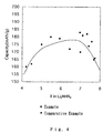
- Example 4 The electrodes were evaluated under the same conditions as in Example 1. The results are shown in Fig. 4, in which the x value of Li x MnN 4 versus the discharge capacity of the electrode in the first charge-discharge cycle were plotted for Examples 1 to 10 and Comparative Examples 1 to 4.
- Fig. 4 indicates that the active materials Li x MnN 4 wherein 5 ⁇ x ⁇ 7.6 are suitable for the electrode.
- the mixture was press-molded into a pellet by applying thereto a pressure of 100kg/cm 2 .
- the pellet was calcinated at 600°C for 10 hours in a nitrogen atmosphere containing 1% hydrogen.
- an active material Li 3 FeN 2 was prepared.
- the active material was analyzed by the powder X-ray diffraction analysis using CuK ⁇ -ray as an X-ray source. The obtained Xray diffraction pattern is shown in Fig. 5.
- test electrode in a pellet form having a diameter of 20mm and a weight of 0.25g was prepared in substantially the same manner as in Example 1, except that the active material thus prepared, acetylene black and polytetrafluoroethylene were mixed in a ratio of 100:20:15.
- the electrode was evaluated by way of a three-electrode method using lithium electrodes as a counter electrode and a reference electrode.
- Used as an electrolytic solution is a solution in which 0.5mol/l lithium trifluoromethane sulfonate was dissolved in a solvent mixture containing ⁇ -butyrolactone and dimethoxyethane in a ratio of 1:1.
- the electrode was charged at a current density of 25.6mA/g up to 1.5V, and then discharged at the same current density to 0.7V.
- the charge-discharge cycle was thereafter repeated in the same potential range and at the same current density.
- the discharge capacity and average potential of the Li 3 FeN 2 electrode were 175mAh/g and 1.2V, respectively, in the first charge-discharge cycle, and 146mAh/g and 1.2V, respectively, in the tenth charge-discharge cycle.
- Lithium nitride (Li 3 N) and metal iron (Fe) powder were mixed in mortars in various Li/Fe ratios. The mixtures were each press-molded into a pellet by applying thereto a pressure of 100kg/cm 2 . The respective pellets were calcinated at 600°C for 10 hours in a nitrogen atmosphere containing 1% hydrogen.
- the compositions of the respective active materials were determined by determining the ratio between lithium and ion by way of the Inductively Coupled Plasma-Atomic Emission Spectroscopy (ICP-AES).
- ICP-AES Inductively Coupled Plasma-Atomic Emission Spectroscopy
- test electrodes in a pellet form having a diameter of 20mm and a weight of 0.25g were prepared in the same manner as in Example 1.
- the electrodes were evaluated under substantially the same conditions as in Example 11, except that a solution in which 1mol/l lithium perchlorate was dissolved in a solvent mixture containing propylene carbonate and ethylmethyl carbonate in a ratio of 1:1.
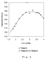
- the results are shown in Fig. 6, in which the x value of Li x FeN 2 versus the discharge capacity of the electrode in the first charge-discharge cycle were plotted for Examples 11 to 18 and Comparative Examples 5 to 9.
- Fig. 6 indicates that the active materials Li x FeN 2 wherein 2.5 ⁇ x ⁇ 3.8 are suitable for the electrode.
- a positive-electrode active material Li 7 MnN 4 and a positive electrode in a pellet form having a diameter of 15mm and a weight of 50mg were prepared in the same manner as in Example 1.
- a pyrolyzed carbon material was employed for a negative electrode.
- a starting material of propane was decomposed at 750°C for two hours under a normal pressure through gas-phase pyrolysis, and the resulting carbon was deposited on a nickel collector (surface area: 4cm 2 ) for the preparation of the electrode.
- the carbon material thus obtained was such that the interfacial distance d 002 between (002) planes was 0.337nm and the crystallite thickness Lc in a (002) plane direction was 15nm.
- the carbon material was such that the ratio (R value) of a peak intensity around 1360cm -1 to that around 1580cm -1 was 0.46.
- a nickel wire was spot-welded to the electrode to establish a current collection line.
- the electrode was dried at 200°C under a reduced pressure to be used as the negative electrode.
- the weight of the active material in the negative electrode was 23mg.
- a battery was fabricated by using a beaker type cell, the positive and negative electrodes thus prepared and an electrolytic solution in which 1 mol/l lithium perchlorate was dissolved in a solvent mixture containing propylene carbonate and diethyl carbonate in a ratio of 1:1.
- the battery thus fabricated was evaluated in the following manner. In a charge-discharge test, the battery was first charged at a current of 0.2mA up to 1.7V and then discharged at the same current to 0.5V in the first charge-discharge cycle. The charge-discharge process was thereafter repeated in the same voltage range and at the same current.
- the discharge capacity and average voltage of the battery were 5.5mAh and 0.9V, respectively, in the first charge-discharge cycle, and 4.8mAh and 0.88V, respectively, in the tenth charge-discharge cycle.
- a positive-electrode active material Li 3 FeN 2 was prepared in the same manner as in Example 11, and a positive electrode in a pellet form having a diameter of 15mm and a thickness of 0.77mm was prepared in the same manner as in Example 1.
- the weight of the active material in the positive electrode was 200mg.
- Natural graphite (produced in Madagascar, flaky shape, particle diameter: 11 ⁇ m, d 002 : 0.337nm, Lc: 27nm, La (the crystallite thickness in an a-axis direction): 17nm, R value: 0, surface area: 8m 2 /g) was employed as a negative-electrode active material.
- the natural graphite and polytetrafluoroethylene were mixed in a ratio of 10:1, and the mixture was press-molded into a pellet having a diameter of 15mm and a thickness of 0.57mm for the preparation of a negative electrode.
- the weight of the active material in the pellet was 90mg.
- a nickel mesh collector was embedded in the pellet.
- the pellet was dried at 200°C under a reduced pressure for removal of moisture therefrom.
- the negative electrode was prepared.
- a coin-type battery as shown in Fig. 7 was fabricated in the following manner.
- the positive electrode 3 including the positive-electrode collector 2 was press-fitted in a positive-electrode case 1 including an insulation packing 8 fitted therein.
- a separator 7 of a polypropylene nonwoven fabric was placed on the positive electrode 3, and impregnated with an electrolytic solution in which lmol/l electrolytic salt LiPF 6 was dissolved in a solvent mixture containing ethylene carbonate, propylene carbonate and diethyl carbonate in a volume ratio of 2:1:3.
- the negative electrode 6 including a negative-electrode collector 5 and fitted in a negativeelectrode case 4 was placed on the separator 7.
- the positive-electrode case 1 was pressedly secured to the negative-electrode case 4 with the insulation packing 8 interposed therebetween for sealing.
- the coin-type battery was fabricated.
- the battery thus fabricated was evaluated by measuring the discharge capacity thereof.
- the battery was charged at a charge current of 1mA up to an upper-limit charge voltage of 1.6V and discharged at a discharge current of 1mA to a lowerlimit voltage of 0.6V in the first charge-discharge cycle.
- the charge-discharge process was thereafter repeated in the same voltage range and at the same current density for the evaluation of the battery.
- the average voltage and discharge capacity of the battery were 0.9V and 22mAh, respectively, in the first charge-discharge cycle, and 0.9V and 19mAh, respectively, in the tenth charge-discharge cycle.
- a negative-electrode active material Li 3 FeN 2 and a negative electrode in a pellet form having a diameter of 15mm and a weight of 50mg were prepared in the same manner as in Example 1.
- a positive-electrode active material V205, acetylene black and polyvinylidene fluoride were mixed in a ratio of 100:10:10, and N-methylpyrrolidone was added to the mixture to obtain a paste.
- the paste was applied on an aluminum foil collector, and dried at 100°C and further at 200°C in vacuum.
- the dried paste was press-molded by applying thereto a pressure of 100Kg/cm 2 to prepare a positive electrode having an area of 4cm 2 and a weight of 70mg.
- An aluminum wire was spot-welded to the electrode to establish a current collection line.
- a battery was fabricated by using a beaker type cell, the positive and negative electrodes thus prepared and an electrolytic solution in which 1 mol/l lithium perchlorate was dissolved in a solvent mixture containing propylene carbonate and diethyl carbonate in a ratio of 2:1.
- the battery thus fabricated was evaluated in the following manner. In a charge-discharge test, the battery was first discharged at a current of 0.2mA to 1.7V and then charged at the same current up to 3.0V in the first discharge-charge cycle. The discharge-charge process was thereafter repeated in the same voltage range and at the same current density.
- the discharge capacity and average voltage of the battery were 5.2mAh and 2.03V, respectively, in the first discharge-charge cycle, and 4.5mAh and 1.98V, respectively, in the tenth discharge-charge cycle.
- a negative-electrode active material Li7MnN4 and a negative electrode in a pellet form having a diameter of 15mm and a thickness of 0.6mm were prepared in the same manner as in Example 1.
- the weight of the active material in the pellet was 0.16g.
- the positive-electrode active material thus prepared, acetylene black and polytetrafluoroethylene were mixed in a mortar in a ratio of 100:10:10, and the mixture was press-molded into a pellet having a diameter of 15mm and a thickness of 0.74mm by applying thereto a pressure of 100Kg/cm 2 .
- the weight of the active material in the pellet was0.20g.
- a titanium mesh collector was embedded in the pellet. The pellet was dried at 200°C under a reduced pressure for removal of moisture therefrom.
- a positive electrode was prepared.
- a coin-type battery was fabricated in the same manner as in Example 20.
- the coin-type battery thus fabricated was first discharged at a current of 1mA to a discharge limit voltage of 0.9V and then charged at the same current up to 3.2V in the first discharge-charge cycle.
- the discharge-charge process was thereafter repeated in the same potential range and at the same current density for the evaluation of the battery.
- the discharge capacity and average potential of the battery were 19mAh and 1.45V, respectively, in the first discharge-charge cycle, 16mAh and 1.41V, respectively, in the tenth discharge-charge cycle, and 14mAh and 1.39V, respectively, in the 100th discharge-charge cycle.
- the battery was excellent in the cycle characteristic and free from the decomposition of the electrolytic solution.
- Positive electrodes were prepared in the same manner as in Example 22.
- Fig. 8 indicates that the active materials LixMnN4 wherein 5 ⁇ x ⁇ 7.6 are suitable for the negative electrode.
- a negative-electrode active material Li 7 MnN 4 and a negative electrode in a pellet form having a diameter of 15mm and a thickness of 0.60mm were prepared in substantially the same manner as in Example 1, except that the active material, acetylene black and polytetrafluoroethylene were mixed in a weight ratio of 100:5:5. The weight of the active material in the pellet was 0.16g.
- the positive-electrode active material thus prepared, acetylene black and polytetrafluoroethylene were mixed in a mortar in a ratio of 100:10:10, and the mixture was press-molded into a pellet having a diameter of 15mm and a thickness of 0.74mm by applying thereto a pressure of 100Kg/cm 2 .
- the weight of the active material in the pellet was 0.20g.
- a titanium mesh collector was embedded in the pellet. The pellet was dried at 100°C under a reduced pressure for removal of moisture therefrom.
- a positive electrode was prepared.
- a coin-type battery was fabricated in substantially the same manner as in Example 20, except that a solution in which lmol/l lithium perchlorate was dissolved in a solvent mixture containing propylene carbonate and ethylmethyl carbonate in a ratio of 1:1 was used as an electrolytic solution.
- the cointype battery thus fabricated was first discharged at a current of 1mA to a discharge limit voltage of 0.9V and then charged at the same current up to 3.2V in the first discharge-charge cycle. The discharge-charge process was thereafter repeated in the same potential range and at the same current density for the evaluation of the battery.
- the discharge capacity and average potential of the battery were 19mAh and 1.48V, respectively, in the first discharge-charge cycle, 17mAh and 1.44V, respectively, in the tenth discharge-charge cycle, and 15mAh and 1.41V, respectively, in the 100th discharge-charge cycle.
- the battery was excellent in the cycle characteristic and free from the decomposition of the electrolytic solution.
- a negative-electrode active material Li 7 MnN 4 and a negative electrode in a pellet form having a diameter of 15mm and a thickness of 0.82mm were prepared in substantially the same manner as in Example 1, except that the active material, acetylene black and polytetrafluoroethylene were mixed in a weight ratio of 100:40:28. The weight of the active material in the pellet was 0.12g.
- the positive-electrode active material thus prepared, acetylene black and polytetrafluoroethylene were mixed in a mortar in a ratio of 100:10:10, and the mixture was press-molded into a pellet having a diameter of 15mm and a thickness of 0.55mm by applying thereto a pressure of 100Kg/cm 2 .
- the weight of the active material in the pellet was 0.15g.
- a titanium mesh collector was embedded in the pellet. The pellet was dried at 100°C under a reduced pressure for removal of moisture therefrom.
- a positive electrode was prepared.
- a coin-type battery was fabricated in substantially the same manner as in Example 20, except that a solution in which lmol/l lithium perchlorate was dissolved in a solvent mixture containing propylene carbonate and ethylmethyl carbonate in a ratio of 1:1 was used as an electrolytic solution.
- the coin-type battery thus fabricated was first discharged at a current of 1mA to a discharge limit voltage of 0.9V and then charged at the same current up to 3.2V in the first discharge-charge cycle. The discharge-charge process was thereafter repeated in the same potential range and at the same current for the evaluation of the battery.
- the discharge capacity and average potential of the battery were 16mAh and 1.55V, respectively, in the first discharge-charge cycle, 14mAh and 1.47V, respectively, in the tenth discharge-charge cycle, and 13mAh and 1.45V, respectively, in the 100th discharge-charge cycle.
- the battery was excellent in the cycle characteristic and free from the decomposition of the electrolytic solution.
- a negative-electrode active material Li7MnN4 and a negative electrode in a pellet form having a diameter of 15mm and a thickness of 0.67mm were prepared in substantially the same manner as in Example 1, except that the active material, acetylene black and polytetrafluoroethylene were mixed in a weight ratio of 100:2:2. The weight of the active material in the pellet was 0.18g.
- a positive-electrode active material of titanium disulfide (TiS 2 ), acetylene black and polytetrafluoroethylene were mixed in a mortar in a ratio of 100:3:4, and the mixture was press-molded into a pellet having a diameter of 15mm and a thickness of 0.67mm by applying thereto a pressure of 100Kg/cm 2 .
- the weight of the active material in the pellet was0.18g.
- a titanium mesh collector was embedded in the pellet. The pellet was dried at 100°C under a reduced pressure for removal of moisture therefrom. Thus, a positive electrode was prepared.
- a coin-type battery was fabricated in substantially the same manner as in Example 20, except that propylene carbonate containing lmol/l lithium perchlorate dissolved therein was used as an electrolytic solution.
- the coin-type battery thus fabricated was first discharged at a current of 1mA to a discharge limit voltage of 0.5V and then charged at the same current up to 3.5V in the first discharge-charge cycle.
- the discharge-charge process was thereafter repeated in the same potential range and at the same current for the evaluation of the battery.
- the discharge capacity and average potential of the battery were 20mAh and 0.82V, respectively, in the first discharge-charge cycle, 18mAh and 0.80V, respectively, in the tenth discharge-charge cycle, and 16mAh and 0.78V, respectively, in the 100th discharge-charge cycle.
- the battery was excellent in the cycle characteristic and free from the decomposition of the electrolytic solution.
- a negative-electrode active material Li 7 MnN 4 and a negative electrode in a pellet form having a diameter of 15mm and a thickness of 0.57mm were prepared in substantially the same manner as in Example 1, except that the active material, acetylene black and polytetrafluoroethylene were mixed in a weight ratio of 100:5:5. The weight of the active material in the pellet was 0.15g.
- a positive-electrode active material of vanadium oxide (V 6 O 13 ), acetylene black and polytetrafluoroethylene were mixed in a mortar in a ratio of 100:35:28, and the mixture was press-molded into a pellet having a diameter of 15mm and a thickness of 0.80mm by applying thereto a pressure of 100Kg/cm 2 .
- the weight of the active material in the pellet was 0.11g.
- a titanium mesh collector was embedded in the pellet. The pellet was dried at 100°C under a reduced pressure for removal of moisture therefrom. Thus, a positive electrode was prepared.
- a coin-type battery was fabricated in the same manner as in Example 20.
- the coin-type battery thus fabricated was first discharged at a current of 1mA to a discharge limit voltage of 0.5V and then charged at the same current up to 3.5V in the first discharge-charge cycle.
- the discharge-charge process was thereafter repeated in the same potential range and at the same current for the evaluation of the battery.
- the discharge capacity and average potential of the battery were 20mAh and 1.02V, respectively, in the first discharge-charge cycle, 18mAh and 0.98V, respectively, in the tenth discharge-charge cycle, and 17mAh and 0.95V, respectively, in the 100th discharge-charge cycle.
- the battery was excellent in the cycle characteristic and free from the decomposition of the electrolytic solution.
- Example 43 an active material Li3FeN2 and a negative electrode in a pellet form having a diameter of 15mm and a thickness of 0.6mm were prepared in the same manner as in Example 11. The weight of the active material in the pellet was 0.16g.
- Positive electrodes were prepared in the same manner as in Example 22.
- Fig. 9 indicates that the negative-electrode active materials Li x MnN 4 wherein 2.5 ⁇ x ⁇ 3.8 are suitable for the negative electrode.
- a negative-electrode active material of natural graphite produced in Madagascar and polytetrafluoroethylene were mixed in a ratio of 10:1, and the mixture was press-molded into a pellet having a diameter of 15mm and a thickness of 0.54mm.
- the weight of the active material in the pellet was 80mg.
- a nickel mesh collector was embedded in the pellet.
- the pellet was dried at 200°C under a reduced pressure for removal of moisture therefrom. Thus, a negative electrode was prepared.
- a positive-electrode active material of LiCoO 2 , acetylene black and polytetrafluoroethylene were mixed in a mortar in a ratio of 100:10:10, and the mixture was press-molded into a pellet having a diameter of 15mm and a thickness of 0.8mm by applying a pressure of 100Kg/cm 2 .
- the weight of the active material in the pellet was 0.22g.
- a titanium mesh collector was embedded in the pellet.
- the pellet was dried at 200°C under a reduced pressure for removal of moisture therefrom.
- a positive electrode was prepared.
- a coin-type battery was fabricated in the same manner as in Example 20.
- the coin-type battery thus fabricated was first charged at a current of 1mA up to a charge limit voltage of 4.5V and then discharged at the same current to 2.7V in the first charge-discharge cycle.
- the charge-discharge process was thereafter repeated in the same potential range and at the same current for the evaluation of the battery.
- the discharge capacity and average potential of the battery were 20mAh and 3.74V, respectively, in the first charge-discharge cycle, 15mAh and 3.68V, respectively, in the tenth charge-discharge cycle, and 9mAh and 3.55V, respectively, in the 100th discharge-charge cycle.
- the deterioration of the cycle characteristic was due to the decomposition of the electrolytic solution.
- a negative-electrode active material Li 7 MnN 4 and a negative electrode in a pellet form having a diameter of 15mm and a thickness of 0.82mm were prepared in the same manner as in Example 22.
- the weight of the active material in the pellet was 0.12g.
- a positive-electrode active material LiCo02 and a positive electrode in a pellet form having a diameter of 15mm and a thickness of 0.74mm were prepared in the same manner as in Comparative Example 19.
- the weight of the active material in the pellet was 0.20g.
- a coin-type battery was prepared in the same manner as in Example 20.
- the coin-type battery was discharged at a current of 1mA to 1.0V. At this time, the discharge capacity of the battery was 1mAh.
- the nonaqueous secondary battery of the present invention includes a positive electrode, a negative electrode and a nonaqueous ion conductor.
- Either one of the positive electrode and the negative electrode contains lithium or a lithium-absorbable and desorbable substance as an active material thereof, and the other electrode contains a lithium transition-metal nitride of an anti-fluorite structure as an active material thereof.
- the battery voltage of the secondary battery can be reduced by employing the lithium transition-metal nitride, for example, as the negative-electrode active material.
- the lithium transition-metal nitride for example, as the negative-electrode active material.
- an active material as manganese dioxide, vanadium pentoxide, titanium sulfide or molybdenum sulfide which is initially in a charged state can be used as the positive-electrode active material.
- the battery voltage can be variously controlled by selecting a positive-electrode active material to be used in combination with the lithium transition-metal nitride.
- the battery voltage of the secondary battery can be variously controlled by employing a carbon or graphite material or a lithium alloy as the negative-electrode active material and the lithium transition-metal nitride as the positive-electrode active material in combination.
- the secondary battery can repeat the charge-discharge process through a lithium-insertion and desertion reaction in the positive- and negative-electrode active materials.
- the secondary battery is substantially free from the decomposition of the electrolytic solution which may otherwise occur due to a lower voltage, and is safe. This makes it possible to variously control the battery voltage, discharge and charge characteristics and cycle characteristics of the secondary battery, thereby increasing the design flexibility of a battery.
- the secondary battery of the present invention can be used in a variety of small-size portable electronic systems.
- the lithium transition-metal nitride represented by Li x MN y (wherein M is Ti, V, Cr, Mn, Fe, Nb, Ta, Mo or W, 1 ⁇ x ⁇ 7.6, and 2 ⁇ y ⁇ 4) enables the secondary battery to supply a lower driving voltage.
- the lithium transition-metal nitride represented by Li x MnN y (5 ⁇ x ⁇ 7.6) or by Li x FeN 2 (2.5 ⁇ y ⁇ 3.8) enables the secondary battery to supply a further lower driving voltage.
- the lithium-absorbable and desorbable active material comprising a carbon or graphite material makes the secondary battery highly safe.
Landscapes
- Chemical & Material Sciences (AREA)
- Engineering & Computer Science (AREA)
- Chemical Kinetics & Catalysis (AREA)
- Electrochemistry (AREA)
- General Chemical & Material Sciences (AREA)
- Materials Engineering (AREA)
- Inorganic Chemistry (AREA)
- Manufacturing & Machinery (AREA)
- Battery Electrode And Active Subsutance (AREA)
- Secondary Cells (AREA)
Abstract
Description
- The present invention relates to a nonaqueous secondary battery. More particularly, the invention relates to a nonaqueous secondary battery comprising a positive electrode, a negative electrode and a nonaqueous ion conductor.
- With the downsizing and energy saving of electronic systems and the like, a voltage required for driving an electronic component such as an IC has been reduced from 5V to 3V and further to below 3V. In addition, the electronic systems have been increasingly provided with a cordless function. For this reason, small-size and light-weight secondary batteries having a high energy density are desired so that such an electronic system can be driven with a voltage applied by a driving source of a single battery.
- Presently available secondary batteries adapted to generate a voltage of higher than 3V include a lithium ion secondary battery (average voltage: 3.6V) utilizing lithium cobaltate as a positive-electrode active material and a carbon material which can be doped and dedoped with lithium ions as a negative-electrode active material. Further, there is proposed a lithium secondary battery utilizing metal lithium or a lithium alloy as a negative electrode thereof and vanadium pentoxide, titanium disulfide, tungsten trioxide or manganese dioxide as a positive-electrode active material.
- However, the lithium ion secondary battery generates a relatively high voltage of 3.6V, though an electronic component such as an IC requires a lower driving voltage. The secondary battery serving as a power source causes a large energy loss. For this reason, it is desirable to reduce the battery voltage of the lithium ion secondary battery.
- In order to reduce the battery voltage, it is necessary to use a positive-electrode active material having a lower potential than lithium cobaltate. Examples of specific positive-electrode active materials include manganese dioxide, vanadium pentoxide, titanium sulfide and molybdenum sulfide. Immediately after a battery is fabricated using such a positive-electrode active material, the positive-electrode active material is in a charged state and, therefore, a discharge process should come first. The lithium ion secondary battery utilizes as a negative-electrode active material a carbon or graphite material or the like which can be doped or dedoped with lithium ions. Immediately after the battery is fabricated using such a negative-electrode active material, the negative-electrode active material is in a discharged state and, therefore, a charge process should come first. Where the aforesaid positive-electrode active material and negative-electrode active material are used in combination for the fabrication of a secondary battery, the resulting secondary battery does not operate.
- To cause the secondary battery using manganese dioxide, vanadium pentoxide, titanium sulfide or molybdenum sulfide as the positive-electrode active material to properly operate, a material initially containing lithium should be used as the negative-electrode active material. Examples of such a lithium-containing substance include metal lithium and lithium alloys.
- However, a lithium secondary battery using metal lithium or a lithium alloy as a negative electrode thereof suffers from the following problems.
- Where lithium metal is used alone as the negative electrode of the battery, dendrite (branching tree-like crystal) is generated on lithium metal during a repeated charge-discharge cycle, i.e., during a lithium dissolution-deposition process. The dendrite grows to penetrate through a separator of the battery and contacts the positive electrode, resulting in a short circuit betweenthe negative and positive elctrode. Further, the generation of the dendrite prevents deposited lithium from being fully used for the charge-discharge process, thereby deteriorating the cycle characteristics of the negative electrode.
- Where a lithium alloy is used instead of lithium metal, the generation of the dendrite is suppressed in comparison with the case where lithium metal is used alone as the negative electrode, and the charge-discharge cycle characteristics are improved. Even with use of the lithium alloy, however, the generation of the dendrite cannot be perfectly prevented, resulting in a short circuit within the secondary battery.
- As described above, it is desirable to reduce the battery voltage of a secondary battery which is to be used in an electronic system requiring a reduced driving voltage. Further, there is a need for a safe secondary battery which employs a positive-electrode active material such as manganese dioxide, vanadium pentoxide, titanium sulfide or molybdenum sulfide which is initially in a charged state, and is free from an internal short circuit.
- As a result of an intensive study, the inventors of the present invention have found that the aforesaid problems can be solved in the following manner, and attained the present invention.
- The present invention provides a nonaqueous secondary battery comprising a positive electrode, a negative electrode and a nonaqueous ion conductor, either one of the positive electrode and the negative electrode containing lithium or a lithium-absorbable and desorbable material as an active material thereof, the other electrode containing a lithium transition-metal nitride of an anti-fluorite type structure as an active material thereof.
-
- Fig. 1 is a schematic diagram illustrating a crystal structure of a lithium transition-metal nitride;
- Fig. 2 is a schematic diagram illustrating a crystal structure of another lithium transition-metal nitride;
- Fig. 3 is an X-ray diffraction pattern of Li7MnN4 used as an electrode active material in Example 1;
- Fig. 4 is a graphical representation illustrating a relationship of initial discharge capacity versus x value of LixMn N4 used as an electrode active material in Examples 1 to 10 and Comparative Examples 1 to 4;
- Fig. 5 is an X-ray diffraction pattern of Li3FeN2 used as an electrode active material in Example 11;
- Fig. 6 is a graphical representation illustrating a relationship of initial discharge capacity versus x value of LixFeN2 used as an electrode active material in Examples 11 to 18 and Comparative Examples 5 to 9;
- Fig. 7 is a schematic sectional view illustrating a cointype battery used in Examples;
- Fig. 8 is a graphical representation illustrating a relationship of initial discharge capacity versus x value of LixMnN4 used as an electrode active material in a coin-type battery in Examples 22 to 31 and Comparative Examples 10 to 13; and
- Fig. 9 is a graphical representation illustrating a relationship of initial discharge capacity versus x value of LixMnN4 used as an electrode active material in a coin-type battery in Examples 36 to 43 and Comparative Examples 14 to 18.
- The lithium transition-metal nitride having the anti-fluorite type structure according to the present invention can be used as an active material of either the positive electrode or the negative electrode. The lithium transition-metal nitride is represented, for example, by a composition formula LixMNy wherein M is a transition metal such as Ti, V, Cr, Mn, Fe, Nb, Ta, Mo or W, 1<x<7.6 and 2<y<4. Where the transition metal is manganese, the lithium transition-metal nitride is represented by LixMnN4 (5<x<7.6) immediately after the preparation thereof, and has a lithium-defect structure, a stoichiometrical structure or a lithium-excess structure. Where the transition metal is iron, the lithium transitionmetal nitride is represented by LixFeN2 (2.5<x<3.8) immediately after the preparation thereof, and has a lithiumdefect structure, a stoichiometrical structure or a lithiumexcess structure. Examples of specific lithium transitionmetal nitrides having a stoichiometrical structure include Li5TiN3, Li7VN4, Li15Cr2N9, Li6CrN4, Li7MnN4, Li3FeN2, Li7NbN4, Li7TaN4, Li6MoN4 and Li6WN4.
- When lithium is inserted into or deserted from the lithium transition-metal nitride during the charge-discharge process, the composition ratio of lithium in the active material changes.
- Fig. 1 is a schematic diagram illustrating an anti-fluorite type crystal structure of Li7VN4, Li7MnN4, Li7NbN4 or Li7TaN4. Fig. 2 is a schematic diagram illustrating an anti-fluorite type crystal structure of Li3FeN2. Li5CrN4, Li15Cr2N9, Li6MoN4 and Li6WN4 have substantially the same crystalline structure as shown in Fig. 1 but have lithium defect. Referring to Figs. 1 and 2, transition metal atoms are located at four coordination positions and lithium atoms are also located at four coordination positions. In Fig. 1, nitrogen atoms are located in a distorted cubic closest-packed arrangement and the transition metal atoms occupy the tetrahedral site forming an anionic three-dimensional network.
Reference numeral 10 denotes lithium atoms. In Fig. 2, nitrogen atoms are located in a distorted cubic closest-packed arrangement and the transition metal atoms occupy the tetrahedral site, in which tetrahedral sharing edges with each other form one-dimensional chains.Reference numeral 12 denotes lithium atoms. - The lithium transition-metal nitride is prepared, for example, in the following manner. Usable as a lithium material is lithium nitride. Usable as a transition metal material is a transition metal or a nitride thereof. The transition metal material is mixed with an excessive amount of lithium nitride. The amount of the lithium nitride depends on the composition of a lithium transition-metal nitride to be prepared. The mixture thus obtained is calcinated at a temperature of 400°C to 1,300°C in a nitrogen atmosphere containing a few-percent hydrogen for the preparation of the lithium transition-metal nitride. Alternatively, the mixture may be first press-molded and then calcinated.
- When the lithium transition-metal nitride thus prepared is used as the active material of an electrode, the electrode is formed of a mixture containing the lithium transition-metal nitride, a conductive material, a binder, an optional solid electrolyte and the like.
- Examples of specific conductive materials include carbon materials such as carbon black, acetylene black and Ketchen black, graphite particles (e.g., natural graphite and artificial graphite), metal powder and metal fiber, but not limited thereto.
- Examples of specific binders include fluoropolymers such as polytetrafluoroethylene and polyvinylidene fluoride, polyolefin polymers such as polyethylene, polypropylene and ethylene-propylene-diene terpolymer, and styrene-butadiene rubber, but not limited thereto.
- The solid electrolyte to be optionally blended is not particularly limited, but may be any of inorganic and organic materials known to be used for an electrode.
- Usable as the inorganic solid electrolyte are a nitride, halides and oxyacid salts of lithium. Examples thereof include Li3N, LiI, Li3N-LiI-LiOH, LiSiO4, LiSiO4-LiI-LiOH, Li3PO4-Li4SiO4, phosphorus sulfide compounds and Li2SiS3.
- Examples of the organic solid electrolytes include polyethylene oxide derivatives, polymers containing polyethylene oxide derivatives, polypropylene oxide derivatives, polymers containing polypropylene oxide derivatives and phosphoric ester polymers.
- The mixing ratio is preferably 1 to 50 parts by weight of the conductive material and 1 to 30 parts by weight of the binder with respect to 100 parts by weight of the active material. If the proportion of the conductive material is less than 1 part by weight, a practical secondary battery cannot be fabricated, because the resistance or polarization of the resulting electrode is increased resulting in a decreased charge and discharge capacity. If the proportion of the conductive material is greater than 50 parts by weight (which may vary depending on the kind of a conductive material to be blended), the charge and discharge capacity of the resulting electrode is undesirably reduced, because the relative content of the active material in the electrode is reduced. If the proportion of the binder is less than 1 part by weight, the binding ability is lost. If the proportion of the binder is greater than 30 parts by weight, the relative content of the active material in the resulting electrode is reduced, like the case of the conductive material. Further, the resistance or polarization of the electrode is increased as described above, so that the charge and discharge capacity thereof is undesirably reduced. This makes the electrode impractical.
- For the preparation of the electrode, the aforesaid mixture is press-molded into a pellet. Alternatively, the aforesaid mixture is mixed with an appropriate solvent, and the resulting paste is applied on a collector, then dried and pressed into a sheet form. The preparation method for the electrode is not limited to these methods.
- As described above, the collector may be used to facilitate the transfer of electrons to/from the electrode. A material for the collector is not particularly limited, but the collector may be formed of a mono-element metal, an alloy, a carbon material or the like. Examples of specific materials for the collector include titanium, iron, nickel, copper, aluminum, stainless steel, and copper, aluminum and stainless steel materials coated with carbon, nickel, titanium, silver or the like, and those materials surface-treated for oxidation. The collector may be in a foil form, a film form, a sheet form, a mesh form, a punched form, a lath form, a porous form or a foamed form, or in a form of fiber compact. The thickness of the collector is not particularly limited, but may be 1µm to 1µm.
- Where the electrode containing the lithium transition-metal nitride as an active material thereof is used as the positive electrode, an electrode containing lithium or a lithium-absorbable and desorbable material is used as the negative electrode. Examples of the lithium-absorbable and desorbable material include lithium alloys such as a lithiumaluminum alloy, a lithium-tin alloy, a lithium-lead alloy and Wood's alloy. However, lithium and lithium alloys may produce dendrite and, therefore, the use of the following active materials is more preferable. Other examples of the lithium-absorbable and desorbable active material include conductive polymers (polyacetylene, polythiophene, polyparaphenylene and the like), pyrolyzed carbon materials, carbon materials pyrolyzed in a gas phase in the presence of a catalyst, carbon materials resulting from calcination of pitch, coke, tar and the like, and carbon materials resulting from the calcination of polymers such as cellulose, phenol and the like. These materials can be electrochemically doped and dedoped with lithium ions. Further other examples thereof include graphite materials (e.g., natural graphite, artificial graphite, expanded graphite and the like) which can intercalate and deintercalate lithium ions, and inorganic compounds (e.g., WO2, MoO2 and the like) which can be doped and dedoped with lithium ions. These active materials may be used alone or in combination.
- Among the aforesaid negative-electrode active materials, the pyrolyzed carbon materials, the carbon materials pyrolyzed in a gas phase in the presence of a catalyst, the carbon materials resulting from the calcination of pitch, coke, tar and the like, the carbon materials resulting from the calcination of polymers and graphite materials (natural graphite, artificial graphite, expanded graphite and the like) are particularly preferred because the resulting secondary battery is excellent in battery characteristics and safety.
- Where the conductive polymers, carbon materials, graphite materials, inorganic compounds and the like are used as the negative-electrode active material, a conductive material and a binder may be added thereto.
- Examples of specific conductive materials include carbon materials such as carbon black, acetylene black and Ketchen black, graphite particles (e.g., natural graphite, artificial graphite and the like), metal powder and metal fiber, but not limited thereto.
- Examples of specific binders include fluoropolymers such as polytetrafluoroethylene and polyvinylidene fluoride, polyolefin polymers such as polyethylene, polypropylene and ethylene-propylene-diene terpolymer, and styrene-butadiene rubber, but not limited thereto.
- Where the electrode containing the lithium transition-metal nitride as an active material thereof is used as the negative electrode, an electrode containing a lithium-absorbable and desorbable active material is used as the positive electrode. Usable as a positive electrode active material are lithium-insertable and desertable chalcogen compounds. Examples thereof include such chalcogen compounds as lithium-containing oxides such as LiCoO2, LiNiO2, LiFeO2, LiMnO2 and LiVO2, manganese oxide, titanium oxide, vanadium oxide, tungsten oxide, molybdenum oxide, niobium oxide, chromium oxide, titanium sulfide, molybdenum sulfide, niobium sulfide, vanadium sulfide, titanium selenide and molybdemun selenide.
- The negative electrode containing the lithium transitionmetal nitride as the active material thereof initially retains lithium and, therefore, the positive electrode is first subjected to a discharge process. The positive-electrode active material is preferably a lithium-insertable active material, i.e., an active material which does not contain lithium initially. Therefore, chalcogen compounds such as manganese oxide, titanium oxide, vanadium oxide, tungsten oxide, molybdenum oxide, niobium oxide, chromium oxide, titanium sulfide, molybdenum sulfide, niobium sulfide, vanadium sulfide, titanium selenide and molybdenum selenide are preferably used as the positive-electrode active material. Further, a lithium-containing manganese compound having a composition ratio Li/Mn of less than 1/2 can serve as a lithium-insertable positive-electrode active material. Among the chalcogen compounds described above, MnO2, V2O5, V6O13, TiO2, WO3, MoO3, Nb2O5, VO2, CrO2, Cr3O8, TiS2, MoS2, MoS3 and lithium-containing manganese oxide are particularly preferred as the positive-electrode active material.
- When any of the aforesaid compounds is used as the positive-electrode active material, the positive electrode is formed of a mixture containing the active material, a conductive material, a binder, an optional solid electrolyte and the like.
- Examples of specific conductive materials include carbon materials such as carbon black, acetylene black and Ketchen black, graphite particles (e.g., natural graphite, artificial graphite and the like), metal powder and metal fiber, but not limited thereto.
- Examples of specific binders include fluoropolymers such as polytetrafluoroethylene and polyvinylidene fluoride, polyolefin polymers such as polyethylene, polypropylene and ethylene-propylene-diene terpolymer, and styrene-butadiene rubber, but not limited thereto.
- The mixing ratio is preferably 1 to 50 parts by weight of the conductive material and 1 to 30 parts by weight of the binder with respect to 100 parts by weight of the active material. If the proportion of the conductive material is less than 1 part by weight, a practical secondary battery cannot be fabricated, because the resistance or polarization of the resulting electrode is increased resulting in a decreased charge and discharge capacity. If the proportion of the conductive material is greater than 50 parts by weight (which may vary depending on the kind of a conductive material to be blended), the charge and discharge capacity of the resulting electrode is undesirably reduced, because the relative content of the active material in the electrode is reduced. If the proportion of the binder is less than 1 part by weight, the binding ability is lost. If the proportion of the binder is greater than 30 parts by weight, the relative content of the active material in the resulting electrode is reduced, like the case of the conductive material. Further, the resistance or polarization of the electrode is increased as described above, so that the charge and discharge capacity thereof is undesirably reduced. This makes the electrode impractical.
- Usable as the ion conductor for the secondary battery are organic electrolytic solutions, solid electrolytes (e.g., polymer solid electrolyte and inorganic solid electrolytes), molten salts and the like. Among these, organic electrolytic solutions are particularly preferred.
- The organic electrolytic solution comprises an organic solvent and an electrolyte.
- The organic solvent is not particularly limited, but may be a non-protic organic solvent. Examples thereof include such esters as propylene carbonate, ethylene carbonate, butylene carbonate, diethyl carbonate, dimethyl carbonate, methyl ethyl carbonate, Y-butyrolactone, methyl formate and methyl acetate, tetrahydrofuran and substituted tetrahydrofurans such as 2-methyltetrahydrofuran, such ethers as dioxolane, diethyl ether, dimethoxyethane, diethoxyethane and methoxyethoxyethane, dimethylsulfoxide, sulfolane, methylsulfolane and acetonitrile. These organic solvents may be used either alone or as a mixture.
- Examples of specific electrolytes include such lithium salts as lithium perchlorate, lithium borofluoride, lithium phosphofluoride, arsenic lithium hexafluoride, lithium trifluoromethane sulfonate, lithium halides and lithium chloroaluminate, but not limited thereto. These electrolytes may be used either alone or as a mixture.
- The organic electrolytic solution can be prepared by dissolving the electrolyte in any of the aforesaid solvents. Known as an inorganic solid electrolyte are a nitride, halides and oxyacid salts of lithium. Examples thereof include Li3N, LiI, Li3N-LiI-LiOH, LiSiO4, LiSiO4-LiI-LiOH, Li3PO4-Li4SiO4, phosphorus sulfide compounds and Li2SiS3.
- Usable as the organic solid electrolyte are a substance comprising any of the aforesaid electrolytes and a polymer permitting the dissociation of the electrolyte, and a substance comprising a polymer having an ionization group. Examples of the polymer permitting the dissociation of the electrolyte include polyethylene oxide derivatives, polymers containing polyethylene oxide derivatives, polypropylene oxide derivatives, polymers containing polypropylene oxide derivatives and phosphoric ester polymers. Also usable are a polymer matrix material containing any of the aforesaid non-protic polar solvents, a mixture of a polymer having an ionization group and a non-protic polar electrolytic solution and an electrolytic solution containing polyacrylonitrile. The inorganic and organic solid electrolytes may be used in combination.
- A separator is used to retain the ion conductor. Exemplary materials of the separator include nonwoven fabrics and woven fabrics of electrically-insulating synthetic resin fibers, glass fibers and natural fibers, microporous materials and compacts of alumina powder and the like. Among these, nonwoven fabrics of synthetic resin fibers such as of polyethylene and polypropylene are particularly preferred in terms of the quality stability of the battery. A separator made of a nonwoven fabric of any of such synthetic resin fibers or a microporous material may be adapted to isolate the positive electrode and the negative electrode from each other when the battery is abnormally heated to cause the separator to be fused. From the viewpoint of safety, the separator of this type is preferably used.
- The thickness of the separator is not particularly limited as long as the separator can retain a required amount of ion conductor and prevent the short-circuit between the positive electrode and the negative electrode, but may be typically about 0.01mm to about 1mm, preferably about 0.02mm to about 0.05mm.
- The present invention can be applied to any secondary battery in a coin shape, a button shape, a sheet form, a cylindrical shape, a square shape or the like.
- A coin- or button-shaped battery can be fabricated in a common manner. More specifically, the positive electrode and the negative electrode each formed into a pellet form are put in a case, and the electrolyte solution is poured in the case, and then a cover is pressedly secured to the case with an insulation packing interposed therebetween.
- A cylindrical or square battery can also be fabricated in a common manner. Specifically, a sheet electrode is put in a case and electrically connected to the case, and the electrolyte solution is poured in the case. Then, the case is sealed with a sealing body with an insulation packing interposed therebetween or with the sealing body insulated from the case by a hermetic sealing. A safety valve including a safety device may be used as the sealing body. Exemplary safety devices include a fuse, a bimetal and a PTC (positive temperature coefficient) device which function as an overcurrent-preventive device. Additionally, to prevent the increase of the inner pressure of the battery case, the sealing body, the hermetic sealing (gasket) or the battery case may be formed with a slit. Further, an external circuit for preventing over-charge or over-discharge of the battery may be provided.
- The pellet or sheet electrode is preferably dried and demoisturized in advance in a common manner. For example, hot air, vacuum, infrared radiation, far-infrared radiation, microwave and dried air may be used alone or in combination for the drying and demoisturization of the electrode. The temperature for the drying is preferably within a range between 50°C and 380°C. A temperature of lower than 50°C is not preferable because the moisture contained in the electrode cannot completely be removed. A temperature of higher than 380°C is not preferable because the binder may be melted to deform the electrode.
- As described above, the nonaqueous secondary battery of the present invention includes a positive electrode, a negative electrode and a nonaqueous ion conductor. Either one of the positive electrode and the negative electrode contains lithium or a lithium-absorbable and desorbable material as an active material thereof, and the other electrode contains a lithium transition-metal nitride of an anti-fluorite type structure as an active material thereof.
- Since the lithium transition-metal nitride is used as the active material, the battery voltage can be reduced. Thus, the secondary battery exhibits a high energy efficiency as a power source for a low-voltage driven system.
- Where the lithium transition-metal nitride is used as a negative-electrode active material, the absorption and desorption of lithium are permitted, and the discharge process comes first. That is, an active material into which lithium can first be inserted (typically, a chalcogen compound which does not initially contain lithium) can be used as a positive-electrode material. Therefore, the secondary battery is free from the generation of dendrite of lithium. Both the positive-electrode material and the negative-electrode material can repeat the charge-discharge process through a reaction of lithium absorption and desorption. Therefore, the secondary battery is substantially free from the decomposition of the electrolytic solution which may otherwise occur due to a lower voltage, and is safe.
- The lithium transition-metal nitride represented by LixMNy (wherein M is Ti, V, Cr, Mn, Fe, Nb, Ta, Mo or W, 1<x<7.6, and 2<y<4) enables the secondary battery to supply a lower driving voltage.
- Further, the lithium transition-metal nitride represented by LixMnNy (5<x<7.6) or by LixFeN2 (2.5<y<3.8) enables the secondary battery to supply a lower driving voltage.
- Where the lithium transition-metal nitride is used for the positive electrode and a lithium-absorbable and desorbable carbon or graphite material is used for the negative electrode, the secondary battery is free from the generation of dendrite of lithium. The positive-electrode active material and the negative-electrode active material exhibit excellent charge-discharge repetition characteristics through a reaction of lithium insertion and desertion. Further, the secondary battery is substantially free from the decomposition of the electrolytic solution which may otherwise occur due to a lower voltage, and is safe.
- The present invention will hereinafter be described in detail by way of examples thereof.
- Lithium nitride (Li3N) and manganese nitride (Mn4N) were weighed in a ratio of Li:Mn=7.1:1 and mixed in a mortar. The mixture was press-molded into a pellet by applying thereto a pressure of 100kg/cm2. The pellet was calcinated at 600°C for 10 hours in a nitrogen atmosphere containing 1% hydrogen. Thus, an active material Li7MnN4 was prepared. The active material was analyzed by the powder X-ray diffraction analysis using CuK α-ray as an X-ray source. The obtained X-ray diffraction pattern is shown in Fig. 3.
- The active material thus prepared, acetylene black and polytetrafluoroethylene were mixed in a mortar in a ratio of 100:10:5. The mixture was press-molded into a pellet having a diameter of 20mm and a weight of 0.25g. At this time, a stainless steel (SUS304) mesh for use as a collector was embedded in the pellet. A stainless steel wire was spot-welded to the stainless steel mesh to establish a current collection line. Thus, a test electrode was prepared for evaluation thereof.
- The electrode was evaluated by way of a three-electrode method using lithium electrodes as a counter electrode and a reference electrode. Used as an electrolytic solution was propylene carbonate containing lmol/l lithium perchlorate. In the first charge-discharge cycle, the electrode was charged at a current density of 16.8mA/g up to 1.6V, and then discharged at the same current density to 0.8V. The charge-discharge cycle was thereafter repeated in the same potential range and at the same current density.
- As a result, the discharge capacity and average potential of the Li7MnN4 electrode were 170mAh/g and 1.10V, respectively, in the first charge-discharge cycle, and 152mAh/g and 1.03V, respectively, in the tenth charge-discharge cycle.
- Lithium nitride (Li3N) and metal manganese (Mn) powder were mixed in mortars in various Li/Mn ratios. The mixtures were each press-molded into a pellet by applying thereto a pressure of 100kg/cm2. The respective pellets were calcinated at 600°C for 10 hours in a nitrogen atmosphere containing 1% hydrogen. Thus, active materials LixMnN4 were prepared (in Examples 2 to 10, x=5.01, 5.48, 5.94, 6.45, 6.97, 7.11, 7.33, 7.42 and 7.57, respectively; and in Comparative Examples 1 to 4, x=4.21, 4.49, 7.68 and 7.74, respectively). The compositions of the respective active materials were determined by determining the ratio between lithium and manganese by way of the Inductively Coupled Plasma-Atomic Emission Spectroscopy (ICP-AES).
- Using the active materials thus prepared, test electrodes in a pellet form having a diameter of 20mm and a weight of 0.25g were prepared in the same manner as in Example 1.
- The electrodes were evaluated under the same conditions as in Example 1. The results are shown in Fig. 4, in which the x value of LixMnN4 versus the discharge capacity of the electrode in the first charge-discharge cycle were plotted for Examples 1 to 10 and Comparative Examples 1 to 4.
- Fig. 4 indicates that the active materials LixMnN4 wherein 5<x<7.6 are suitable for the electrode.
- Lithium nitride (Li3N) and iron nitride (Fe4N) were weighed in a ratio of Li:Fe=3.1:1 and mixed in a mortar. The mixture was press-molded into a pellet by applying thereto a pressure of 100kg/cm2. The pellet was calcinated at 600°C for 10 hours in a nitrogen atmosphere containing 1% hydrogen. Thus, an active material Li3FeN2 was prepared. The active material was analyzed by the powder X-ray diffraction analysis using CuK α-ray as an X-ray source. The obtained Xray diffraction pattern is shown in Fig. 5.
- A test electrode in a pellet form having a diameter of 20mm and a weight of 0.25g was prepared in substantially the same manner as in Example 1, except that the active material thus prepared, acetylene black and polytetrafluoroethylene were mixed in a ratio of 100:20:15.
- The electrode was evaluated by way of a three-electrode method using lithium electrodes as a counter electrode and a reference electrode. Used as an electrolytic solution is a solution in which 0.5mol/l lithium trifluoromethane sulfonate was dissolved in a solvent mixture containing γ-butyrolactone and dimethoxyethane in a ratio of 1:1. In the first chargedischarge cycle, the electrode was charged at a current density of 25.6mA/g up to 1.5V, and then discharged at the same current density to 0.7V. The charge-discharge cycle was thereafter repeated in the same potential range and at the same current density.
- As a result, the discharge capacity and average potential of the Li3FeN2 electrode were 175mAh/g and 1.2V, respectively, in the first charge-discharge cycle, and 146mAh/g and 1.2V, respectively, in the tenth charge-discharge cycle.
- Lithium nitride (Li3N) and metal iron (Fe) powder were mixed in mortars in various Li/Fe ratios. The mixtures were each press-molded into a pellet by applying thereto a pressure of 100kg/cm2. The respective pellets were calcinated at 600°C for 10 hours in a nitrogen atmosphere containing 1% hydrogen. Thus, active materials LixFeN2 were prepared (in Examples 12 to 18, x=2.52, 2.74, 3.22, 3.46, 3.57, 3.67 and 3.78, respectively; and in Comparative Examples 5 to 9, x=1.82, 1.94, 2.03, 2.24 and 3.98, respectively). The compositions of the respective active materials were determined by determining the ratio between lithium and ion by way of the Inductively Coupled Plasma-Atomic Emission Spectroscopy (ICP-AES).
- Using the active materials thus prepared, test electrodes in a pellet form having a diameter of 20mm and a weight of 0.25g were prepared in the same manner as in Example 1.
- The electrodes were evaluated under substantially the same conditions as in Example 11, except that a solution in which 1mol/l lithium perchlorate was dissolved in a solvent mixture containing propylene carbonate and ethylmethyl carbonate in a ratio of 1:1. The results are shown in Fig. 6, in which the x value of LixFeN2 versus the discharge capacity of the electrode in the first charge-discharge cycle were plotted for Examples 11 to 18 and Comparative Examples 5 to 9.
- Fig. 6 indicates that the active materials LixFeN2 wherein 2.5<x<3.8 are suitable for the electrode.
- A positive-electrode active material Li7MnN4 and a positive electrode in a pellet form having a diameter of 15mm and a weight of 50mg were prepared in the same manner as in Example 1.
- A pyrolyzed carbon material was employed for a negative electrode. A starting material of propane was decomposed at 750°C for two hours under a normal pressure through gas-phase pyrolysis, and the resulting carbon was deposited on a nickel collector (surface area: 4cm2) for the preparation of the electrode. According to the X-ray diffraction analysis, the carbon material thus obtained was such that the interfacial distance d002 between (002) planes was 0.337nm and the crystallite thickness Lc in a (002) plane direction was 15nm. According to the argon laser Raman spectroscopy, the carbon material was such that the ratio (R value) of a peak intensity around 1360cm-1 to that around 1580cm-1 was 0.46. A nickel wire was spot-welded to the electrode to establish a current collection line. The electrode was dried at 200°C under a reduced pressure to be used as the negative electrode. The weight of the active material in the negative electrode was 23mg.
- A battery was fabricated by using a beaker type cell, the positive and negative electrodes thus prepared and an electrolytic solution in which 1 mol/l lithium perchlorate was dissolved in a solvent mixture containing propylene carbonate and diethyl carbonate in a ratio of 1:1. The battery thus fabricated was evaluated in the following manner. In a charge-discharge test, the battery was first charged at a current of 0.2mA up to 1.7V and then discharged at the same current to 0.5V in the first charge-discharge cycle. The charge-discharge process was thereafter repeated in the same voltage range and at the same current.
- As a result, the discharge capacity and average voltage of the battery were 5.5mAh and 0.9V, respectively, in the first charge-discharge cycle, and 4.8mAh and 0.88V, respectively, in the tenth charge-discharge cycle.
- A positive-electrode active material Li3FeN2 was prepared in the same manner as in Example 11, and a positive electrode in a pellet form having a diameter of 15mm and a thickness of 0.77mm was prepared in the same manner as in Example 1. The weight of the active material in the positive electrode was 200mg.
- Natural graphite (produced in Madagascar, flaky shape, particle diameter: 11µm, d002: 0.337nm, Lc: 27nm, La (the crystallite thickness in an a-axis direction): 17nm, R value: 0, surface area: 8m2/g) was employed as a negative-electrode active material. The natural graphite and polytetrafluoroethylene were mixed in a ratio of 10:1, and the mixture was press-molded into a pellet having a diameter of 15mm and a thickness of 0.57mm for the preparation of a negative electrode. The weight of the active material in the pellet was 90mg. At the press-molding, a nickel mesh collector was embedded in the pellet. The pellet was dried at 200°C under a reduced pressure for removal of moisture therefrom. Thus, the negative electrode was prepared.
- A coin-type battery as shown in Fig. 7 was fabricated in the following manner. The
positive electrode 3 including the positive-electrode collector 2 was press-fitted in a positive-electrode case 1 including aninsulation packing 8 fitted therein. Aseparator 7 of a polypropylene nonwoven fabric was placed on thepositive electrode 3, and impregnated with an electrolytic solution in which lmol/l electrolytic salt LiPF6 was dissolved in a solvent mixture containing ethylene carbonate, propylene carbonate and diethyl carbonate in a volume ratio of 2:1:3. Thenegative electrode 6 including a negative-electrode collector 5 and fitted in anegativeelectrode case 4 was placed on theseparator 7. In turn, the positive-electrode case 1 was pressedly secured to the negative-electrode case 4 with the insulation packing 8 interposed therebetween for sealing. Thus, the coin-type battery was fabricated. - The battery thus fabricated was evaluated by measuring the discharge capacity thereof. The battery was charged at a charge current of 1mA up to an upper-limit charge voltage of 1.6V and discharged at a discharge current of 1mA to a lowerlimit voltage of 0.6V in the first charge-discharge cycle. The charge-discharge process was thereafter repeated in the same voltage range and at the same current density for the evaluation of the battery.
- As a result, the average voltage and discharge capacity of the battery were 0.9V and 22mAh, respectively, in the first charge-discharge cycle, and 0.9V and 19mAh, respectively, in the tenth charge-discharge cycle.
- A negative-electrode active material Li3FeN2 and a negative electrode in a pellet form having a diameter of 15mm and a weight of 50mg were prepared in the same manner as in Example 1.
- A positive-electrode active material V205, acetylene black and polyvinylidene fluoride were mixed in a ratio of 100:10:10, and N-methylpyrrolidone was added to the mixture to obtain a paste. The paste was applied on an aluminum foil collector, and dried at 100°C and further at 200°C in vacuum. The dried paste was press-molded by applying thereto a pressure of 100Kg/cm2 to prepare a positive electrode having an area of 4cm2 and a weight of 70mg. An aluminum wire was spot-welded to the electrode to establish a current collection line.
- A battery was fabricated by using a beaker type cell, the positive and negative electrodes thus prepared and an electrolytic solution in which 1 mol/l lithium perchlorate was dissolved in a solvent mixture containing propylene carbonate and diethyl carbonate in a ratio of 2:1. The battery thus fabricated was evaluated in the following manner. In a charge-discharge test, the battery was first discharged at a current of 0.2mA to 1.7V and then charged at the same current up to 3.0V in the first discharge-charge cycle. The discharge-charge process was thereafter repeated in the same voltage range and at the same current density.
- As a result, the discharge capacity and average voltage of the battery were 5.2mAh and 2.03V, respectively, in the first discharge-charge cycle, and 4.5mAh and 1.98V, respectively, in the tenth discharge-charge cycle.
- A negative-electrode active material Li7MnN4 and a negative electrode in a pellet form having a diameter of 15mm and a thickness of 0.6mm were prepared in the same manner as in Example 1. The weight of the active material in the pellet was 0.16g.
- Lithium hydroxide and manganese dioxide (I.C.No.12) were mixed in a ratio of Li:Mn=3:10, and the mixture was heattreated at 400°C in air for 48 hours to prepare a positive-electrode active material of lithium-containing manganese dioxide. The positive-electrode active material thus prepared, acetylene black and polytetrafluoroethylene were mixed in a mortar in a ratio of 100:10:10, and the mixture was press-molded into a pellet having a diameter of 15mm and a thickness of 0.74mm by applying thereto a pressure of 100Kg/cm2. The weight of the active material in the pellet was0.20g. At the press-molding, a titanium mesh collector was embedded in the pellet. The pellet was dried at 200°C under a reduced pressure for removal of moisture therefrom. Thus, a positive electrode was prepared.
- A coin-type battery was fabricated in the same manner as in Example 20.
- The coin-type battery thus fabricated was first discharged at a current of 1mA to a discharge limit voltage of 0.9V and then charged at the same current up to 3.2V in the first discharge-charge cycle. The discharge-charge process was thereafter repeated in the same potential range and at the same current density for the evaluation of the battery.
- As a result, the discharge capacity and average potential of the battery were 19mAh and 1.45V, respectively, in the first discharge-charge cycle, 16mAh and 1.41V, respectively, in the tenth discharge-charge cycle, and 14mAh and 1.39V, respectively, in the 100th discharge-charge cycle. As can be understood from the foregoing, the battery was excellent in the cycle characteristic and free from the decomposition of the electrolytic solution.
- Negative-electrode active materials LixMnN4 (in Examples 23 to 31, x=5.01, 5.48, 5.94, 6.45, 6.97, 7.11, 7.33, 7.42 and 7.57, respectively; and in Comparative Examples 10 to 13, x=4.21, 4.49, 7.68 and 7.74, respectively) and negative electrodes in a pellet form having a diameter of 15mm and a thickness of 0.6mm were prepared in the same manner as in Examples 2 to 10 and Comparative Examples 1 to 4, respectively. The weight of the active material in each pellet was 0.16g.
- Positive electrodes were prepared in the same manner as in Example 22.
- Coin-type batteries were fabricated and evaluated in the same manner as in Example 22.
- The results are shown in Fig. 8, in which the x value of LixMnN4 versus the discharge capacity of the electrode in the first discharge-charge cycle were plotted for Examples 22 to 31 and Comparative Examples 10 to 13.
- Fig. 8 indicates that the active materials LixMnN4 wherein 5<x<7.6 are suitable for the negative electrode.
- A negative-electrode active material Li7MnN4 and a negative electrode in a pellet form having a diameter of 15mm and a thickness of 0.60mm were prepared in substantially the same manner as in Example 1, except that the active material, acetylene black and polytetrafluoroethylene were mixed in a weight ratio of 100:5:5. The weight of the active material in the pellet was 0.16g.
- Lithium hydroxide and manganese dioxide (I.C.No.12) were mixed in a ratio of Li:Mn=1:10, and the mixture was heattreated at 450°C in air for 48 hours to prepare a positive-electrode active material of lithium-containing manganese dioxide. The positive-electrode active material thus prepared, acetylene black and polytetrafluoroethylene were mixed in a mortar in a ratio of 100:10:10, and the mixture was press-molded into a pellet having a diameter of 15mm and a thickness of 0.74mm by applying thereto a pressure of 100Kg/cm2. The weight of the active material in the pellet was 0.20g. At the press-molding, a titanium mesh collector was embedded in the pellet. The pellet was dried at 100°C under a reduced pressure for removal of moisture therefrom. Thus, a positive electrode was prepared.
- A coin-type battery was fabricated in substantially the same manner as in Example 20, except that a solution in which lmol/l lithium perchlorate was dissolved in a solvent mixture containing propylene carbonate and ethylmethyl carbonate in a ratio of 1:1 was used as an electrolytic solution. The cointype battery thus fabricated was first discharged at a current of 1mA to a discharge limit voltage of 0.9V and then charged at the same current up to 3.2V in the first discharge-charge cycle. The discharge-charge process was thereafter repeated in the same potential range and at the same current density for the evaluation of the battery.
- As a result, the discharge capacity and average potential of the battery were 19mAh and 1.48V, respectively, in the first discharge-charge cycle, 17mAh and 1.44V, respectively, in the tenth discharge-charge cycle, and 15mAh and 1.41V, respectively, in the 100th discharge-charge cycle. As can be understood from the foregoing, the battery was excellent in the cycle characteristic and free from the decomposition of the electrolytic solution.
- A negative-electrode active material Li7MnN4 and a negative electrode in a pellet form having a diameter of 15mm and a thickness of 0.82mm were prepared in substantially the same manner as in Example 1, except that the active material, acetylene black and polytetrafluoroethylene were mixed in a weight ratio of 100:40:28. The weight of the active material in the pellet was 0.12g.
- Lithium hydroxide and manganese dioxide (I.C.No.12) were mixed in a ratio of Li:Mn=1.1:2, and the mixture was heattreated at 700°C in air for 20 hours to prepare a positiveelectrode active material of lithium-containing manganese dioxide (spinel-type lithium manganese oxide LiMn2O4). The positive-electrode active material thus prepared, acetylene black and polytetrafluoroethylene were mixed in a mortar in a ratio of 100:10:10, and the mixture was press-molded into a pellet having a diameter of 15mm and a thickness of 0.55mm by applying thereto a pressure of 100Kg/cm2. The weight of the active material in the pellet was 0.15g. At the pressmolding, a titanium mesh collector was embedded in the pellet. The pellet was dried at 100°C under a reduced pressure for removal of moisture therefrom. Thus, a positive electrode was prepared.
- A coin-type battery was fabricated in substantially the same manner as in Example 20, except that a solution in which lmol/l lithium perchlorate was dissolved in a solvent mixture containing propylene carbonate and ethylmethyl carbonate in a ratio of 1:1 was used as an electrolytic solution. The coin-type battery thus fabricated was first discharged at a current of 1mA to a discharge limit voltage of 0.9V and then charged at the same current up to 3.2V in the first discharge-charge cycle. The discharge-charge process was thereafter repeated in the same potential range and at the same current for the evaluation of the battery.
- As a result, the discharge capacity and average potential of the battery were 16mAh and 1.55V, respectively, in the first discharge-charge cycle, 14mAh and 1.47V, respectively, in the tenth discharge-charge cycle, and 13mAh and 1.45V, respectively, in the 100th discharge-charge cycle. As can be understood from the foregoing, the battery was excellent in the cycle characteristic and free from the decomposition of the electrolytic solution.
- A negative-electrode active material Li7MnN4 and a negative electrode in a pellet form having a diameter of 15mm and a thickness of 0.67mm were prepared in substantially the same manner as in Example 1, except that the active material, acetylene black and polytetrafluoroethylene were mixed in a weight ratio of 100:2:2. The weight of the active material in the pellet was 0.18g.
- A positive-electrode active material of titanium disulfide (TiS2), acetylene black and polytetrafluoroethylene were mixed in a mortar in a ratio of 100:3:4, and the mixture was press-molded into a pellet having a diameter of 15mm and a thickness of 0.67mm by applying thereto a pressure of 100Kg/cm2. The weight of the active material in the pellet was0.18g. At the press-molding, a titanium mesh collector was embedded in the pellet. The pellet was dried at 100°C under a reduced pressure for removal of moisture therefrom. Thus, a positive electrode was prepared.
- A coin-type battery was fabricated in substantially the same manner as in Example 20, except that propylene carbonate containing lmol/l lithium perchlorate dissolved therein was used as an electrolytic solution.
- The coin-type battery thus fabricated was first discharged at a current of 1mA to a discharge limit voltage of 0.5V and then charged at the same current up to 3.5V in the first discharge-charge cycle. The discharge-charge process was thereafter repeated in the same potential range and at the same current for the evaluation of the battery.
- As a result, the discharge capacity and average potential of the battery were 20mAh and 0.82V, respectively, in the first discharge-charge cycle, 18mAh and 0.80V, respectively, in the tenth discharge-charge cycle, and 16mAh and 0.78V, respectively, in the 100th discharge-charge cycle. As can be understood from the foregoing, the battery was excellent in the cycle characteristic and free from the decomposition of the electrolytic solution.
- A negative-electrode active material Li7MnN4 and a negative electrode in a pellet form having a diameter of 15mm and a thickness of 0.57mm were prepared in substantially the same manner as in Example 1, except that the active material, acetylene black and polytetrafluoroethylene were mixed in a weight ratio of 100:5:5. The weight of the active material in the pellet was 0.15g.
- A positive-electrode active material of vanadium oxide (V6O13), acetylene black and polytetrafluoroethylene were mixed in a mortar in a ratio of 100:35:28, and the mixture was press-molded into a pellet having a diameter of 15mm and a thickness of 0.80mm by applying thereto a pressure of 100Kg/cm2. The weight of the active material in the pellet was 0.11g. At the press-molding, a titanium mesh collector was embedded in the pellet. The pellet was dried at 100°C under a reduced pressure for removal of moisture therefrom. Thus, a positive electrode was prepared.
- A coin-type battery was fabricated in the same manner as in Example 20.
- The coin-type battery thus fabricated was first discharged at a current of 1mA to a discharge limit voltage of 0.5V and then charged at the same current up to 3.5V in the first discharge-charge cycle. The discharge-charge process was thereafter repeated in the same potential range and at the same current for the evaluation of the battery.
- As a result, the discharge capacity and average potential of the battery were 20mAh and 1.02V, respectively, in the first discharge-charge cycle, 18mAh and 0.98V, respectively, in the tenth discharge-charge cycle, and 17mAh and 0.95V, respectively, in the 100th discharge-charge cycle. As can be understood from the foregoing, the battery was excellent in the cycle characteristic and free from the decomposition of the electrolytic solution.
- Negative-electrode active materials LixFeN2 (in Examples 36 to 42, x=2.52, 2.74, 3.22, 3.46, 3.57, 3.67 and 3.78, respectively; and in Comparative Examples 14 to 18, x=1.82, 1.94, 2.03, 2.24 and 3.98, respectively) and negative electrodes in a pellet form having a diameter of 15mm and a thickness of 0.6mm were prepared in the same manner as in Examples 12 to 18 and Comparative Examples 5 to 9, respectively. The weight of the active material in each pellet was 0.16g. In Example 43, an active material Li3FeN2 and a negative electrode in a pellet form having a diameter of 15mm and a thickness of 0.6mm were prepared in the same manner as in Example 11. The weight of the active material in the pellet was 0.16g.
- Positive electrodes were prepared in the same manner as in Example 22.
- Coin-type batteries were fabricated and evaluated in the same manner as in Example 22.
- The results are shown in Fig. 9, in which the x value of LixMnN4 versus the discharge capacity of the electrode in the first discharge-charge cycle were plotted for Examples 36 to 43 and Comparative Examples 14 to 18.
- Fig. 9 indicates that the negative-electrode active materials LixMnN4 wherein 2.5<x<3.8 are suitable for the negative electrode.
- A negative-electrode active material of natural graphite produced in Madagascar and polytetrafluoroethylene were mixed in a ratio of 10:1, and the mixture was press-molded into a pellet having a diameter of 15mm and a thickness of 0.54mm. The weight of the active material in the pellet was 80mg. At the press-molding, a nickel mesh collector was embedded in the pellet. The pellet was dried at 200°C under a reduced pressure for removal of moisture therefrom. Thus, a negative electrode was prepared.
- A positive-electrode active material of LiCoO2, acetylene black and polytetrafluoroethylene were mixed in a mortar in a ratio of 100:10:10, and the mixture was press-molded into a pellet having a diameter of 15mm and a thickness of 0.8mm by applying a pressure of 100Kg/cm2. The weight of the active material in the pellet was 0.22g. At the press-molding, a titanium mesh collector was embedded in the pellet. The pellet was dried at 200°C under a reduced pressure for removal of moisture therefrom. Thus, a positive electrode was prepared.
- A coin-type battery was fabricated in the same manner as in Example 20.
- The coin-type battery thus fabricated was first charged at a current of 1mA up to a charge limit voltage of 4.5V and then discharged at the same current to 2.7V in the first charge-discharge cycle. The charge-discharge process was thereafter repeated in the same potential range and at the same current for the evaluation of the battery.
- As a result, the discharge capacity and average potential of the battery were 20mAh and 3.74V, respectively, in the first charge-discharge cycle, 15mAh and 3.68V, respectively, in the tenth charge-discharge cycle, and 9mAh and 3.55V, respectively, in the 100th discharge-charge cycle. The deterioration of the cycle characteristic was due to the decomposition of the electrolytic solution.
- A negative-electrode active material Li7MnN4 and a negative electrode in a pellet form having a diameter of 15mm and a thickness of 0.82mm were prepared in the same manner as in Example 22. The weight of the active material in the pellet was 0.12g.
- A positive-electrode active material LiCo02 and a positive electrode in a pellet form having a diameter of 15mm and a thickness of 0.74mm were prepared in the same manner as in Comparative Example 19. The weight of the active material in the pellet was 0.20g.
- A coin-type battery was prepared in the same manner as in Example 20.
- The coin-type battery was discharged at a current of 1mA to 1.0V. At this time, the discharge capacity of the battery was 1mAh.
- As described above, the nonaqueous secondary battery of the present invention includes a positive electrode, a negative electrode and a nonaqueous ion conductor. Either one of the positive electrode and the negative electrode contains lithium or a lithium-absorbable and desorbable substance as an active material thereof, and the other electrode contains a lithium transition-metal nitride of an anti-fluorite structure as an active material thereof.
- The battery voltage of the secondary battery can be reduced by employing the lithium transition-metal nitride, for example, as the negative-electrode active material. Further, such an active material as manganese dioxide, vanadium pentoxide, titanium sulfide or molybdenum sulfide which is initially in a charged state can be used as the positive-electrode active material. Thus, the battery voltage can be variously controlled by selecting a positive-electrode active material to be used in combination with the lithium transition-metal nitride.
- Further, the battery voltage of the secondary battery can be variously controlled by employing a carbon or graphite material or a lithium alloy as the negative-electrode active material and the lithium transition-metal nitride as the positive-electrode active material in combination.
- The secondary battery can repeat the charge-discharge process through a lithium-insertion and desertion reaction in the positive- and negative-electrode active materials. In addition, the secondary battery is substantially free from the decomposition of the electrolytic solution which may otherwise occur due to a lower voltage, and is safe. This makes it possible to variously control the battery voltage, discharge and charge characteristics and cycle characteristics of the secondary battery, thereby increasing the design flexibility of a battery. Thus, the secondary battery of the present invention can be used in a variety of small-size portable electronic systems.
- The lithium transition-metal nitride represented by LixMNy (wherein M is Ti, V, Cr, Mn, Fe, Nb, Ta, Mo or W, 1<x<7.6, and 2<y<4) enables the secondary battery to supply a lower driving voltage.
- The lithium transition-metal nitride represented by LixMnNy (5<x<7.6) or by LixFeN2 (2.5<y<3.8) enables the secondary battery to supply a further lower driving voltage.
- The lithium-absorbable and desorbable active material comprising a carbon or graphite material makes the secondary battery highly safe.
Claims (13)
- A nonaqueous secondary battery comprising a positive electrode, a negative electrode and a nonaqueous ion conductor, either one of the positive electrode and the negative electrode containing lithium or a lithium-absorbable and desorbable substance as an active material thereof, the other electrode containing a lithium transition-metal nitride of an anti-fluorite type structure as an active material thereof.
- A nonaqueous secondary battery as set forth in claim 1, wherein the lithium transition-metal nitride of the anti-fluorite type structure is represented by LixMNy wherein M is Ti, V, Cr, Mn, Fe, Nb, Ta, Mo or W, 1<x<7.6 and 2<y<4.
- A nonaqueous secondary battery as set forth in claim 2, wherein the lithium transition-metal nitride of the anti-fluorite type structre is represented by LixHnN4 wherein 5<x<7.6 or by LixFeN2 wherein 2.5<x<3.8.
- A nonaqueous secondary battery as set forth in claim 1, wherein the lithium-absorbable and desorbable substance is a carbon material, a graphite material, a chalcogen compound, a transition-metal or a lithium-containing manganese dioxide having a compositions ratio Li/Mn of not greater than 1/2.
- A nonaqueous secondary battery as set forth in claim 4, wherein the negative electrode contains the carbon or graphite material as the active material, the positive electrode contains the lithium transition-metal nitride of the anti-fluorite type structure as the active material.
- A nonaqueous secondary battery as set forth in claim 4, wherein the negative electrode contains the lithium transition-metal nitride of the anti-fluorite type structure as the active material, the positive electrode contains the chalcogen compound as the active material.
- A nonaqueous secondary battery as set forth in claim 4, wherein the negative electrode contains the lithium transition-metal nitride of the anti-fluorite type structure as the active material, the positive electrode contains the transition-metal oxide as the active material.
- A nonaqueous secondary battery as set forth in claim 7, wherein the transition-metal oxide includes at least one of MnO2, V2O5, V6O13, TiO2, WO3, MoO3, Nb2O5, VO2, CrO2, Cr3O8, TiS2, MoS2 and MoS3.
- A nonaqueous secondary battery as set forth in claim 4, wherein the negative electrode contains the lithium transition-metal nitride of an anti-fluorite type structure as the active material, the positive electrode contains the lithium-containing manganese dioxide having a composition ratio Li/Mn of not greater than 1/2.
- A nonaqueous secondary battery comprising a positive electrode, a negative electrode and a nonaqueous ion conductor, the negative electrode containing a lithium transition-metal nitride of an anti-fluorite type structure as an active material thereof, the positive electrode containing as an active material thereof a lithium-containing manganese dioxide having a composition ratio Li/Mn of not greater than 1/2.
- A nonaqueous secondary battery as set forth in claim 10, wherein the lithium transition-metal nitride is represented by LixMNy wherein M is Ti, V, Cr, Mn, Fe, Nb, Ta, Mo or W, 1<x<7.6 and 2<y<4.
- A nonaqueous secondary battery as set forth in claim 11, wherein the lithium transition-metal nitride is represented by LixMnN4 wherein 5<x<7.6 or by LixFeN2 wherein 2.5<x<3.8.
- Non-aqueous secondary cell in which the positive or negative electrode contains a lithium transition-metal nitride as an active material.
Applications Claiming Priority (6)
| Application Number | Priority Date | Filing Date | Title |
|---|---|---|---|
| JP125176/95 | 1995-05-24 | ||
| JP12517695 | 1995-05-24 | ||
| JP12517695 | 1995-05-24 | ||
| JP8664996 | 1996-04-09 | ||
| JP86649/96 | 1996-04-09 | ||
| JP8086649A JPH0945330A (en) | 1995-05-24 | 1996-04-09 | Non-aqueous secondary battery |
Publications (2)
| Publication Number | Publication Date |
|---|---|
| EP0744782A1 true EP0744782A1 (en) | 1996-11-27 |
| EP0744782B1 EP0744782B1 (en) | 2003-03-26 |
Family
ID=26427755
Family Applications (1)
| Application Number | Title | Priority Date | Filing Date |
|---|---|---|---|
| EP96303119A Expired - Lifetime EP0744782B1 (en) | 1995-05-24 | 1996-05-02 | Nonaqueous secondary battery |
Country Status (3)
| Country | Link |
|---|---|
| US (1) | US5702843A (en) |
| EP (1) | EP0744782B1 (en) |
| DE (1) | DE69626883T2 (en) |
Cited By (6)
| Publication number | Priority date | Publication date | Assignee | Title |
|---|---|---|---|---|
| EP1014460A1 (en) * | 1998-12-21 | 2000-06-28 | Wilson Greatbatch Ltd. | Annealing of mixed metal oxide electrodes to reduce polarization resistance |
| EP1034572A4 (en) * | 1997-10-30 | 2004-08-18 | T J Technologies Inc | CERAMIC MATERIAL BASED ON TRANSITIONAL METAL AND ARTICLES PRODUCED THEREWITH |
| FR2864708A1 (en) * | 2003-12-26 | 2005-07-01 | Shin Kobe Electric Machinery | SECONDARY LITHIUM ION BATTERY |
| US6989218B2 (en) | 2000-09-28 | 2006-01-24 | Hitachi Maxell, Ltd. | Composite electrode material and method for producing the same, and electrochemical element using the same |
| US7959360B2 (en) | 2007-02-22 | 2011-06-14 | Staubli Faverges | Antifriction bearing for a weaving loom with lubricating cavity and weaving loom pulling system comprising such a bearing |
| EP3760580A1 (en) * | 2019-07-02 | 2021-01-06 | Hamilton Sundstrand Corporation | Method of making high capacity electrode material |
Families Citing this family (15)
| Publication number | Priority date | Publication date | Assignee | Title |
|---|---|---|---|---|
| US5888669A (en) * | 1996-03-14 | 1999-03-30 | T/J/ Technologies | Transition metal-based ceramic material and articles fabrication therefrom |
| US6190802B1 (en) * | 1998-05-22 | 2001-02-20 | T/J Technologies, Inc. | Transition metal based ceramic material and electrodes fabricated therefrom |
| JP4411691B2 (en) * | 1999-06-30 | 2010-02-10 | パナソニック株式会社 | Non-aqueous electrolyte secondary battery, non-aqueous electrolyte secondary battery charge control system, and equipment using the same |
| AU7557200A (en) * | 1999-10-08 | 2001-04-23 | Seimi Chemical Co., Ltd. | Lithium-cobalt composite oxide, method for preparing the same, positive electrode for lithium secondary cell and lithium secondary cell using the same |
| CA2427111A1 (en) * | 2003-04-30 | 2004-10-30 | Christophe Michot | Polymeric binder for fused salts electrolytes based batteries |
| KR101903939B1 (en) | 2016-01-22 | 2018-10-02 | 아사히 가세이 가부시키가이샤 | Positive electrode precursor |
| TWI629819B (en) * | 2016-01-22 | 2018-07-11 | 旭化成股份有限公司 | Non-aqueous lithium storage element |
| WO2017126691A1 (en) | 2016-01-22 | 2017-07-27 | 旭化成株式会社 | Nonaqueous lithium-type power storage element |
| KR101968886B1 (en) | 2016-01-22 | 2019-04-12 | 아사히 가세이 가부시키가이샤 | Non-aqueous lithium-ion battery device |
| KR101935214B1 (en) | 2016-01-22 | 2019-01-03 | 아사히 가세이 가부시키가이샤 | Non-aqueous lithium-ion battery device |
| JP6262402B2 (en) | 2016-01-22 | 2018-01-17 | 旭化成株式会社 | Non-aqueous lithium storage element |
| TWI628680B (en) | 2016-01-22 | 2018-07-01 | 旭化成股份有限公司 | Non-aqueous lithium storage battery |
| EP3392896B1 (en) | 2016-01-22 | 2020-01-08 | Asahi Kasei Kabushiki Kaisha | Nonaqueous lithium power storage element |
| US11581572B2 (en) | 2018-10-09 | 2023-02-14 | University Of Maryland, College Park | Lithium metal nitrides as lithium super-ionic conductors |
| FR3131452B1 (en) | 2021-12-23 | 2024-03-08 | Renault Sas | Process for delithiation of at least one nitride of transition metal(s) and lithium |
Citations (3)
| Publication number | Priority date | Publication date | Assignee | Title |
|---|---|---|---|---|
| EP0646977A2 (en) * | 1993-09-09 | 1995-04-05 | Matsushita Electric Industrial Co., Ltd. | Electrochemical devices comprising lithium nitride-metal compounds in at least one of a pair of electrodes |
| JPH07320720A (en) * | 1994-05-24 | 1995-12-08 | Matsushita Electric Ind Co Ltd | Electrochemical element |
| JPH0878018A (en) * | 1994-08-31 | 1996-03-22 | Sanyo Electric Co Ltd | Lithium secondary battery |
Family Cites Families (2)
| Publication number | Priority date | Publication date | Assignee | Title |
|---|---|---|---|---|
| US5135732A (en) * | 1991-04-23 | 1992-08-04 | Bell Communications Research, Inc. | Method for preparation of LiMn2 O4 intercalation compounds and use thereof in secondary lithium batteries |
| US5496664A (en) * | 1993-08-18 | 1996-03-05 | Varta Batterie Aktiengesellschaft | Process for producing a positive electrode for lithium secondary batteries |
-
1996
- 1996-04-30 US US08/640,137 patent/US5702843A/en not_active Expired - Fee Related
- 1996-05-02 DE DE69626883T patent/DE69626883T2/en not_active Expired - Fee Related
- 1996-05-02 EP EP96303119A patent/EP0744782B1/en not_active Expired - Lifetime
Patent Citations (3)
| Publication number | Priority date | Publication date | Assignee | Title |
|---|---|---|---|---|
| EP0646977A2 (en) * | 1993-09-09 | 1995-04-05 | Matsushita Electric Industrial Co., Ltd. | Electrochemical devices comprising lithium nitride-metal compounds in at least one of a pair of electrodes |
| JPH07320720A (en) * | 1994-05-24 | 1995-12-08 | Matsushita Electric Ind Co Ltd | Electrochemical element |
| JPH0878018A (en) * | 1994-08-31 | 1996-03-22 | Sanyo Electric Co Ltd | Lithium secondary battery |
Non-Patent Citations (4)
| Title |
|---|
| CHEMICAL ABSTRACTS, vol. 122, no. 6, 6 February 1995, Columbus, Ohio, US; abstract no. 60090, NISHIJIMA: "Li deintercalation and structural change in the lithium transition metal nitride Li3FeN2" XP002012381 * |
| CHEMICAL ABSTRACTS, vol. 124, no. 16, 15 April 1996, Columbus, Ohio, US; abstract no. 207215, TAKADA KAZUNORI ET AL: "Electrochemical devices with improved electrodes" XP002012382 * |
| J. SOLID STATE CHEMISTRY, vol. 113, no. 1, 1994, pages 205 - 210 * |
| PATENT ABSTRACTS OF JAPAN vol. 0, (E - 000) * |
Cited By (8)
| Publication number | Priority date | Publication date | Assignee | Title |
|---|---|---|---|---|
| EP1034572A4 (en) * | 1997-10-30 | 2004-08-18 | T J Technologies Inc | CERAMIC MATERIAL BASED ON TRANSITIONAL METAL AND ARTICLES PRODUCED THEREWITH |
| EP1014460A1 (en) * | 1998-12-21 | 2000-06-28 | Wilson Greatbatch Ltd. | Annealing of mixed metal oxide electrodes to reduce polarization resistance |
| US6989218B2 (en) | 2000-09-28 | 2006-01-24 | Hitachi Maxell, Ltd. | Composite electrode material and method for producing the same, and electrochemical element using the same |
| FR2864708A1 (en) * | 2003-12-26 | 2005-07-01 | Shin Kobe Electric Machinery | SECONDARY LITHIUM ION BATTERY |
| US7959360B2 (en) | 2007-02-22 | 2011-06-14 | Staubli Faverges | Antifriction bearing for a weaving loom with lubricating cavity and weaving loom pulling system comprising such a bearing |
| EP3760580A1 (en) * | 2019-07-02 | 2021-01-06 | Hamilton Sundstrand Corporation | Method of making high capacity electrode material |
| US11094923B2 (en) | 2019-07-02 | 2021-08-17 | Hamilton Sundstrand Corporation | Method of making high capacity electrode material |
| US11682756B2 (en) | 2019-07-02 | 2023-06-20 | Hamilton Sundstrand Corporation | Method of making high capacity electrode material |
Also Published As
| Publication number | Publication date |
|---|---|
| US5702843A (en) | 1997-12-30 |
| DE69626883T2 (en) | 2003-12-04 |
| DE69626883D1 (en) | 2003-04-30 |
| EP0744782B1 (en) | 2003-03-26 |
Similar Documents
| Publication | Publication Date | Title |
|---|---|---|
| EP0744782B1 (en) | Nonaqueous secondary battery | |
| KR100782868B1 (en) | Charging method for charging nonaqueous electrolyte secondary battery | |
| EP0567149B1 (en) | Nonaqueous secondary battery | |
| EP0870339B1 (en) | Electrode material for electrochemical lithium intercalation | |
| EP0782206B1 (en) | Positive electrode active material for lithium secondary battery, method of producing thereof, and lithium secondary battery | |
| US6156457A (en) | Lithium secondary battery and method for manufacturing a negative electrode | |
| JP3813001B2 (en) | Non-aqueous secondary battery | |
| EP0688057B1 (en) | Lithium ion secondary battery | |
| CA2055305C (en) | Nonaqueous electrolyte secondary battery | |
| US5773168A (en) | Nonaqueous electrolyte secondary battery and method for manufacturing the same | |
| JP3436600B2 (en) | Rechargeable battery | |
| KR100325868B1 (en) | Organic electrolytic solution and lithium secondary battery adopting the same | |
| EP0924789B1 (en) | Nonaqueous battery | |
| US9184441B2 (en) | Battery electrode, nonaqueous electrolyte battery, and battery pack | |
| KR20020062692A (en) | Lithium Ion Secondary Cell | |
| EP0798797A1 (en) | Process for preparing positive electrode active materials, and nonaqueous secondary battery utilizing the same | |
| JPH09298061A (en) | Non-aqueous secondary battery | |
| JP3212639B2 (en) | Non-aqueous solvent secondary battery | |
| EP2573844B1 (en) | Nonaqueous electrolyte battery, electrode for the same, and battery pack | |
| KR20000071371A (en) | Non-Aqueous Electrolyte Battery | |
| JP4103168B2 (en) | Non-aqueous secondary battery and manufacturing method thereof | |
| JP2001283861A (en) | Battery electrode and non-aqueous electrolyte battery | |
| KR100396491B1 (en) | Lithium secondary battery | |
| JP3833331B2 (en) | Non-aqueous secondary battery | |
| KR100624970B1 (en) | Cathode active material for lithium secondary battery, manufacturing method thereof, and lithium secondary battery |
Legal Events
| Date | Code | Title | Description |
|---|---|---|---|
| PUAI | Public reference made under article 153(3) epc to a published international application that has entered the european phase |
Free format text: ORIGINAL CODE: 0009012 |
|
| AK | Designated contracting states |
Kind code of ref document: A1 Designated state(s): DE FR GB |
|
| 17P | Request for examination filed |
Effective date: 19970515 |
|
| 17Q | First examination report despatched |
Effective date: 19980512 |
|
| GRAG | Despatch of communication of intention to grant |
Free format text: ORIGINAL CODE: EPIDOS AGRA |
|
| GRAG | Despatch of communication of intention to grant |
Free format text: ORIGINAL CODE: EPIDOS AGRA |
|
| GRAH | Despatch of communication of intention to grant a patent |
Free format text: ORIGINAL CODE: EPIDOS IGRA |
|
| GRAH | Despatch of communication of intention to grant a patent |
Free format text: ORIGINAL CODE: EPIDOS IGRA |
|
| GRAA | (expected) grant |
Free format text: ORIGINAL CODE: 0009210 |
|
| AK | Designated contracting states |
Designated state(s): DE FR GB |
|
| REG | Reference to a national code |
Ref country code: GB Ref legal event code: FG4D |
|
| REF | Corresponds to: |
Ref document number: 69626883 Country of ref document: DE Date of ref document: 20030430 Kind code of ref document: P |
|
| ET | Fr: translation filed | ||
| PLBE | No opposition filed within time limit |
Free format text: ORIGINAL CODE: 0009261 |
|
| STAA | Information on the status of an ep patent application or granted ep patent |
Free format text: STATUS: NO OPPOSITION FILED WITHIN TIME LIMIT |
|
| 26N | No opposition filed |
Effective date: 20031230 |
|
| PGFP | Annual fee paid to national office [announced via postgrant information from national office to epo] |
Ref country code: GB Payment date: 20040428 Year of fee payment: 9 |
|
| PGFP | Annual fee paid to national office [announced via postgrant information from national office to epo] |
Ref country code: FR Payment date: 20040526 Year of fee payment: 9 |
|
| PGFP | Annual fee paid to national office [announced via postgrant information from national office to epo] |
Ref country code: DE Payment date: 20040527 Year of fee payment: 9 |
|
| PG25 | Lapsed in a contracting state [announced via postgrant information from national office to epo] |
Ref country code: GB Free format text: LAPSE BECAUSE OF NON-PAYMENT OF DUE FEES Effective date: 20050502 |
|
| PG25 | Lapsed in a contracting state [announced via postgrant information from national office to epo] |
Ref country code: DE Free format text: LAPSE BECAUSE OF NON-PAYMENT OF DUE FEES Effective date: 20051201 |
|
| GBPC | Gb: european patent ceased through non-payment of renewal fee |
Effective date: 20050502 |
|
| PG25 | Lapsed in a contracting state [announced via postgrant information from national office to epo] |
Ref country code: FR Free format text: LAPSE BECAUSE OF NON-PAYMENT OF DUE FEES Effective date: 20060131 |
|
| REG | Reference to a national code |
Ref country code: FR Ref legal event code: ST Effective date: 20060131 |