EP0744598B1 - Wägeeinrichtung - Google Patents
Wägeeinrichtung Download PDFInfo
- Publication number
- EP0744598B1 EP0744598B1 EP96201455A EP96201455A EP0744598B1 EP 0744598 B1 EP0744598 B1 EP 0744598B1 EP 96201455 A EP96201455 A EP 96201455A EP 96201455 A EP96201455 A EP 96201455A EP 0744598 B1 EP0744598 B1 EP 0744598B1
- Authority
- EP
- European Patent Office
- Prior art keywords
- pressure force
- force indicator
- sleeve
- supporting
- connecting piece
- Prior art date
- Legal status (The legal status is an assumption and is not a legal conclusion. Google has not performed a legal analysis and makes no representation as to the accuracy of the status listed.)
- Expired - Lifetime
Links
- 238000005303 weighing Methods 0.000 title claims abstract description 24
- 239000012858 resilient material Substances 0.000 claims abstract description 11
- 238000010276 construction Methods 0.000 description 16
- 239000000463 material Substances 0.000 description 3
- 238000009434 installation Methods 0.000 description 2
- 239000004033 plastic Substances 0.000 description 2
- 230000002411 adverse Effects 0.000 description 1
- 239000002184 metal Substances 0.000 description 1
Images


Classifications
-
- G—PHYSICS
- G01—MEASURING; TESTING
- G01G—WEIGHING
- G01G21/00—Details of weighing apparatus
- G01G21/23—Support or suspension of weighing platforms
-
- G—PHYSICS
- G01—MEASURING; TESTING
- G01G—WEIGHING
- G01G21/00—Details of weighing apparatus
- G01G21/18—Link connections between the beam and the weigh pan
- G01G21/184—Link connections between the beam and the weigh pan using ball or roller bearings
Definitions
- the invention relates to a weighing device for weighing loads, whereby the weighing device comprises at least one pressure force indicator, which is connected to a frame, and an auxiliary frame, on which the load to be weighed is placed, whereby a pressure force-transmitting means for transmitting forces in a substantially vertical direction is provided between said pressure force indicator and said auxiliary frame, which pressure force-transmitting means is confined between two supporting surfaces, one being connected to said pressure force indicator and the other being connected to said auxiliary frame, whereby the parts of the weighing device supporting the supporting surfaces are interconnected by a connecting piece consisting of a resilient material.
- the invention is characterised in that for transmitting forces from the auxiliary frame to the pressure force indicator at least part of said connecting piece extending in a substantially vertical direction is confined between a rigid element connected to said pressure force-indicator and a rigid element connected to said auxiliary frame, such that any forces applied in a direction deviating from the vertically downward direction will be transmitted to the pressure force indicator via the confined resilient connecting piece.
- Another advantage of using the resilient material with mobile installations is the fact that a resilient support of the auxiliary frame with respect to the frame supporting the pressure force indicator is obtained during transport of the weighing device.
- EP-A-0065176 a weighing device is known, wherein balls transmitting the weighing forces are disposed between two frame parts. In order to prevent said balls from falling out rubber sleeves surrounding the balls are provided, which are fixed to the one frame part with one end and to the other frame part with the other end.
- this known construction aims at a certain freedom of movement in horizontal direction of the two frame parts, whilst bolts are secured to the one frame part in order to limit said movement, said bolts being guided with some play in holes formed in the other frame part.
- This device will only be suitable for stationary weighing devices, which are loaded in purely vertical direction by the load to be weighed.
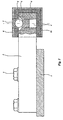
- Figure 1 diagrammatically shows a first embodiment of the construction according to the invention, partly in side view and partly in sectional view.
- Figure 2 diagrammatically shows a second embodiment of the construction according to the invention, partly in sectional view and partly in side view.
- Figure 3 diagrammatically shows a third embodiment of the construction according to the invention, partly in sectional view and partly in side view.
- Figure 4 is a plan view of Figure 3.
- Figure 1 diagrammatically shows a frame 1, which may for example form part of a stationary weighing device or of a vehicle.
- a pressure force indicator 2 also called load cell, which is known per se, is mounted on said frame 1 by means of bolts 3.
- Such a pressure force indicator or load cell is usually provided with strain gauges, which are deformed when the pressure force indicator is loaded and which thereby provide an indication as to the load applied to the pressure force indicator.
- a stepped bore 4 is formed in a free end of the pressure force indicator, in which bore a dish-shaped means 5 is disposed.
- a ball 6 is supported on said dish-shaped means 5.
- Said ball 6 is confined between a supporting surface of dish-shaped means 5 and a supporting surface of another dish-shaped means 7 being supported on said ball.
- Said dish-shaped means 7 is screwed into a threaded bore which is formed in a sleeve-shaped means 8 surrounding the end of the pressure force indicator, said sleeve-shaped means at one end being closed by a vertical wall 9.
- a connecting piece 10 consisting of a resilient material, for example rubber or plastic material, which is confined between the horizontal and vertical boundary surfaces of sleeve-shaped means 8 and pressure force indicator 2.
- Sleeve-shaped means 8 and wall 9 form part of an auxiliary frame, on which a load to be weighed may be placed.
- the construction may thereby be such, that the load to be weighed is weighed by the single pressure force indicator shown in Figure 1, or that more than one pressure force indicator 2 is connected in the manner described above to the auxiliary frame supporting the load.
- FIG 2 shows another embodiment of the construction according to the invention, wherein those parts that correspond with the parts discussed above with reference to Figure 1 are indicated by the same numerals as used in Figure 1.
- a bush 12 is mounted on top of pressure force indicator by means of a bolt 11.
- a dish 5 is housed within a stepped bore formed in bush 12.
- Said dish 5 in turn supports a pressure force-transmitting ball 6, which is confined between dish 5 and a dish 7 positioned above ball 6.
- Dish 7 is provided in a wall 9, which closes sleeve-shaped means 8 at one end.
- the connecting piece 10 which consists of a resilient material such as rubber or the like.
- an attachment of a hard material, such as metal, is slid over the end of pressure force indicator 2, which attachment has a horizontally extending surface at its upper side, but which otherwise tapers off slightly in the direction of a rounded end, which is located more or less in line with the pressure force indicator.
- the attachment is surrounded by a connecting piece 14 consisting of a resilient material, for example rubber or plastic material, which is confined between the outer circumference of attachment 13 and the inner circumference of a sleeve-shaped means 15, which is closed at one end by a vertical wall 16.
- a dish 17 is secured to a part of sleeve-shaped means 15 extending above pressure force indicator 2, with the upper end of a pressure force-transmitting bar 18 being positioned against a supporting surface of said dish.
- Bar 18 extends through a hole 19 formed in attachment 13 into a hole 20 formed in the end of pressure force indicator 20. Said bar 18 is thereby with its bottom end supported on the bottom of blind hole 20, which forms a supporting surface.
- connecting piece 14 consisting of a resilient material, which is confined between rigid members.
Landscapes
- Physics & Mathematics (AREA)
- General Physics & Mathematics (AREA)
- Force Measurement Appropriate To Specific Purposes (AREA)
- Measuring Fluid Pressure (AREA)
- Formation And Processing Of Food Products (AREA)
- Transplanting Machines (AREA)
- Weight Measurement For Supplying Or Discharging Of Specified Amounts Of Material (AREA)
- Medicines Containing Plant Substances (AREA)
- Investigating Strength Of Materials By Application Of Mechanical Stress (AREA)
- Massaging Devices (AREA)
- Diaphragms And Bellows (AREA)
- Measurement Of Force In General (AREA)
- Valve Device For Special Equipments (AREA)
- Feeding, Discharge, Calcimining, Fusing, And Gas-Generation Devices (AREA)
- Confectionery (AREA)
Claims (4)
- Eine Wägevorrichtung zum Wiegen von Ladung, wobei die Wägevorrichtung beinhaltet wenigstens einen Druck-Kraft-Anzeiger (2), welcher verbunden ist mit einem Rahmen (1) und einem Hilfsrahmen (8, 15), an welchem die zu wiegende Ladung platziert ist, wobei eine Druck-Kraft-Übertragungs-Einheit (6,18) zur Kraftübertragung im wesentlichen in vertikaler Richtung angeordnet ist, zwischen besagtem Druck-Kraft-Anzeiger (2) und besagtem Hilfsrahmen (8, 15), welche Druck-Kraft-Übertragungs-Einheit zwischen zwei Stützflächen (5, 7) eingeschlossen ist, wovon eine mit besagtem Druck-Kraft-Anzeiger (2) verbunden ist und die andere mit besagtem Hilfsrahmen (8, 15) verbunden ist, wobei die Teile (8, 2) der Wägevorrichtung, welche besagte Stützflächen stützen, durch ein Verbindungsstück (10, 14) verbunden sind, welches aus einem rückstellfähigen Material besteht, gekennzeichnet darin, dass wenigstens ein Teil von besagtem Verbindungsstück, welches sich in einer im wesentlichen vertikalen Richtung erstreckt, eingeschlossen ist zwischen einem starrem Element (12, 13), welches mit besagter Druck-Kraft-Anzeiger (2) verbunden ist, und einem starren Element (8), welches mit besagtem Hilfsrahmen verbunden ist, so dass jede in einer Richtung auftretende Kraft welche von der vertikalen, abwärts gerichteten Richtung abweicht, auf den Druck-Kraft-Anzeiger, mittels des gespannten, rückstellfähigen Verbindungsstückes (10), übertragen wird.
- Wägevorrichtung nach Anspruch1, dadurch gekennzeichnet, dass ein Ende eines Druck-Kraft-Anzeigers (2) durch eine hülsenförmige Vorrichtung (8,15) umschlossen ist, besagtes Ende in von ihm beabstandeter Anordnung umschließend, welche hülsenförmige Vorrichtung an einem Ende durch eine Wand (9,16) geschlossen ist, besagte Wand von dem Ende des Druck-Kraft-Anzeigers (2) durch einen Abstand beabstandet ist, wobei der Abstand zwischen dem Ende von besagtem Druck-Kraft-Anzeiger (2) und besagter hülsenförmiger Vorrichtung (8,15) und der Wand, welche damit verbunden ist, besagtes Verbindungsstück (10,14) bestehend aus einem rückstellfähigen Material einschließen.
- Eine Wägevorrichtung nach Anspruch 2, dadurch gekennzeichnet, dass ein Anhang an der Endseite des Druck-Kraft-Anzeigers (2) montiert ist, besagter Anhang sich in besagtes Verbindungsstück (14) erstreckt und sich in die Richtung der Wand verjüngt, welche die hülsenförmige Vorrichtung (15) verschließt.
- Eine Wägevorrichtung nach Anspruch 1, dadurch gekennzeichnet, dass eine Buchse (12), welche ein Teil zum Stützen einer Stützfläche (5) ausbildet, an der Oberseite an einem Ende eines Druck-Kraft-Anzeigers (2) montiert ist, besagte Buchse durch eine ihr gegenüber beabstandete hülsenförmige Vorrichtung umschlossen ist, besagte hülsenförmige Vorrichtung an ihrem oberen Ende durch eine Wand (9) verschlossen ist, welche die Stützfläche (7) stützt, besagte Wand vom oberen Ende besagter Hülse (12) durch einen Abstand beabstandet ist, wobei der Raum zwischen der Buchse (12), besagter hülsenförmiger Vorrichtung (8) und der Wand (9), welche besagte hülsenförmige Vorrichtung an einem Ende verschließt, durch besagtes Verbindungsstück (10), bestehend aus einem rückstellfähigen Material, gefüllt ist, wobei wenigstens ein sich vertikal erstreckendes Teil des besagten Verbindungsstücks (10) zwischen den starren Teilen (9,2;8,12;13,16) eingeschlossen ist, welche starr mit besagten, die Stützflächen stützenden Teilen verbunden sind.
Applications Claiming Priority (2)
| Application Number | Priority Date | Filing Date | Title |
|---|---|---|---|
| NL1000432 | 1995-05-24 | ||
| NL1000432A NL1000432C2 (nl) | 1995-05-24 | 1995-05-24 | Weeginrichting. |
Publications (2)
| Publication Number | Publication Date |
|---|---|
| EP0744598A1 EP0744598A1 (de) | 1996-11-27 |
| EP0744598B1 true EP0744598B1 (de) | 2001-11-14 |
Family
ID=19761072
Family Applications (1)
| Application Number | Title | Priority Date | Filing Date |
|---|---|---|---|
| EP96201455A Expired - Lifetime EP0744598B1 (de) | 1995-05-24 | 1996-05-23 | Wägeeinrichtung |
Country Status (6)
| Country | Link |
|---|---|
| EP (1) | EP0744598B1 (de) |
| AT (1) | ATE208890T1 (de) |
| DE (1) | DE69616871T2 (de) |
| DK (1) | DK0744598T3 (de) |
| ES (1) | ES2165953T3 (de) |
| NL (1) | NL1000432C2 (de) |
Cited By (1)
| Publication number | Priority date | Publication date | Assignee | Title |
|---|---|---|---|---|
| US7253366B2 (en) | 2004-08-09 | 2007-08-07 | Hill-Rom Services, Inc. | Exit alarm for a hospital bed triggered by individual load cell weight readings exceeding a predetermined threshold |
Families Citing this family (13)
| Publication number | Priority date | Publication date | Assignee | Title |
|---|---|---|---|---|
| US6924441B1 (en) | 1999-09-29 | 2005-08-02 | Hill-Rom Services, Inc. | Load cell apparatus |
| CA2385825A1 (en) * | 1999-09-29 | 2001-04-05 | Hill-Rom Services, Inc. | Load cell apparatus |
| BE1013185A3 (nl) * | 1999-12-21 | 2001-10-02 | Vliet Ronny Van De | Dubbel buigstaaf weegelement opgebouwd uit twee enkelbuigstaaf krachtopnemers. |
| WO2003001162A1 (en) | 2001-06-22 | 2003-01-03 | Hill-Rom Services, Inc. | Load cell apparatus having gap measuring device |
| DE60210250T2 (de) * | 2001-07-11 | 2007-03-08 | Pm On Board Ltd. | Gerät zum Wiegen einer Ladung |
| BE1015449A3 (nl) * | 2003-04-01 | 2005-04-05 | Vliet Ronny Van De | Rockerpen met geintegreerde begrenzing. |
| BE1016280A3 (nl) * | 2004-01-06 | 2006-07-04 | Vliet Ronny Van De | Weegmodule met geintegreerde horizontale krachtoverdracht. |
| US7176391B2 (en) | 2004-09-13 | 2007-02-13 | Hill-Rom Services, Inc. | Load cell to frame interface for hospital bed |
| US8717181B2 (en) | 2010-07-29 | 2014-05-06 | Hill-Rom Services, Inc. | Bed exit alert silence with automatic re-enable |
| BE1019463A4 (nl) * | 2010-09-01 | 2012-07-03 | Vliet Ronny Van De | Weegmodule met geïntegreerde horizontale en verticale begrenzing. |
| AU2014239599B2 (en) | 2013-03-15 | 2018-08-09 | Stryker Corporation | Medical support apparatus |
| US10330522B2 (en) | 2015-12-17 | 2019-06-25 | Stryker Corporation | Person support apparatus with exit detection system and/or scale system |
| US10898400B2 (en) | 2016-12-01 | 2021-01-26 | Stryker Corporation | Person support apparatuses with load cells |
Family Cites Families (3)
| Publication number | Priority date | Publication date | Assignee | Title |
|---|---|---|---|---|
| US4411327A (en) * | 1981-05-14 | 1983-10-25 | Hottinger Baldwin Measurements, Inc. | Apparatus for applying a load to a strain gage transducer beam |
| CA1249611A (en) * | 1984-10-05 | 1989-01-31 | Franz Balduin | Weighing device |
| EP0476778B1 (de) * | 1990-09-21 | 1995-12-13 | Nv Nuyts Orb | Mobiles Gerät zum Wiegen einer Ladung |
-
1995
- 1995-05-24 NL NL1000432A patent/NL1000432C2/xx not_active IP Right Cessation
-
1996
- 1996-05-23 DK DK96201455T patent/DK0744598T3/da active
- 1996-05-23 ES ES96201455T patent/ES2165953T3/es not_active Expired - Lifetime
- 1996-05-23 AT AT96201455T patent/ATE208890T1/de not_active IP Right Cessation
- 1996-05-23 EP EP96201455A patent/EP0744598B1/de not_active Expired - Lifetime
- 1996-05-23 DE DE69616871T patent/DE69616871T2/de not_active Expired - Lifetime
Cited By (1)
| Publication number | Priority date | Publication date | Assignee | Title |
|---|---|---|---|---|
| US7253366B2 (en) | 2004-08-09 | 2007-08-07 | Hill-Rom Services, Inc. | Exit alarm for a hospital bed triggered by individual load cell weight readings exceeding a predetermined threshold |
Also Published As
| Publication number | Publication date |
|---|---|
| DK0744598T3 (da) | 2002-07-08 |
| EP0744598A1 (de) | 1996-11-27 |
| NL1000432C2 (nl) | 1996-11-26 |
| ATE208890T1 (de) | 2001-11-15 |
| DE69616871D1 (de) | 2001-12-20 |
| ES2165953T3 (es) | 2002-04-01 |
| DE69616871T2 (de) | 2002-08-08 |
Similar Documents
| Publication | Publication Date | Title |
|---|---|---|
| EP0744598B1 (de) | Wägeeinrichtung | |
| US3321035A (en) | Vehicle electronic scales mount | |
| US5600104A (en) | Load cell having reduced sensitivity to non-symmetrical beam loading | |
| EP0524699B1 (de) | Nichtschwingendes Laufrad | |
| CN111999019B (zh) | 一种运营期桥梁支座装置新型标定方法 | |
| WO2012027803A2 (en) | Weighing module for static or dynamic weighing of loads and force transmission applied thereby | |
| EP1111353B1 (de) | Wiegeeinrichtung | |
| US6150619A (en) | Support base for a measuring cell | |
| JPH02146331U (de) | ||
| JP2012117909A (ja) | 複合ロードセル秤 | |
| US4360071A (en) | Sealed load cell construction | |
| US4560017A (en) | Vehicle platform scale | |
| CA2040658A1 (en) | Load sensing assembly | |
| GB2270565A (en) | Weighing machine. | |
| GB2086593A (en) | Weighing device | |
| EP1275943B1 (de) | Gerät zum Wiegen einer Ladung | |
| CN208420147U (zh) | 称重模块 | |
| US7514640B2 (en) | Load beam for a weighing apparatus | |
| US5652411A (en) | Top loading load cell mass comparator | |
| US2666634A (en) | Hydraulic scale check link | |
| JP3654741B2 (ja) | ロードセルの支持構造体 | |
| CN219757482U (zh) | 一种应用于动态秤的称重模组组合装置 | |
| CN214702490U (zh) | 一种防转防倾覆的测力称重模块 | |
| CN106629513A (zh) | 一种免爬设备 | |
| US5078016A (en) | Two piece load cell pin |
Legal Events
| Date | Code | Title | Description |
|---|---|---|---|
| PUAI | Public reference made under article 153(3) epc to a published international application that has entered the european phase |
Free format text: ORIGINAL CODE: 0009012 |
|
| AK | Designated contracting states |
Kind code of ref document: A1 Designated state(s): AT BE CH DE DK ES FI FR GB GR IE IT LI LU MC NL PT SE |
|
| 17P | Request for examination filed |
Effective date: 19970514 |
|
| 17Q | First examination report despatched |
Effective date: 19991116 |
|
| GRAG | Despatch of communication of intention to grant |
Free format text: ORIGINAL CODE: EPIDOS AGRA |
|
| GRAG | Despatch of communication of intention to grant |
Free format text: ORIGINAL CODE: EPIDOS AGRA |
|
| GRAH | Despatch of communication of intention to grant a patent |
Free format text: ORIGINAL CODE: EPIDOS IGRA |
|
| GRAH | Despatch of communication of intention to grant a patent |
Free format text: ORIGINAL CODE: EPIDOS IGRA |
|
| GRAA | (expected) grant |
Free format text: ORIGINAL CODE: 0009210 |
|
| AK | Designated contracting states |
Kind code of ref document: B1 Designated state(s): AT BE CH DE DK ES FI FR GB GR IE IT LI LU MC NL PT SE |
|
| PG25 | Lapsed in a contracting state [announced via postgrant information from national office to epo] |
Ref country code: GR Free format text: LAPSE BECAUSE OF FAILURE TO SUBMIT A TRANSLATION OF THE DESCRIPTION OR TO PAY THE FEE WITHIN THE PRESCRIBED TIME-LIMIT Effective date: 20011114 Ref country code: FI Free format text: LAPSE BECAUSE OF FAILURE TO SUBMIT A TRANSLATION OF THE DESCRIPTION OR TO PAY THE FEE WITHIN THE PRESCRIBED TIME-LIMIT Effective date: 20011114 |
|
| REF | Corresponds to: |
Ref document number: 208890 Country of ref document: AT Date of ref document: 20011115 Kind code of ref document: T |
|
| REG | Reference to a national code |
Ref country code: CH Ref legal event code: EP |
|
| REG | Reference to a national code |
Ref country code: CH Ref legal event code: NV Representative=s name: RITSCHER & SEIFERT |
|
| REG | Reference to a national code |
Ref country code: IE Ref legal event code: FG4D |
|
| REF | Corresponds to: |
Ref document number: 69616871 Country of ref document: DE Date of ref document: 20011220 |
|
| REG | Reference to a national code |
Ref country code: GB Ref legal event code: IF02 |
|
| PG25 | Lapsed in a contracting state [announced via postgrant information from national office to epo] |
Ref country code: PT Free format text: LAPSE BECAUSE OF FAILURE TO SUBMIT A TRANSLATION OF THE DESCRIPTION OR TO PAY THE FEE WITHIN THE PRESCRIBED TIME-LIMIT Effective date: 20020214 |
|
| REG | Reference to a national code |
Ref country code: ES Ref legal event code: FG2A Ref document number: 2165953 Country of ref document: ES Kind code of ref document: T3 |
|
| PG25 | Lapsed in a contracting state [announced via postgrant information from national office to epo] |
Ref country code: MC Free format text: LAPSE BECAUSE OF NON-PAYMENT OF DUE FEES Effective date: 20020523 Ref country code: LU Free format text: LAPSE BECAUSE OF NON-PAYMENT OF DUE FEES Effective date: 20020523 |
|
| REG | Reference to a national code |
Ref country code: DK Ref legal event code: T3 |
|
| PLBE | No opposition filed within time limit |
Free format text: ORIGINAL CODE: 0009261 |
|
| STAA | Information on the status of an ep patent application or granted ep patent |
Free format text: STATUS: NO OPPOSITION FILED WITHIN TIME LIMIT |
|
| 26N | No opposition filed | ||
| PGFP | Annual fee paid to national office [announced via postgrant information from national office to epo] |
Ref country code: ES Payment date: 20050407 Year of fee payment: 10 |
|
| PGFP | Annual fee paid to national office [announced via postgrant information from national office to epo] |
Ref country code: AT Payment date: 20050422 Year of fee payment: 10 |
|
| PGFP | Annual fee paid to national office [announced via postgrant information from national office to epo] |
Ref country code: DK Payment date: 20050523 Year of fee payment: 10 |
|
| PG25 | Lapsed in a contracting state [announced via postgrant information from national office to epo] |
Ref country code: AT Free format text: LAPSE BECAUSE OF NON-PAYMENT OF DUE FEES Effective date: 20060523 |
|
| PG25 | Lapsed in a contracting state [announced via postgrant information from national office to epo] |
Ref country code: ES Free format text: LAPSE BECAUSE OF NON-PAYMENT OF DUE FEES Effective date: 20060524 |
|
| PG25 | Lapsed in a contracting state [announced via postgrant information from national office to epo] |
Ref country code: DK Free format text: LAPSE BECAUSE OF NON-PAYMENT OF DUE FEES Effective date: 20060531 |
|
| REG | Reference to a national code |
Ref country code: DK Ref legal event code: EBP |
|
| REG | Reference to a national code |
Ref country code: ES Ref legal event code: FD2A Effective date: 20060524 |
|
| PGFP | Annual fee paid to national office [announced via postgrant information from national office to epo] |
Ref country code: IE Payment date: 20090529 Year of fee payment: 14 |
|
| PGFP | Annual fee paid to national office [announced via postgrant information from national office to epo] |
Ref country code: IT Payment date: 20090521 Year of fee payment: 14 |
|
| REG | Reference to a national code |
Ref country code: IE Ref legal event code: MM4A |
|
| PG25 | Lapsed in a contracting state [announced via postgrant information from national office to epo] |
Ref country code: IT Free format text: LAPSE BECAUSE OF NON-PAYMENT OF DUE FEES Effective date: 20100523 |
|
| PG25 | Lapsed in a contracting state [announced via postgrant information from national office to epo] |
Ref country code: IE Free format text: LAPSE BECAUSE OF NON-PAYMENT OF DUE FEES Effective date: 20100524 |
|
| REG | Reference to a national code |
Ref country code: NL Ref legal event code: SD Effective date: 20111031 |
|
| REG | Reference to a national code |
Ref country code: CH Ref legal event code: PCAR Free format text: NEW ADDRESS: PESTALOZZISTRASSE 2 POSTFACH 1416, 8201 SCHAFFHAUSEN (CH) |
|
| REG | Reference to a national code |
Ref country code: FR Ref legal event code: PLFP Year of fee payment: 20 |
|
| PGFP | Annual fee paid to national office [announced via postgrant information from national office to epo] |
Ref country code: SE Payment date: 20150520 Year of fee payment: 20 Ref country code: DE Payment date: 20150521 Year of fee payment: 20 Ref country code: GB Payment date: 20150521 Year of fee payment: 20 Ref country code: CH Payment date: 20150521 Year of fee payment: 20 |
|
| PGFP | Annual fee paid to national office [announced via postgrant information from national office to epo] |
Ref country code: BE Payment date: 20150520 Year of fee payment: 20 Ref country code: NL Payment date: 20150520 Year of fee payment: 20 Ref country code: FR Payment date: 20150521 Year of fee payment: 20 |
|
| REG | Reference to a national code |
Ref country code: DE Ref legal event code: R071 Ref document number: 69616871 Country of ref document: DE |
|
| REG | Reference to a national code |
Ref country code: NL Ref legal event code: MK Effective date: 20160522 |
|
| REG | Reference to a national code |
Ref country code: CH Ref legal event code: PL |
|
| REG | Reference to a national code |
Ref country code: GB Ref legal event code: PE20 Expiry date: 20160522 |
|
| PG25 | Lapsed in a contracting state [announced via postgrant information from national office to epo] |
Ref country code: GB Free format text: LAPSE BECAUSE OF EXPIRATION OF PROTECTION Effective date: 20160522 |