EP0744312B1 - Lagerung für eine Antriebseinheit in einem Kraftfahrzeug - Google Patents
Lagerung für eine Antriebseinheit in einem Kraftfahrzeug Download PDFInfo
- Publication number
- EP0744312B1 EP0744312B1 EP96105385A EP96105385A EP0744312B1 EP 0744312 B1 EP0744312 B1 EP 0744312B1 EP 96105385 A EP96105385 A EP 96105385A EP 96105385 A EP96105385 A EP 96105385A EP 0744312 B1 EP0744312 B1 EP 0744312B1
- Authority
- EP
- European Patent Office
- Prior art keywords
- bearing
- clamping
- mounting
- way
- clamping segments
- Prior art date
- Legal status (The legal status is an assumption and is not a legal conclusion. Google has not performed a legal analysis and makes no representation as to the accuracy of the status listed.)
- Expired - Lifetime
Links
Images



Classifications
-
- B—PERFORMING OPERATIONS; TRANSPORTING
- B60—VEHICLES IN GENERAL
- B60K—ARRANGEMENT OR MOUNTING OF PROPULSION UNITS OR OF TRANSMISSIONS IN VEHICLES; ARRANGEMENT OR MOUNTING OF PLURAL DIVERSE PRIME-MOVERS IN VEHICLES; AUXILIARY DRIVES FOR VEHICLES; INSTRUMENTATION OR DASHBOARDS FOR VEHICLES; ARRANGEMENTS IN CONNECTION WITH COOLING, AIR INTAKE, GAS EXHAUST OR FUEL SUPPLY OF PROPULSION UNITS IN VEHICLES
- B60K5/00—Arrangement or mounting of internal-combustion or jet-propulsion units
- B60K5/12—Arrangement of engine supports
- B60K5/1208—Resilient supports
- B60K5/1216—Resilient supports characterised by the location of the supports relative to the motor or to each other
-
- F—MECHANICAL ENGINEERING; LIGHTING; HEATING; WEAPONS; BLASTING
- F16—ENGINEERING ELEMENTS AND UNITS; GENERAL MEASURES FOR PRODUCING AND MAINTAINING EFFECTIVE FUNCTIONING OF MACHINES OR INSTALLATIONS; THERMAL INSULATION IN GENERAL
- F16F—SPRINGS; SHOCK-ABSORBERS; MEANS FOR DAMPING VIBRATION
- F16F15/00—Suppression of vibrations in systems; Means or arrangements for avoiding or reducing out-of-balance forces, e.g. due to motion
- F16F15/02—Suppression of vibrations of non-rotating, e.g. reciprocating systems; Suppression of vibrations of rotating systems by use of members not moving with the rotating systems
- F16F15/04—Suppression of vibrations of non-rotating, e.g. reciprocating systems; Suppression of vibrations of rotating systems by use of members not moving with the rotating systems using elastic means
-
- F—MECHANICAL ENGINEERING; LIGHTING; HEATING; WEAPONS; BLASTING
- F16—ENGINEERING ELEMENTS AND UNITS; GENERAL MEASURES FOR PRODUCING AND MAINTAINING EFFECTIVE FUNCTIONING OF MACHINES OR INSTALLATIONS; THERMAL INSULATION IN GENERAL
- F16F—SPRINGS; SHOCK-ABSORBERS; MEANS FOR DAMPING VIBRATION
- F16F7/00—Vibration-dampers; Shock-absorbers
- F16F7/10—Vibration-dampers; Shock-absorbers using inertia effect
- F16F7/104—Vibration-dampers; Shock-absorbers using inertia effect the inertia member being resiliently mounted
-
- B—PERFORMING OPERATIONS; TRANSPORTING
- B60—VEHICLES IN GENERAL
- B60G—VEHICLE SUSPENSION ARRANGEMENTS
- B60G2202/00—Indexing codes relating to the type of spring, damper or actuator
- B60G2202/20—Type of damper
- B60G2202/25—Dynamic damper
Definitions
- the invention relates to a bearing for a drive unit in one Motor vehicle according to the preamble of claim 1.
- a drive unit for a motor vehicle is known a front bearing for the engine and a rear bearing for the transmission - in with respect to the direction of travel.
- the bearings are arranged in this way and designed so that the drive unit can act as an absorber to To reduce body vibrations as much as possible.
- the object of the invention is to provide improved storage for a drive unit create a structurally simple warehouse structure with quick to assemble Components includes.
- the only one Engine mounts as well as the gearbox mounts consist of components that are easy to assemble or quickly and easily accessible on the drive unit and on Vehicle body to be fastened.
- the engine mount consists of a bearing plate with a holder for the bearing, which is fixed in a mounting plate on the body side insertable between two legs and held by two screws.
- the storage for the gearbox is constructed so that a simple and quick assembly is guaranteed.
- the sheet metal bearing arms protruding from the housing are upright arranged and are supported on the body side in elastic bearings and on Gearbox detachable by means of an angled bridge Clamping segments existing fixture attached.
- This holding device Has the advantage of the possibility of a simple pre-assembly, compensation of tolerances and Furthermore, the leaf spring-like bearing arms can be in Deflect vehicle longitudinal direction during operation. By training the Clamping segments with a in the radius area of the angled web of the Bearing arm arranged rounded edge or nose-shaped edge is the Bearing arm supported in this area for longitudinal bending.
- the Holding device made of sheet metal arms, which are also designed like leaf spring and which are connected with an adapter made of a light metal die casting.
- the adapter has protruding tongues to accommodate and fix the bearing arms, which accommodate the free ends of the sheet steel bearing arms in a slot can.
- the bearing arms of the two versions each have two individual, one free space between the arms, which are connected at the end with the adapter via rivets, Screws or the like. Connection means are connected. They are also corresponding Bearing arms of the further embodiment formed, in the area of Clamping elements a web can connect the two bearing arms to each other.
- Fig. 1 is a drive unit 1, consisting of an internal combustion engine 2 and a transmission 3 shown. Via an engine mounting 4, consisting of a single elastic bearing 5 and a gearbox mounting 6, which two transverse bearing arms 7, 8 each with an end elastic bearing 9, 10, the drive unit 1 is supported on the vehicle body and can be as Absorber mass act.
- the internal combustion engine 2 is designed as a boxer engine and as a central engine in the Vehicle arranged.
- the bearing 4 for the engine is just behind the one arranged front seat row vehicle and the elastic bearing 4 is in a vertical center plane X-X of a crankshaft of the engine.
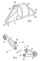
- the engine mounting 4 according to FIGS. 2 and 3 includes one with the vehicle body connected carrier plate 11 between upright legs 12, 13 a resilient bearing 14, which in a protruding receptacle 15 a Bearing plate 16 is arranged.
- the bearing plate 16 is trapezoidal, has lower corner points 17, 17a Bores 18 for fastening screws for connecting to the motor housing. So that easy assembly is possible in the very confined spaces, has the bearing plate 16 in an upper corner 19 an open to the outside Cross slot 20 in which a fastening screw is held.
- a first transmission mounting 6 for a manual transmission (Fig. 4 to 7) comprises the Bearing arms 7, 8. These are for attachment to the gear housing with a angled web 21 provided between one of the clamping segments 22, 23 Holding device H is held clamped. There are two for each bearing arm 7, 8 Clamping segments 22, 23 arranged one above the other are provided, as shown in FIG. 7 in more detail shows.
- the clamping segments 22, 23 are each of the same shape, the parts Envelope, i.e. to each other, offset by 180 ° via a fastening screw 24 can be fastened together with the bearing arms 7, 8 on the gear housing.
- the clamping segment 22 and 23 has an edge 25 of its clamping surface nose-shaped projection 26 with an inner radius 27.
- the opposite Edge 28 is provided with an outer radius 29.
- the radii 27 and 29 correspond the inner radius or the outer radius of the angled web 21 of the bearing arms 7, 8.
- FIG. 6 shows in more detail, the formation of the inner and outer radii 27, 29 the bending edge 30 of the bearing arm web 21 encompassed so that in the event of longitudinal bends Bearing arm 7, 8 in directions A and B support is achieved.
- the two clamping segments 22, 23 are in position with respect to one another via a bushing 31 held and at the same time they form a protection against loss.
- FIGS. 8 and 9 Another gearbox mounting 6a for an automatic gearbox is shown in FIGS. 8 and 9 shown. Because the weight of the automatic transmission is much heavier than is a manual transmission, the storage is also more stable.
- This bearing 6a includes a three screws on the gear housing attached holding device H1, which consists of an adapter 33, which consists of a light metal die casting is formed.
- the mounting screws 34 to 36 are only indicated as center lines.
- the bearing arms 7a, 8a are thin, upright sheets, similar to leaf springs, executed, as well as the bearing arms 7, 8 for the manual transmission. Are at each end the elastic bearings 9, 10 arranged.
- the connection to the adapter 33 is made via two connections 37, 38, which consist of a rivet or a screw can.
- the free ends 39, 40 of the bearing arms 7a, 8a are transverse in slots 41 protruding tongues 42 of the adapter 33 arranged.
- the slots 41 are wedge-shaped outwardly widened, i.e. the free ends are easy importable.
- the wedge-shaped slot becomes by fastening via rivets or the like drawn together.
- a holder for hanging to accommodate an abutment W 3 a cable is provided, which is molded onto the adapter.
Landscapes
- Engineering & Computer Science (AREA)
- General Engineering & Computer Science (AREA)
- Mechanical Engineering (AREA)
- Chemical & Material Sciences (AREA)
- Combustion & Propulsion (AREA)
- Transportation (AREA)
- Physics & Mathematics (AREA)
- Acoustics & Sound (AREA)
- Aviation & Aerospace Engineering (AREA)
- Arrangement Or Mounting Of Propulsion Units For Vehicles (AREA)
- Arrangement Of Transmissions (AREA)
Description
Es zeigen:
- Fig. 1
- eine Draufsicht auf eine schematisch dargestellte Antriebseinheit mit Motorlagerung und Getriebelagerung,
- Fig. 2
- eine schaubildliche Darstellung einer Motorlagerung, bestehend aus einer Lager- und Trägerplatte,
- Fig. 3
- eine schaubildliche Darstellung der Lagerplatten,
- Fig. 4
- eine schaubildliche Darstellung auf die Getriebelagerung für ein Schaltgetriebe,
- Fig. 5
- eine Draufsicht auf einen Lagerarm einer Getriebelagerung gem. Fig. 4 mit elastischen Lager- und Klemmsegmenten,
- Fig. 6
- eine Ansicht auf die Klemmsegmente,
- Fig. 7
- einen Schnitt nach der Linie VII-VII durch die Klemmsegmente,
- Fig. 8
- eine schaubildliche Darstellung auf die Getriebelagerung für ein automatisches Getriebe und
- Fig. 9
- eine Draufsicht auf die Getriebelagerung gem. Fig. 8.
Claims (3)
- Lagerung für eine Antriebseinheit (1) in einem Kraftfahrzeug, die über ein vorderes einziges Lager (4), gehalten ist und eine weitere Lagerung (9, 10) zu beiden Seiten eines Getriebegehäuses vorgesehen ist, die aus quer wegragenden Lagerarmen (7, 8) besteht, welche endseitig elastische Lagerelemente (9, 10) aufnehmen, und daß die Lagerarme (7, 8) des Getriebegehäuses (6; 6a) in Längsrichtung biegeweich ausgeführt sind und über eine Halteeinrichtung (H) am Getriebegehäuse festsetzbar sind, dadurch gekennzeichnet, daß die Halteeinrichtung (H) aus zwei Klemmsegmenten (22, 23) besteht, die zwischen sich jeweils einen abgewinkelten Steg (21) des Lagerarmes (7, 8) aufnehmen und beide Klemmsegmente (22, 23) über eine Schraube (24) am Getriebegehäuse befestigbar sind und aus formgleich ausgebildeten Teilen bestehen und im Einbauzustand auf Umschlag um 180° versetzt zueinander verbaut angeordnet sind und die Klemmsegmente (22, 23) eine abgerundete Außenkante (29) und gegenüberliegend eine nasenförmige Ausformung (26) mit innenseitig ausgerundeter Kante (27) aufweisen.
- Lagerung nach Anspruch 1, dadurch gekennzeichnet, daß im Einbauzustand die nasenförmige Ausformung (26) des einen Klemmsegments (23) den abgewinkelten Steg (21) des Lagerarmes (7, 8) von außen übergreift und die abgerundete Kante (29) des weiteren innenliegenden Klemmsegments (22) in der Rundung des abgewinkelten Steges (21) liegt und der nasenförmigen Ausformung (26) des außenliegenden Klemmelements (23) gegenübersteht.
- Lagerung nach Anspruch 1 oder einem der vorhergehenden Ansprüche, dadurch gekennzeichnet, daß die Klemmsegmente (22, 23) über eine Buchse (31) in der die Befestigungsschraube (24) angeordnet ist, zueinander in Lage gehalten sind.
Applications Claiming Priority (2)
| Application Number | Priority Date | Filing Date | Title |
|---|---|---|---|
| DE19518576 | 1995-05-20 | ||
| DE19518576A DE19518576C1 (de) | 1995-05-20 | 1995-05-20 | Lagerung für eine Antriebseinheit in einem Kraftfahrzeug |
Publications (3)
| Publication Number | Publication Date |
|---|---|
| EP0744312A2 EP0744312A2 (de) | 1996-11-27 |
| EP0744312A3 EP0744312A3 (de) | 1997-10-08 |
| EP0744312B1 true EP0744312B1 (de) | 2001-01-10 |
Family
ID=7762444
Family Applications (1)
| Application Number | Title | Priority Date | Filing Date |
|---|---|---|---|
| EP96105385A Expired - Lifetime EP0744312B1 (de) | 1995-05-20 | 1996-04-04 | Lagerung für eine Antriebseinheit in einem Kraftfahrzeug |
Country Status (2)
| Country | Link |
|---|---|
| EP (1) | EP0744312B1 (de) |
| DE (2) | DE19518576C1 (de) |
Families Citing this family (3)
| Publication number | Priority date | Publication date | Assignee | Title |
|---|---|---|---|---|
| DE102004058125B4 (de) * | 2004-12-02 | 2007-02-01 | Dr.Ing.H.C. F. Porsche Ag | Lagereinrichtung für eine Antriebseinheit eines Kraftfahrzeugs |
| DE102009060484B4 (de) * | 2009-12-18 | 2020-04-16 | Pinion Gmbh | Mit Muskelkraft antreibbares Fahrzeug |
| CN106696668A (zh) * | 2016-12-28 | 2017-05-24 | 云南力帆骏马车辆有限公司 | 一种发动机后支承装置及载货汽车 |
Family Cites Families (3)
| Publication number | Priority date | Publication date | Assignee | Title |
|---|---|---|---|---|
| FR1194470A (fr) * | 1958-01-10 | 1959-11-10 | Simca Automobiles Sa | Perfectionnements à la fixation du moteur et des organes de transmission de la puissance sur les véhicules automobiles |
| JP2804666B2 (ja) * | 1991-06-05 | 1998-09-30 | ダイハツ工業株式会社 | 車両用エンジンのマウント装置 |
| DE4307999A1 (de) * | 1993-03-13 | 1994-09-15 | Porsche Ag | Kraftfahrzeug |
-
1995
- 1995-05-20 DE DE19518576A patent/DE19518576C1/de not_active Expired - Fee Related
-
1996
- 1996-04-04 DE DE59606288T patent/DE59606288D1/de not_active Expired - Fee Related
- 1996-04-04 EP EP96105385A patent/EP0744312B1/de not_active Expired - Lifetime
Also Published As
| Publication number | Publication date |
|---|---|
| EP0744312A2 (de) | 1996-11-27 |
| EP0744312A3 (de) | 1997-10-08 |
| DE59606288D1 (de) | 2001-02-15 |
| DE19518576C1 (de) | 1996-10-31 |
Similar Documents
| Publication | Publication Date | Title |
|---|---|---|
| DE3700761C2 (de) | ||
| DE3909458B4 (de) | Kettenradhalterungs- und Kettenführungselement | |
| EP1021321B1 (de) | Scheibenwischeranlage für fahrzeuge | |
| EP0050722B1 (de) | Stossfänger für Fahrzeuge, insbesondere für Kraftfahrzeuge | |
| EP3181390B1 (de) | Fahrzeug mit einem antriebsaggregat und einer aggregatelagerung | |
| DE3927485A1 (de) | Vorrichtung bzw. montagebaugruppe zwischen motor- bzw. antriebseinheit und fahrgestell eines kraftfahrzeugs | |
| EP0054880A1 (de) | Vibrationsgedämpfte Sitzlagerung | |
| DE19613870C2 (de) | Fangvorrichtung für ein Antriebsaggregat | |
| DE3840501A1 (de) | Verfahren zur montage einer wischanlage und wischanlage | |
| EP1023208B1 (de) | Befestigungsvorrichtung für eine scheibenwischeranlage | |
| DE69604897T2 (de) | Trägerplatte eines scheibenwischer-mechanismus | |
| DE19518576C1 (de) | Lagerung für eine Antriebseinheit in einem Kraftfahrzeug | |
| DE3822055A1 (de) | Haltevorrichtung | |
| DE3115394C2 (de) | ||
| DE454661C (de) | Tragblattfeder fuer Kraftfahrzeuge | |
| WO2002081259A1 (de) | Fahrzeugsitz mit lagervorrichtung | |
| DE19939304B4 (de) | Lagerung für eine Antriebseinheit | |
| EP3964369B1 (de) | Montagesystem | |
| DE3008872A1 (de) | Vorrichtung zum befestigen eines behaelters in einem kraftfahrzeugmotorraum | |
| EP1242268A2 (de) | Befestigungsanordnung für eine scheibenwischeranlage an einer fahrzeugkarosserie | |
| DE10356945B4 (de) | Halterung eines Kühlers | |
| DE102004034074A1 (de) | Antriebslagerung für einen Kraftwagen | |
| DE2229663A1 (de) | Federnde achsaufhaengung fuer kraftfahrzeuge | |
| AT504061B1 (de) | Flexibles hängungssystem für schwere hängungen im untergestell | |
| DE3322364C2 (de) | Aufhängevorrichtung für eine Abgasanlage eines Kraftwagens |
Legal Events
| Date | Code | Title | Description |
|---|---|---|---|
| PUAI | Public reference made under article 153(3) epc to a published international application that has entered the european phase |
Free format text: ORIGINAL CODE: 0009012 |
|
| AK | Designated contracting states |
Kind code of ref document: A2 Designated state(s): DE FR GB IT |
|
| PUAL | Search report despatched |
Free format text: ORIGINAL CODE: 0009013 |
|
| AK | Designated contracting states |
Kind code of ref document: A3 Designated state(s): DE FR GB IT |
|
| 17P | Request for examination filed |
Effective date: 19980312 |
|
| 17Q | First examination report despatched |
Effective date: 19990628 |
|
| GRAG | Despatch of communication of intention to grant |
Free format text: ORIGINAL CODE: EPIDOS AGRA |
|
| GRAG | Despatch of communication of intention to grant |
Free format text: ORIGINAL CODE: EPIDOS AGRA |
|
| GRAH | Despatch of communication of intention to grant a patent |
Free format text: ORIGINAL CODE: EPIDOS IGRA |
|
| GRAH | Despatch of communication of intention to grant a patent |
Free format text: ORIGINAL CODE: EPIDOS IGRA |
|
| ITF | It: translation for a ep patent filed | ||
| GRAA | (expected) grant |
Free format text: ORIGINAL CODE: 0009210 |
|
| AK | Designated contracting states |
Kind code of ref document: B1 Designated state(s): DE FR GB IT |
|
| GBT | Gb: translation of ep patent filed (gb section 77(6)(a)/1977) |
Effective date: 20010118 |
|
| REF | Corresponds to: |
Ref document number: 59606288 Country of ref document: DE Date of ref document: 20010215 |
|
| ET | Fr: translation filed | ||
| PLBE | No opposition filed within time limit |
Free format text: ORIGINAL CODE: 0009261 |
|
| STAA | Information on the status of an ep patent application or granted ep patent |
Free format text: STATUS: NO OPPOSITION FILED WITHIN TIME LIMIT |
|
| REG | Reference to a national code |
Ref country code: GB Ref legal event code: IF02 |
|
| 26N | No opposition filed | ||
| PGFP | Annual fee paid to national office [announced via postgrant information from national office to epo] |
Ref country code: GB Payment date: 20040414 Year of fee payment: 9 |
|
| PGFP | Annual fee paid to national office [announced via postgrant information from national office to epo] |
Ref country code: DE Payment date: 20040420 Year of fee payment: 9 |
|
| PGFP | Annual fee paid to national office [announced via postgrant information from national office to epo] |
Ref country code: FR Payment date: 20040428 Year of fee payment: 9 |
|
| PG25 | Lapsed in a contracting state [announced via postgrant information from national office to epo] |
Ref country code: IT Free format text: LAPSE BECAUSE OF NON-PAYMENT OF DUE FEES Effective date: 20050404 Ref country code: GB Free format text: LAPSE BECAUSE OF NON-PAYMENT OF DUE FEES Effective date: 20050404 |
|
| PG25 | Lapsed in a contracting state [announced via postgrant information from national office to epo] |
Ref country code: DE Free format text: LAPSE BECAUSE OF NON-PAYMENT OF DUE FEES Effective date: 20051101 |
|
| GBPC | Gb: european patent ceased through non-payment of renewal fee |
Effective date: 20050404 |
|
| PG25 | Lapsed in a contracting state [announced via postgrant information from national office to epo] |
Ref country code: FR Free format text: LAPSE BECAUSE OF NON-PAYMENT OF DUE FEES Effective date: 20051230 |
|
| REG | Reference to a national code |
Ref country code: FR Ref legal event code: ST Effective date: 20051230 |