EP0744247B1 - Schleifwerkzeug, insbesondere Trennschleifwerkzeug und Verfahren zur Herstellung eines solchen Werkzeuges - Google Patents
Schleifwerkzeug, insbesondere Trennschleifwerkzeug und Verfahren zur Herstellung eines solchen Werkzeuges Download PDFInfo
- Publication number
- EP0744247B1 EP0744247B1 EP96200066A EP96200066A EP0744247B1 EP 0744247 B1 EP0744247 B1 EP 0744247B1 EP 96200066 A EP96200066 A EP 96200066A EP 96200066 A EP96200066 A EP 96200066A EP 0744247 B1 EP0744247 B1 EP 0744247B1
- Authority
- EP
- European Patent Office
- Prior art keywords
- zone
- core
- hardness
- cut
- steel
- Prior art date
- Legal status (The legal status is an assumption and is not a legal conclusion. Google has not performed a legal analysis and makes no representation as to the accuracy of the status listed.)
- Expired - Lifetime
Links
Images


Classifications
-
- B—PERFORMING OPERATIONS; TRANSPORTING
- B24—GRINDING; POLISHING
- B24D—TOOLS FOR GRINDING, BUFFING OR SHARPENING
- B24D3/00—Physical features of abrasive bodies, or sheets, e.g. abrasive surfaces of special nature; Abrasive bodies or sheets characterised by their constituents
- B24D3/02—Physical features of abrasive bodies, or sheets, e.g. abrasive surfaces of special nature; Abrasive bodies or sheets characterised by their constituents the constituent being used as bonding agent
- B24D3/04—Physical features of abrasive bodies, or sheets, e.g. abrasive surfaces of special nature; Abrasive bodies or sheets characterised by their constituents the constituent being used as bonding agent and being essentially inorganic
- B24D3/06—Physical features of abrasive bodies, or sheets, e.g. abrasive surfaces of special nature; Abrasive bodies or sheets characterised by their constituents the constituent being used as bonding agent and being essentially inorganic metallic or mixture of metals with ceramic materials, e.g. hard metals, "cermets", cements
-
- B—PERFORMING OPERATIONS; TRANSPORTING
- B24—GRINDING; POLISHING
- B24D—TOOLS FOR GRINDING, BUFFING OR SHARPENING
- B24D18/00—Manufacture of grinding tools or other grinding devices, e.g. wheels, not otherwise provided for
- B24D18/0009—Manufacture of grinding tools or other grinding devices, e.g. wheels, not otherwise provided for using moulds or presses
-
- B—PERFORMING OPERATIONS; TRANSPORTING
- B24—GRINDING; POLISHING
- B24D—TOOLS FOR GRINDING, BUFFING OR SHARPENING
- B24D5/00—Bonded abrasive wheels, or wheels with inserted abrasive blocks, designed for acting only by their periphery; Bushings or mountings therefor
- B24D5/12—Cut-off wheels
-
- B—PERFORMING OPERATIONS; TRANSPORTING
- B28—WORKING CEMENT, CLAY, OR STONE
- B28D—WORKING STONE OR STONE-LIKE MATERIALS
- B28D1/00—Working stone or stone-like materials, e.g. brick, concrete or glass, not provided for elsewhere; Machines, devices, tools therefor
- B28D1/02—Working stone or stone-like materials, e.g. brick, concrete or glass, not provided for elsewhere; Machines, devices, tools therefor by sawing
- B28D1/12—Saw-blades or saw-discs specially adapted for working stone
- B28D1/121—Circular saw blades
Definitions
- the invention relates to a cut-off tool with a steel support body and a directly attached to it by sintering, preferably diamond as abrasive grains in a sintered bond containing, segmented or non-segmented Abrasive coating, the sintered bond consisting of one or more high-melting Metals such as cobalt, iron or the like.
- the invention relates further a method for producing a cut-off tool.
- Cut-offs with such tools with manually operated machines is very often at 80 m / s peripheral speed of the tool and in Dry cut performed.
- the requirements for the connection of the diamond-containing Abrasive pads with the steel carrier body are so high that soldering for reasons of occupational safety due to insufficient heat resistance is no longer sufficient.
- the permanent connection of Abrasive coating and carrier body well introduced by laser beam welding.
- the high energy concentration on the narrowly defined welding zone in the laser beam thereby a weldability of carrier steel up to a maximum of approximately 0.25 percent by weight carbon, without affecting the material fixed strength levels through new hardening or tempering processes.
- Laser beam welding technology has become particularly popular in the medium diameter range the hand-held abrasive inserts on natural and artificial stone have proven their worth. Characteristic nominal diameters of the middle working area are between 180 and 300 mm in diameter. It has by laser beam welding enables the dynamic strength of work hardened or cold hardened to be exploited Carrier steel materials with up to 0.25 weight percent carbon a beneficial effect on the applicability of these tools for high-performance dry cutting of stone materials.
- JP-A-61 257777 (Osaka Diamond) strikes iron as a binding agent or an intermediate layer of iron Cutting surface and steel support body in front. At least binding mixtures are said to Iron base increase weldability. Even soldering trained in this way Cutting segments with the steel support body are said to be according to this publication be improved.
- US-A-4624237 shows some embodiments of cut-off tools, which is a permanent connection of the abrasive coating to the steel support body by direct sintering.
- the different embodiments of abrasive pads in it intend for improved air circulation and thus improved sanding dust removal through side recesses in the base and carrier body.
- the recesses in the abrasive coating in the carrier body continue, which should also give the advantage of stiffening.
- stiffening is only possible if a higher sheet thickness is provided which increases the moment of resistance to bending and not by removing material in the grooves of the side surfaces of the carrier body given sheet thickness.
- Cut-off tools of this type are this publication in the medium diameter range up to 300 mm. A segmented covering and Soldering proposed according to the prior art.
- the invention has for its object, abrasive tools of the beginning described type to improve so that with relatively low manufacturing Effort, a reduction in production time and thus a reduction in manufacturing costs of high-performance abrasive cut-off tools to provide.
- the improvement relates on the wear resistance in the edge of the carrier body close to the abrasive coating compared to the stock removal products, on the flexural fatigue strength of the carrier body and on the safety of the permanent connection between the grinding part and carrier body, especially in the nominal diameter range of the tools larger than 125 mm.
- the invention is also based on the object of specifying a method with which the inventive abrasive cutters are simple and inexpensive can be produced.
- the carrier body is preferably made of a steel of the types made according to claim 4.
- the Selection of the steel raw material plays a crucial role in the adoption the intended hardness in the different zones of the carrier body.
- the Invention is based on the knowledge that an increase in hardness in the abrasive coating Zone and an increase in the dynamic fatigue strength of the Tool in the application primarily by increasing the carbon content must be achieved. Such an increase in carbon content however, includes a welding process for connection to the abrasive coating out. It is therefore provided according to the invention that the grinding of the abrasive coating bond by pressure sintering, the permanent fastening of the grinding surface on the steel support body by pressure sintering and hardening the steel of the support body from the temperature of the pressure sintering in one operation.
- the nickel alloyed tempering steels in particular enable the characteristics of Subject of the invention.
- tempered steels with a combination can also be used of 2 or more of those that increase through-pay and temper resistance Alloy elements such as chromium, nickel, molybdenum and vanadium according to the invention be provided. It is important that the favorable properties of these alloy elements on the through hardenability and temper resistance, as you would of large, dynamically stressed components in the tempered condition are known on the extremely thin-walled components as they Represent carrier body for abrasive tools, be transferable.
- the invention has recognized that the high quality tempered steels, which are usually in distant application areas, for example in mechanical engineering, are used as sheet steel for the production of Cut-off tools with their characteristic extreme ratio of Diameters to thickness are more appropriate if a suitable manufacturing process can be found.
- the method can also be carried out so that for the purpose of cooling the bore side Area of the support body for support and smoothing the production of a coolant flow through the press plates is.
- the invention teaches that slow, continuous cooling, such as it occurs in a thick-walled component for the new hardening of the abrasive lining side Zone of the support body can be used. It is enough the air tempering property of the carrier steel according to the invention Hardness assumption with air or compressed air cooling of the sintering die, which is the final pressed Cut-off tool after switching off the inductive heat source still contains. According to the invention it can also be provided that the press ram to make production more even and faster Coolant channels are cooled internally.
- machine-like and device-like are within the scope of the invention Additions or refinements possible. This applies in particular to Workpiece feed and removal and structural details of the pressing and clamping tools of the individual process steps.
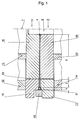
- the sintering press mold shown in FIG. 1 is the main component of a pressure sintering press.
- the main components of the sintering die are a press ring (15) to form the peripheral contour of the abrasive coating (5), an upper press ram (17) and a lower press ram (19) for pressure sintering of the green abrasive coating (6) up to the stop on the carrier body (4) in a zone (2).
- the pressure sintering process simultaneously becomes the carrier body (4) in the region of the zone (2) and the abrasive coating (5) in the region of the zone (1) to approximately the same temperature brought.
- the inner press plates (16, 18) come immediately at the start of Pressure sintering process for contact in the zone (3) of the carrier body (4) through the inner press blocks (11 and 13). This will make the pre-made blank of the abrasive cutting tool, consisting of the carrier body (4) and the Grinding pad green (6) positioned in the sintering mold.
- the actuation of the Sintering press is carried out separately by the outer press blocks (12, 14) opposite the inner press blocks (11, 13).
- a production method according to the invention is schematically taken into account in FIG. 1 with the possibility of separate, targeted heat treatment in each Zones (2) and (3) of the carrier body (4) and for the simultaneous pressure sintering of the abrasive green sheet (6) in zone (1).
- the manufacturing process begins with the with respect to the tool axis (7) concentric insertion over the mandrel (8) blanks of the abrasive tool manufactured according to the prior art, consisting of a steel support body and one with the usual temporary Binder-provided, cold-pressed green abrasive coating (6), wherein as usual, on the outer circumference of the carrier body (4) a toothing or the whole or part of the radial expansion of the abrasive coating green (6) can protrude.
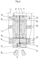
- FIG. 2 shows the abrasive cutting tool according to the invention in the stage towards the end of pressure sintering and simultaneous heating to the austenitizing temperature in the zone (2) of the carrier body (4) close to the abrasive coating.
- the inductor coil (22) heats the press rams (17, 19), the press ring (15) and especially the zone (2) of the support body (4) close to the abrasive coating and the abrasive coating (5) to approximately the same temperature level, whereby the above Components are coupled to one thermal unit and opposite the second thermal unit consisting of the two press plates (16, 18) with in between Zone (3) of the carrier body (4) located in close contact is decoupled.
- zone (2) of the carrier body (4) passes through continuous cooling in air or with compressed air support from the sintering or Austenitization temperature is hardened.
- a Steel can be selected as the carrier body material, which is characterized by a high hardenability distinguished, which at a cooling rate of less than 200 ° C. per minute in the range between austenitizing temperature and 250 ° C have to be. This corresponds to a continuous cooling time of more than 3 minutes.
- Such changes or adjustments can for example depending on the nominal diameter of the tool, but also depending on the shape of the abrasive coating (5). That's the radius the separation gap (23) between the press rams (17, 19) and the press plates (16, 18) to be chosen smaller than the smallest radius with respect to the tool axis (7), formed by the relaxation openings (24) with a segmented abrasive coating (5).
- Another possible embodiment of the invention is based on a one-piece Mold lower part and a one-piece upper mold part in the form that the two Press (17) and (19) to the mandrel (8).
- the manufacturing process according to the invention can thereby be made in one piece (10) and carried out in a one-piece mold lower part (9) without a separation gap (23) become.
- the heating up times to pressure sintering and Hardening temperature according to the increased mass of the material to be heated Molding material.
- Manufacturing process can be a part of the lower mold part (9) and the upper mold part (10), starting from the receiving bore area of the carrier body (4) additionally be provided with coolant holes (21) through which a constant or, depending on the press cycle, flow can be shut off with a Coolant can take place as shown schematically in FIG. 3.
- Fig. 4 shows the course of temperature and hardness over the diameter of the Cut-off tool of a production example.
- the QT curve for the Hardening temperature shows the approximate synchronization of the temperature during the Internal pressure in the abrasive coating (5) corresponding to zone (1) and in zone (2) of the Carrier body (4).
- the tool had a nominal diameter of 230 mm and a carrier body thickness of 1.6 mm, a bore of 22.23 mm and had 18 cutting segments which were spaced apart by the expansion openings.
- the segment height was 5 mm and the segment width was 2.4 mm.
- a round blank made of 50CrV4 steel according to Euronorm was used as the primary body material with the fabric no. 1.8159 used in the condition at 37 HRC.
- the scope the blank was chamfered as usual to strengthen the adhesion to the abrasive coating and knurled, but not yet provided with the relaxation openings.
- the binding mixture contained diamond abrasive grain of the grain size FEPA D601 of type SDA DXTY from De Beers, the amount being concentrated of 0.8 carats per cubic centimeter of sanding on the end product has been.
- the sinter powder for the binding was "Cobalt extra fine" from Hoboken.
- Zone 1 and Zone 2 were inductively heated within 8 minutes to 850 C. Then a sintering pressure of 230 kN was applied and 4 minutes kept at 850 C.
- the tool was cooled down continuously within the press ram with compressed air to 250 C within 8 minutes.
- the hardness in the re-hardening area of the steel carrier body was then 37 to 40 HRC and in the bore area according to the raw material condition 37 HRC.
- the tools according to the invention enable high-durability construction of the carrier body, due to increased wear protection against abrasion without additional constructive measures in the edge zone of the carrier body. This affects when processing asphalt, concrete and the like particularly cheap.
- the increased dynamic rigidity of the invention Tools through the high quality used, tempered to high hardness values Carrier body steel allows high cutting performance and thus easier work for the user.
- a complete production stage is omitted in the manufacturing method according to the invention like the separate joining process of soldering or welding.
- the heightened Costs for the steel raw material can be eliminated by eliminating separate joining costs be more than balanced.
- the usual facilitation of the joining process through the arrangement of non-abrasive intermediate layers in the abrasive coating can be omitted.
Landscapes
- Engineering & Computer Science (AREA)
- Mechanical Engineering (AREA)
- Chemical & Material Sciences (AREA)
- Ceramic Engineering (AREA)
- Inorganic Chemistry (AREA)
- Manufacturing & Machinery (AREA)
- Mining & Mineral Resources (AREA)
- Polishing Bodies And Polishing Tools (AREA)
- Turning (AREA)
- Mechanical Treatment Of Semiconductor (AREA)
Description
- 1
- Zone 1
- 2
- Zone 2
- 3
- Zone 3
- 4
- Trägerkörper
- 5
- Schleifbelag
- 6
- Schleifbelagsgrünling
- 7
- Werkzeugachse
- 8
- Dorn
- 9
- Formunterteil
- 10
- Formoberteil
- 11
- Preßklotz innen oben
- 12
- Preßklotz außen oben
- 13
- Preßklotz innen unten
- 14
- Preßklotz außen unten
- 15
- Preßring
- 16
- Preßplatte innen unten
- 17
- Preßstempel außen unten
- 18
- Preßplatte innen oben
- 19
- Preßstempel außen oben
- 20
- Düse
- 21
- Kühlmittelbohrung
- 22
- Induktorspule
- 23
- Trennspalt
- 24
- Entspannungsöffnung
- 25
- Aufnahmebohrung
- D
- Nenndurchmesser
- AT
- Anlaßtemperatur
- QT
- Härtetemperatur
- AH
- Anlaßhärte
- QH
- Ansprunghärte
Claims (7)
- Trennschleifwerkzeug mit einem Trägerkörper (4) aus Stahl und einem unmittelbar daran durch Sintern befestigten bevorzugt Diamantschleifkörner in einer Sinterbindung enthaltenden, segmentierten oder nichtsegmentierten Schleifbelag (5), wobei die Sinterbindung aus einem oder mehreren hochschmelzenden Metallen wie beispielsweise Kobalt oder Eisen besteht, gekennzeichnet durch folgende Merkmale:A) der Trägerkörper (4) besteht aus einem lufthärtenden, hochanlaßbeständigen Vergütungsstahl, der bereits bei einer Abkühlgeschwindigkeit von 40 bis 200 °C pro Minute härtbar ist;B) der Trägerkörper (4) weist eine konzentrische schleifbelagseitige äußere Härtungszone, Zone (2), mit einer Breite von 3-60 mm, beziehungsweise mit einer Breite, welche die größte radiale Tiefe der vorgesehenen Entspannungsöffnungen (24) im Trägerkörper (4) überdeckt und eine aufnahmebohrungsseitige, thermisch weitgehend unbeeinflußte, innere Zone (3) mit dem Vergütungsgefüge des Vormaterials auf, wobei Zone (2) und Zone (3) im Metallgefüge unterscheidbar sind;C) die äußere, schleifbelagseitige Zone (2) des Trägerkörpers (4) ist durch Härtung aus der Sinterhitze mit nachfolgendem Anlassen auf eine Härte von HRC (Härte Rockwell C) = 30-45, bevorzugt auf HRC = 34-40, vergütet;D) die aufnahmebohrungsseitige Zone (3), die durch den Sintervorgang und durch die nachfolgende Anlaßbehandlung des Trennschleifwerkzeugs weitgehend unbeeinflußt ist, besitzt eine Härte von 30-45 HRC, bevorzugt von 34-40 HRC, entsprechend der Ausgangshärte des Trägerkörpervormaterials;E) der Schleifbelag (5) ist mit Rücksicht auf eine Härtung der Zone (2) des Trägerkörpers (4) bei Austenitisierungstemperatur des verwendeten Stahls des Trägerkörpers (4) druckgesintert und dauerhaft mit dem Trägerkörper (4) verbunden.
- Trennschleifwerkzeug nach Anspruch 1, gekennzeichnet dadurch, daß der Trägerkörperausgangswerkstoff ein auf HRC 30-45 vergüteter Vergütungsstahl ist.
- Trennschleifwerkzeug nach Anspruch 1 oder 2, gekennzeichnet dadurch, daß der Trägerwerkstoff ein Vergütungsstahl mit 0,3-0,6 Gewichtsprozent Kohlenstoff mit Prozentsätzen der Eisenbegleiter wie Mn, Si, P und S nach Werkstoff-Norm und mit einer Kombination von mindestens 2 der folgenden Legierungselemente entsprechend der angegebenen Gewichtsanteile ist:
Chrom Gewichtsprozent 0,50-2,50 Nickel Gewichtsprozent 1,20-3,50 Molybdän Gewichtsprozent 0,10-1,0 Vanadium Gewichtsprozent 0,20-0,50 - Trennschleifwerkzeug nach einem der Ansprüche 1 bis 3, gekennzeichnet dadurch, daß der Trägerkörper (4) aus Blech der Gruppe der legierten Vergütungsstähle, entsprechend den DIN Werkstoffnummern 1.6580, 1.6582, 1.6511, 1.8159, 1.7228, 1.7225 oder 1.7227 gefertigt ist.
- Verfahren zur Herstellung eines Trennschleifwerkzeugs nach einem oder mehren der Ansprüche 1 bis 4, bei dem ein kaltvorgepreßter Schleifbelagsgrünling (6) mit einem Stahlträgerkörper (4) durch Drucksintern verbunden wird, gekennzeichnet dadurch,daß aus einem auf eine Härte von HRC = 30-45 vergüteten Bandstahl durch Laserstrahltrennen, Stanzen und/oder Formschleifen ein Trägerkörper (4) hergestellt wird;daß der Trägerkörper (4) mit dem kaltvorgepreßten Schleifbelagsgrünling (6) in eine radial zweiteilige Drucksinterform mit einer um die Werkzeugachse (7) konzentrisch angeordneten Preßzone (1) für den Schleifbelagsgrünling (6), mit einer konzentrisch zur Werkzeugachse (7) angeordneten, schleifbelagseitigen Erhitzungszone, entsprechend Zone (2) und einer bohrungsseitigen, konzentrischen Kühlzone, entsprechend Zone (3) eingelegt wird, wobei der Schleifbelagsgrünling (6) an seinem Außenumfang konzentrisch zur Achse (7) an einem Preßring (15) zur Anlage kommt und der Trägerkörper (4) durch den Dorn (8) zentriert wird;daß das Schließen der radial zweiteiligen Drucksinterform getrennt erfolgt bezüglich der die Zone (3) umfassenden Preßplatten (16, 18) und bezüglich der die Preßzone (1) und die Zone (2) umfassenden Preßstempel (17, 19), wobei die Preßplatten (16, 18) am Trägerkörper (4) und die Preßstempel (17, 19) am Schleifbelagsgrünling (6) axial zur Anlage kommen;daß die Preßzone (1) und die Zone (2) innerhalb der Preßstempel (17, 19) induktiv durch die Induktorspule (22) auf eine Temperatur erhitzt werden, welche die Austenitisierungstemperatur (AC3) des verwendeten Trägerkörperstahls um 5 bis 100°C, vorzugsweise um 20 bis 30°C, übersteigt, wodurch der Schleifbelagsgrünling (6) beim Anliegen der Preßstempel (17, 19) am Trägerkörper (4) wie an sich bekannt druckgesintert und gleichzeitig mit dem Trägerkörper (4) verbunden wird;daß durch Luftabkühlung der Preßstempel (17, 19) samt dem in der Preßzone (1) und in der Zone (2) befindlichen Trennschleifwerkzeug der Trägerkörper (4) im Bereich der Zone (2) aus der Sinterhitze mit einer Abkühlgeschwindigkeit im Bereich von 40 bis 200°C pro Minute gehärtet wird;daß mehrere nach den vorhergehenden Verfahrensschritten hergestellte Trennschleifwerkzeuge zu einem Paket gespannt und einer Anlaßbehandlung bei einer Temperatur von 550 bis 620°C unterzogen werden, wodurch die Härte (AH) der Zonen (2) und (3) des Trägerkörpers (4) auf annähernd gleiche Werte von 30 bis 40 HRC eingestellt wird und wodurch mögliche härteverzugsbedingte Geometriefehler der Trägerkörper (4) beseitigt werden.
- Verfahren zur Herstellung eines Trennschleifwerkzeuges nach Anspruch 5, gekennzeichnet dadurch, daß die Kühlzone, d.h. die Zone (3) des Trägerkörpers (4) während des Drucksinterprozesses durch Anliegen an den metallischen Massen der Preßplatten (16, 18) auf Temperaturen unterhalb der Anlaßtemperatur des Trägerkörperwerkstoffes gehalten wird, wobei vorzugsweise eine Kühlmitteldurchströmung durch die Kühlkanäle (21) vorgesehen sein kann.
- Verfahren zur Herstellung eines Trennschleifwerkzeuges nach einem der Ansprüche 5 oder 6, gekennzeichnet dadurch, daß das fertiggepreßte Trennschleifwerkzeug gemeinsam mit der geschlossen bleibenden Drucksinterform (9, 10) innerhalb von 3 bis 15 Minuten von Sintertemperatur auf 250°C abgeschreckt wird, wobei als Abschreckmedium vorzugsweise Luft oder Preßluft verwendet wird.
Applications Claiming Priority (2)
| Application Number | Priority Date | Filing Date | Title |
|---|---|---|---|
| AT855/95 | 1995-05-22 | ||
| AT0085595A AT405496B (de) | 1995-05-22 | 1995-05-22 | Schleifwerkzeug, insbesondere trennschleifwerkzeug und verfahren zur herstellung eines solchen werkzeugs |
Publications (2)
| Publication Number | Publication Date |
|---|---|
| EP0744247A1 EP0744247A1 (de) | 1996-11-27 |
| EP0744247B1 true EP0744247B1 (de) | 1999-02-24 |
Family
ID=3501353
Family Applications (1)
| Application Number | Title | Priority Date | Filing Date |
|---|---|---|---|
| EP96200066A Expired - Lifetime EP0744247B1 (de) | 1995-05-22 | 1996-01-12 | Schleifwerkzeug, insbesondere Trennschleifwerkzeug und Verfahren zur Herstellung eines solchen Werkzeuges |
Country Status (5)
| Country | Link |
|---|---|
| EP (1) | EP0744247B1 (de) |
| AT (2) | AT405496B (de) |
| DE (1) | DE59601325D1 (de) |
| DK (1) | DK0744247T3 (de) |
| ES (1) | ES2130740T3 (de) |
Family Cites Families (9)
| Publication number | Priority date | Publication date | Assignee | Title |
|---|---|---|---|---|
| US3081161A (en) * | 1959-04-23 | 1963-03-12 | Carborundum Co | Abrasive articles and their manufacture |
| US3201902A (en) * | 1962-10-29 | 1965-08-24 | Vanguard Abrasive Corp | Diamond abrasive saw rlade |
| US3343308A (en) * | 1965-12-30 | 1967-09-26 | Fessel Paul | Cutting and grinding devices |
| US3756796A (en) * | 1967-12-13 | 1973-09-04 | Super Cut | Method of forming a peripheral grinding wheel |
| US4140524A (en) * | 1974-02-04 | 1979-02-20 | Carpenter Technology Corporation | Low alloy band saw steel and method of making the same |
| DE8017100U1 (de) * | 1980-06-27 | 1980-10-09 | Diamantwerkzeugfabrikation Tusch Kg, 5901 Wilnsdorf | Trennscheibe |
| GB2193133A (en) * | 1986-08-05 | 1988-02-03 | Nippon Tenshashi Kk | Metallic polishing element |
| JPH07116553B2 (ja) * | 1988-10-21 | 1995-12-13 | 日立金属株式会社 | 高疲労強度メタルバンドソー胴材 |
| KR910008246B1 (ko) * | 1989-11-25 | 1991-10-12 | 조경양 | 고속절단이 가능한 다이아몬드톱의 제조방법 |
-
1995
- 1995-05-22 AT AT0085595A patent/AT405496B/de not_active IP Right Cessation
-
1996
- 1996-01-12 DK DK96200066T patent/DK0744247T3/da active
- 1996-01-12 DE DE59601325T patent/DE59601325D1/de not_active Expired - Fee Related
- 1996-01-12 AT AT96200066T patent/ATE176882T1/de not_active IP Right Cessation
- 1996-01-12 EP EP96200066A patent/EP0744247B1/de not_active Expired - Lifetime
- 1996-01-12 ES ES96200066T patent/ES2130740T3/es not_active Expired - Lifetime
Also Published As
| Publication number | Publication date |
|---|---|
| ATE176882T1 (de) | 1999-03-15 |
| EP0744247A1 (de) | 1996-11-27 |
| DE59601325D1 (de) | 1999-04-01 |
| ATA85595A (de) | 1999-01-15 |
| AT405496B (de) | 1999-08-25 |
| ES2130740T3 (es) | 1999-07-01 |
| DK0744247T3 (da) | 1999-09-27 |
Similar Documents
| Publication | Publication Date | Title |
|---|---|---|
| EP0355360B1 (de) | Verfahren zum Herstellen von Tassenstösseln für Hubkolbenmaschinen | |
| DE102010034161B4 (de) | Verfahren zur Herstellung von Werkstücken aus Leichtbaustahl mit über die Wanddicke einstellbaren Werkstoffeigenschaften | |
| DE102008013394B4 (de) | Komposit-Messerklinge | |
| EP1170081B1 (de) | Verfahren zur Herstellung eines Sägeblattes mit gegenüber dem Schneidblatt plastisch hervorstehenden Befestigungsteil | |
| EP0835331B1 (de) | Basismaterial für die herstellung von stammblättern für kreissägen, trennscheiben, gattersägen sowie schneid- und schabvorrichtungen | |
| AT402482B (de) | Stanzmesser für stanzwerkzeuge mit gekrümmtem schnitt | |
| DE69302798T2 (de) | Hülsenförmige Verbundwalze und Verfahren zu ihrer Herstellung | |
| AT405496B (de) | Schleifwerkzeug, insbesondere trennschleifwerkzeug und verfahren zur herstellung eines solchen werkzeugs | |
| EP1332822A1 (de) | Bandsäge | |
| DE19853259B4 (de) | Stahl für die Verwendung in Maschinenstrukturen und aus derartigem Stahl hergestellte Maschinenteile | |
| AT411581B (de) | Verfahren zur herstellung von vormaterial und vormaterial für sägeblätter oder sägebänder | |
| DE102021208973A1 (de) | Fertigungsverfahren für ein Werkstück mit einer Veredelungsschicht, sowie ein Werkstück mit einer Veredelungsschicht | |
| DE602004006149T3 (de) | Schleifgerät, dessen Anwendung zum Schleifen von zylindrischen Gegenständen , Vorrichtung und Verfahren zum Schleifen von zylindrischen Gegenständen | |
| EP1920875B1 (de) | Einweg-Schneidmesser zum Zerspanen von Natur- oder Kunststoffen und Verfahren zu deren Herstellung | |
| DE69221701T2 (de) | Verbesserter Träger für Drehhämmerteilchen und Verfahren zu dessen Herstellung | |
| DE102021201070A1 (de) | Honleiste, Verfahren zur Herstellung einer Honleiste sowie Honwerkzeug | |
| AT409599B (de) | Verbundkörper | |
| EP1366895B1 (de) | Composite-Flachstab | |
| DE2757639B2 (de) | Schnellstahllegierung | |
| EP0145702B1 (de) | Drehendes Fräs- bzw. Schneidwerkzeug | |
| DE2646483A1 (de) | Profilierrolle | |
| DE3203484C2 (de) | ||
| DE19724661A1 (de) | Verfahren zur Herstellung eines verzahnten Getriebeteiles | |
| DE2356088C3 (de) | Verfahren zur Erhöhung der Lebensdauer von pulvermetallurgischen Hartmetallerzeugnissen | |
| DE102005051715A1 (de) | Verfahren zum Härten eines Gussteils |
Legal Events
| Date | Code | Title | Description |
|---|---|---|---|
| PUAI | Public reference made under article 153(3) epc to a published international application that has entered the european phase |
Free format text: ORIGINAL CODE: 0009012 |
|
| AK | Designated contracting states |
Kind code of ref document: A1 Designated state(s): AT BE CH DE DK ES FR GB IT LI NL SE |
|
| 17P | Request for examination filed |
Effective date: 19970429 |
|
| 17Q | First examination report despatched |
Effective date: 19970804 |
|
| GRAG | Despatch of communication of intention to grant |
Free format text: ORIGINAL CODE: EPIDOS AGRA |
|
| GRAG | Despatch of communication of intention to grant |
Free format text: ORIGINAL CODE: EPIDOS AGRA |
|
| GRAH | Despatch of communication of intention to grant a patent |
Free format text: ORIGINAL CODE: EPIDOS IGRA |
|
| GRAH | Despatch of communication of intention to grant a patent |
Free format text: ORIGINAL CODE: EPIDOS IGRA |
|
| GRAA | (expected) grant |
Free format text: ORIGINAL CODE: 0009210 |
|
| ITF | It: translation for a ep patent filed | ||
| AK | Designated contracting states |
Kind code of ref document: B1 Designated state(s): AT BE CH DE DK ES FR GB IT LI NL SE |
|
| REF | Corresponds to: |
Ref document number: 176882 Country of ref document: AT Date of ref document: 19990315 Kind code of ref document: T |
|
| REG | Reference to a national code |
Ref country code: CH Ref legal event code: EP |
|
| GBT | Gb: translation of ep patent filed (gb section 77(6)(a)/1977) |
Effective date: 19990224 |
|
| REF | Corresponds to: |
Ref document number: 59601325 Country of ref document: DE Date of ref document: 19990401 |
|
| ET | Fr: translation filed | ||
| REG | Reference to a national code |
Ref country code: CH Ref legal event code: NV Representative=s name: LUCHS & PARTNER PATENTANWAELTE |
|
| REG | Reference to a national code |
Ref country code: ES Ref legal event code: FG2A Ref document number: 2130740 Country of ref document: ES Kind code of ref document: T3 |
|
| REG | Reference to a national code |
Ref country code: DK Ref legal event code: T3 |
|
| PLBE | No opposition filed within time limit |
Free format text: ORIGINAL CODE: 0009261 |
|
| STAA | Information on the status of an ep patent application or granted ep patent |
Free format text: STATUS: NO OPPOSITION FILED WITHIN TIME LIMIT |
|
| 26N | No opposition filed | ||
| REG | Reference to a national code |
Ref country code: GB Ref legal event code: IF02 |
|
| PGFP | Annual fee paid to national office [announced via postgrant information from national office to epo] |
Ref country code: CH Payment date: 20031217 Year of fee payment: 9 |
|
| PGFP | Annual fee paid to national office [announced via postgrant information from national office to epo] |
Ref country code: GB Payment date: 20031223 Year of fee payment: 9 |
|
| PGFP | Annual fee paid to national office [announced via postgrant information from national office to epo] |
Ref country code: AT Payment date: 20040114 Year of fee payment: 9 |
|
| PGFP | Annual fee paid to national office [announced via postgrant information from national office to epo] |
Ref country code: ES Payment date: 20040116 Year of fee payment: 9 |
|
| PGFP | Annual fee paid to national office [announced via postgrant information from national office to epo] |
Ref country code: FR Payment date: 20040127 Year of fee payment: 9 |
|
| PGFP | Annual fee paid to national office [announced via postgrant information from national office to epo] |
Ref country code: SE Payment date: 20040128 Year of fee payment: 9 Ref country code: NL Payment date: 20040128 Year of fee payment: 9 |
|
| PGFP | Annual fee paid to national office [announced via postgrant information from national office to epo] |
Ref country code: BE Payment date: 20040129 Year of fee payment: 9 |
|
| PGFP | Annual fee paid to national office [announced via postgrant information from national office to epo] |
Ref country code: DK Payment date: 20040131 Year of fee payment: 9 |
|
| PGFP | Annual fee paid to national office [announced via postgrant information from national office to epo] |
Ref country code: DE Payment date: 20040220 Year of fee payment: 9 |
|
| PG25 | Lapsed in a contracting state [announced via postgrant information from national office to epo] |
Ref country code: IT Free format text: LAPSE BECAUSE OF NON-PAYMENT OF DUE FEES;WARNING: LAPSES OF ITALIAN PATENTS WITH EFFECTIVE DATE BEFORE 2007 MAY HAVE OCCURRED AT ANY TIME BEFORE 2007. THE CORRECT EFFECTIVE DATE MAY BE DIFFERENT FROM THE ONE RECORDED. Effective date: 20050112 Ref country code: GB Free format text: LAPSE BECAUSE OF NON-PAYMENT OF DUE FEES Effective date: 20050112 Ref country code: AT Free format text: LAPSE BECAUSE OF NON-PAYMENT OF DUE FEES Effective date: 20050112 |
|
| PG25 | Lapsed in a contracting state [announced via postgrant information from national office to epo] |
Ref country code: SE Free format text: LAPSE BECAUSE OF NON-PAYMENT OF DUE FEES Effective date: 20050113 Ref country code: ES Free format text: LAPSE BECAUSE OF NON-PAYMENT OF DUE FEES Effective date: 20050113 |
|
| PG25 | Lapsed in a contracting state [announced via postgrant information from national office to epo] |
Ref country code: LI Free format text: LAPSE BECAUSE OF NON-PAYMENT OF DUE FEES Effective date: 20050131 Ref country code: DK Free format text: LAPSE BECAUSE OF NON-PAYMENT OF DUE FEES Effective date: 20050131 Ref country code: CH Free format text: LAPSE BECAUSE OF NON-PAYMENT OF DUE FEES Effective date: 20050131 Ref country code: BE Free format text: LAPSE BECAUSE OF NON-PAYMENT OF DUE FEES Effective date: 20050131 |
|
| BERE | Be: lapsed |
Owner name: *TYROLIT SCHLEIFMITTELWERKE SWAROVSKI K.G. Effective date: 20050131 |
|
| PG25 | Lapsed in a contracting state [announced via postgrant information from national office to epo] |
Ref country code: NL Free format text: LAPSE BECAUSE OF NON-PAYMENT OF DUE FEES Effective date: 20050801 |
|
| PG25 | Lapsed in a contracting state [announced via postgrant information from national office to epo] |
Ref country code: DE Free format text: LAPSE BECAUSE OF NON-PAYMENT OF DUE FEES Effective date: 20050802 |
|
| EUG | Se: european patent has lapsed | ||
| GBPC | Gb: european patent ceased through non-payment of renewal fee |
Effective date: 20050112 |
|
| REG | Reference to a national code |
Ref country code: DK Ref legal event code: EBP |
|
| REG | Reference to a national code |
Ref country code: CH Ref legal event code: PL |
|
| PG25 | Lapsed in a contracting state [announced via postgrant information from national office to epo] |
Ref country code: FR Free format text: LAPSE BECAUSE OF NON-PAYMENT OF DUE FEES Effective date: 20050930 |
|
| NLV4 | Nl: lapsed or anulled due to non-payment of the annual fee |
Effective date: 20050801 |
|
| REG | Reference to a national code |
Ref country code: FR Ref legal event code: ST |
|
| REG | Reference to a national code |
Ref country code: ES Ref legal event code: FD2A Effective date: 20050113 |
|
| BERE | Be: lapsed |
Owner name: *TYROLIT SCHLEIFMITTELWERKE SWAROVSKI K.G. Effective date: 20050131 |