EP0744031B1 - Verfahren zur herstellung einer kalibrierten sensoreinheit - Google Patents
Verfahren zur herstellung einer kalibrierten sensoreinheit Download PDFInfo
- Publication number
- EP0744031B1 EP0744031B1 EP95907561A EP95907561A EP0744031B1 EP 0744031 B1 EP0744031 B1 EP 0744031B1 EP 95907561 A EP95907561 A EP 95907561A EP 95907561 A EP95907561 A EP 95907561A EP 0744031 B1 EP0744031 B1 EP 0744031B1
- Authority
- EP
- European Patent Office
- Prior art keywords
- accordance
- sensor
- electronic unit
- unit
- acceleration
- Prior art date
- Legal status (The legal status is an assumption and is not a legal conclusion. Google has not performed a legal analysis and makes no representation as to the accuracy of the status listed.)
- Expired - Lifetime
Links
Images

Classifications
-
- G—PHYSICS
- G01—MEASURING; TESTING
- G01P—MEASURING LINEAR OR ANGULAR SPEED, ACCELERATION, DECELERATION, OR SHOCK; INDICATING PRESENCE, ABSENCE, OR DIRECTION, OF MOVEMENT
- G01P21/00—Testing or calibrating of apparatus or devices covered by the preceding groups
-
- H—ELECTRICITY
- H10—SEMICONDUCTOR DEVICES; ELECTRIC SOLID-STATE DEVICES NOT OTHERWISE PROVIDED FOR
- H10W—GENERIC PACKAGES, INTERCONNECTIONS, CONNECTORS OR OTHER CONSTRUCTIONAL DETAILS OF DEVICES COVERED BY CLASS H10
- H10W72/00—Interconnections or connectors in packages
- H10W72/50—Bond wires
- H10W72/541—Dispositions of bond wires
- H10W72/5445—Dispositions of bond wires being orthogonal to a side surface of the chip, e.g. parallel arrangements
-
- H—ELECTRICITY
- H10—SEMICONDUCTOR DEVICES; ELECTRIC SOLID-STATE DEVICES NOT OTHERWISE PROVIDED FOR
- H10W—GENERIC PACKAGES, INTERCONNECTIONS, CONNECTORS OR OTHER CONSTRUCTIONAL DETAILS OF DEVICES COVERED BY CLASS H10
- H10W90/00—Package configurations
- H10W90/701—Package configurations characterised by the relative positions of pads or connectors relative to package parts
- H10W90/751—Package configurations characterised by the relative positions of pads or connectors relative to package parts of bond wires
- H10W90/753—Package configurations characterised by the relative positions of pads or connectors relative to package parts of bond wires between laterally-adjacent chips
Definitions
- the invention relates to a method for producing a calibrated sensor unit as part of a series production by means of an automated manufacturing system, the Sensor unit an acceleration sensor having a seismic mass and one for evaluating the output signals of the acceleration sensor and for the delivery of acceleration signals (C) serving electronics unit.
- the Sensor unit an acceleration sensor having a seismic mass and one for evaluating the output signals of the acceleration sensor and for the delivery of acceleration signals (C) serving electronics unit.
- Such sensor units are used to measure accelerations or delays. They often have tight tolerances comply, especially if they e.g. B. to control the triggering of occupant protection systems in motor vehicles, e.g. B. for Control airbag deployment.
- DE 38 44 351 A1 discloses sensors for accelerations, without prior classification according to sensitivity classes to make, only by means of a Adjust fine adjustment. However, this fine adjustment also takes place additionally separately after the sensor has been manufactured.
- the object of the present invention is to reduce this tolerance sensitivity during automated mass production the sensor units by appropriate calibration considerably restrict, so that all sensor units manufactured finally have approximately the same narrow slope.
- the invention avoids the expense outlined above Narrowing of tolerances.
- the invention is therefore suitable especially the low-cost mass production of calibrated sensor units.
- the invention is in principle applicable to all acceleration sensors applicable and is particularly suitable for sensor units with digital output signal.
- the invention is based on one in the drawing illustrated embodiment described in more detail.
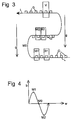
- FIG. 3 shows an example of a manufacturing system, on which the output signals of an acceleration sensor as part of a large-scale production of sensor units can be calibrated fully automatically according to the invention.
- This Example shows five, each with its own robot Jobs B1, M1, M2, B2, V on these jobs spatially partly side by side, partly one above the other are arranged, cf. the direction g shown in Figure 3 gravity.
- All housing parts G shown each contain a sensor unit S, E / T, cf. the example shown in Figures 1 and 2 a sensor unit, with all housing parts G in series are attached one behind the other on a tape L.
- These sensor units each contain an acceleration sensor S, which output signals b, cf. the figure 1, corresponding to the current acceleration / deceleration of this acceleration sensor delivers.
- the sensor units also each contain an electronic unit E / T, which is used to evaluate the output signals b and for the delivery of acceleration signals, see. serve the output terminal C of the electronics unit E.
- the sensor units S shown each contain in turn a seismic mass, which is symbolically shown in FIG a ball K, which is attached to a resilient lever arm, is shown. - As a rule, however, the seismic Mass K has a different shape and a different attachment to the acceleration sensor S own.
- the tape L runs in an S-shape from bottom right to top left over the five jobs.
- the direction g of gravity is of great importance in the invention, because they are used to calibrate the sensor units S, E / T is used by the output signals b of the acceleration sensors S, cf. the figure 1, in two tilted against each other Positions of the acceleration sensor S, cf. the Positions at the two measuring stations shown in FIG. 3 M1 and M2, measured and these measurement results then together be compared.
- the first measurements are found at the next workstation M1 the sensor units S, E / T instead, while the relevant Sensor unit through the manufacturing plant in a first horizontal Position is held in which the gravitation g pulls the seismic mass K down. It is about contact fingers a measuring robot the connections shown in Figure 1 M operating voltages are supplied, whereby such Connections M directly or indirectly through gravity + 1g triggered output signals b of the acceleration sensor concerned S can be measured, cf. the figure 2. the first measured values measured in this way are - in the figures not shown - memory of an electronic measuring circuit, which is common to the two measuring robots M1, M2.
- the tape L goes up an arc, whereby the same sensor unit S, E / T finally tilted by 180 ° on second measuring station M2 passes.
- the manufacturing plant stops thus the sensor unit S, E / T during the second measurement M2 of the output signal b in a second position opposite the first position is tilted so that gravity g the seismic mass K in the opposite direction which pulls from the direction of gravity given at the first measuring point M1 clearly differentiates.
- the force + 1g acted on the first measuring station M1, and on second measuring station -1g to the seismic mass K so that the Difference of the output signals b of the force 2g on the seismic Mass K corresponds to twice the acceleration due to gravity G.
- the second measuring station M2 assigned measurement robot again those shown in FIG Connections M operating voltages supplied and via such Connections M directly or indirectly through gravity -1g triggered output signals b of the acceleration sensor in question S measured.
- the measuring circuit connected to the measuring station M2 is compared those in the first and the second measurement M1, M2 output signals measured at this acceleration sensor S. b.
- the result of this comparison or a derived one Value represents a calibration value that has the influence describes the gravity g on the output signal b.
- the electronic unit E / T - and / or the acceleration sensor S - according to this Calibration value by applying electrical pulses - e.g. via the electrical connections A - Adjusted so that the electronics unit E / T later the output signals b Convert to calibrated acceleration signals can - the calibrated acceleration signals occur then at port C.
- the voltage divider according to the result of the comparison is subsequently adjusted so that the electronics unit E / T later calibrated the output signals b in Acceleration signals C can convert.
- the voltage divider can also be from a series connection of MOS-FET channels, the control voltage adjusted on these FETs by means of the supplied voltage pulses can be - also e.g. by interrupting Semiconductor routes or by converting Zener diodes into Shorts.
- Each voltage pulse used for adjustment according to the invention E.g. by a machine in the manufacturing plant or more connections of the electronics unit E / T or indirectly by means of the machine inside the electronics unit E / T can be generated. That only needs one very little effort, which is particularly important for large series production is cheap.
- a particularly high one Adjustment accuracy can be achieved with very little effort if, as was shown by way of example with reference to FIG. 3, the Sensor unit between the first measurement M1 and the second Measurement M2 is tilted by approximately 180 °, the sensor unit in their two positions during measurements M1, M2 is held so that the seismic mass of the acceleration sensor under the influence of gravity moved as much as possible. Then the difference is the measured Maximum output signals: it corresponds to the influence twice the gravitational acceleration 2g on the seismic Dimensions. Furthermore, the measuring accuracy of the sensor unit extraordinary big:
- Figure 4 illustrates the influence of the change in Tilt angle w of the acceleration sensor S to the output signal b of this acceleration sensor S.
- the acceleration sensor S on the first Measuring station M1 or, tilted by 180 °, at the second measuring station M2 then its seismic mass K is at most one and deflected in the other opposite direction and the output signal b is particularly large at both measuring stations, - At these two measuring stations, as shown in FIG. 4, an inadvertently small change in the tilt angle w in each case very little influence on the level of the output signal b has.
- the optimal spatial arrangement of the measuring stations M1, M2 depends therefore based on the direction of oscillation of the seismic mass K. onto the surface of the tape L.
- the one shown in FIG Example mainly concerns acceleration sensors S, in which the seismic mass K corresponds to FIG. 3 perpendicular to the bottom of the housing part G and thus perpendicular can swing to band L. Then it is optimal if the measurements M1, M2 is carried out at places where the tape L runs horizontally as in FIG.
- the seismic mass K within the sensor unit S, E / T only at an angle or perpendicular to that belt surface can swing on which the sensor unit S, E / T is attached then it is much better to use the measuring stations M1, M2 to be arranged spatially so that the tape L is not horizontal on them, but rather obliquely or vertically - the cheapest it is when the seismic at both measuring points M1, M2 Mass can swing towards the center of the earth. It is therefore favorable if the seismic mass K at the second measuring station M2 pulled in one direction by gravity g which is opposite to the direction at the first measuring station M1 is.
- the adjusted sensor units finally against environmental influences to protect, after the second measurement M2 - and after the final manufacture of all necessary inside the housing electrical connections at B2 - the sensor unit, see. the workplace v, hermetically sealed / encapsulated be finally separated from the tape L before this sensor unit becomes.
- the sensor units produced by the method according to the invention allow, evenly for all sensor units, regardless of the original bad tolerance their sensitivity, especially the tight tolerance of the sensor units to reach. This is primarily achieved by the output signal of the acceleration sensor at two different positions of the sensor with respect to the earth's gravitational field is measured, and by using the sensor unit Voltage pulses is adjusted subsequently.
- the acceleration sensor S together with the Electronics unit E / T form a monolithic body.
- your electronic unit E / T can also be a control unit included or connected to a control unit, which at least one of the operating voltages between circuit points of the electronic unit E / T to a predeterminable value stabilized.
Landscapes
- Physics & Mathematics (AREA)
- General Physics & Mathematics (AREA)
- Pressure Sensors (AREA)
- Manipulator (AREA)
- Measuring Fluid Pressure (AREA)
- Indication And Recording Devices For Special Purposes And Tariff Metering Devices (AREA)
- Investigating Or Analysing Materials By Optical Means (AREA)
- Testing Or Calibration Of Command Recording Devices (AREA)
Description
- Fig 1
- eine Sensoreinheit in der Draufsicht,
- Fig 2
- dieselbe Sensoreinheit in einer Seitenansicht,
- Fig 3
- ein Schema für eine Fertigungsanlage zur Durchführung des erfindungsgemäßen Verfahrens mit einem S-förmig bewegtem Band, und
- Fig 4
- ein Diagramm zur Veranschaulichung der erreichbaren Justiergenauigkeit, abhängig von der Stellung der Sensoreinheit bei den zwei Meßplätzen.
Claims (13)
- Verfahren zur Herstellung einer kalibrierten Sensoreinheit (S, E/T) im Rahmen einer Serienfertigung mittels einer automatisierten Fertigungsanlage, wobei die Sensoreinheit (S, E/T) einen eine seismische Masse (K) aufweisenden Beschleunigungssensor (S) und eine zur Auswertung der Ausgangssignale (b) des Beschleunigungssensors (S) und zur Lieferung von Beschleunigungssignalen (C) dienende Elektronikeinheit (E/T) enthält,
dadurch gekennzeichnet,daß die Sensoreinheit (S, E/T) während einer ersten Messung (M1) des Ausgangssignals (b) durch die Fertigungsanlage in einer ersten Stellung gehalten wird, bei der die Gravitation (g) die seismische Masse (K) in eine erste Richtung zieht,daß die Sensoreinheit danach während einer zweiten Messung (M2) des Ausgangssignales (b) durch die Fertigungsanlage in einer zweiten Stellung gehalten wird, die gegenüber der ersten Stellung so gekippt ist, daß die Gravitation (g) die seismische Masse (K) in eine zweite Richtung zieht, die sich von der ersten Richtung deutlich unterscheidet,daß anschließend die bei beiden Messungen (M1, M2) gemessenen Ausgangssignale (b) verglichen werden, wobei aus dem Ergebnis des Vergleichs ein Kalibrierwert abgeleitet wird, der den Einfluß der Gravitation (g) auf das Ausgangssignal (b) beschreibt, unddaß schließlich die Elektronikeinheit (E/T) entsprechend dem Kalibrierwert durch Anlegen von elektrischen Impulsen so justiert (Z) wird, daß die Elektronikeinheit (E/T) später die Ausgangssignale (b) in kalibrierte Beschleunigungssignale (C) umwandeln kann. - Verfahren nach Patentanspruch 1,
dadurch gekennzeichnet,daß die Elektronikeinheit (E/T) mindestens einen Spannungs teiler enthält, wobei der Spannungsteiler entsprechend dem Ergebnis des Vergleichs (über A) so justiert wird, daß die Elektronikeinheit (E/T) später die Ausgangssignale (b) in kalibrierte Beschleunigungssignale (C) umwandeln kann. - Verfahren nach Patentanspruch 2,
dadurch gekennzeichnet,daß der Spannungsteiler aus mehreren Teilen besteht, von denen mindestens ein Teil durch Zenerdioden (Z) überbrückt ist, wobei zur Justierung des Spannungsteilers entsprechend dem Kalibrierwert ein Teil dieser Zenerdioden (Z) durch einen Spannungsimpuls (über A) in einen Kurzschluß umgewandelt wird. - Verfahren nach Patentanspruch 2,
dadurch gekennzeichnet,daß der Spannungsteiler aus mehreren Teilen besteht, von denen mindestens ein Teil durch niederohmige Halbleiterstrecken überbrückt ist, wobei zur Justierung des Spannungsteilers entsprechend dem Kalibrierwert ein Teil dieser Halbleiterstrecken durch einen Spannungsimpuls (über A) unterbrochen wird. - Verfahren nach Patentanspruch 3 oder 4,
dadurch gekennzeichnet,daß der Spannungsimpuls durch einen Automaten der Fertigungsanlage (über A) der Elektronikeinheit (E/T) zugeleitet oder durch den Automaten in der Elektronikeinheit (E/T) erzeugt wird. - Verfahren nach einem der vorhergehenden Patentansprüche,
dadurch gekennzeichnet,daß für die Messungen (M1, M2) Spannungen über einen mit mindestens einem Kontaktfinger ausgestatteten Roboterarm der Elektronikeinheit (E/T) zugeführt werden, um die Elektronikeinheit (E/T) betriebsfähig zu machen. - Verfahren nach einem der vorhergehenden Patentansprüche,
dadurch gekennzeichnet,daß die Fertigungsanlage ein Band (L) bewegt, daß mehrere Sensoreinheiten (S, E/T; G) in Reihe hintereinander auf dem Band (L) so befestigt sind, daß sie beim Fortbewegen des Bandes (L) nacheinander in einer ersten Stellung an einem ersten Meßplatz (M1) der Fertigungsanlage zur automatischen ersten Messung vorbeilaufen, unddaß das Band (L) danach einen Bogen nach oben oder unten durchläuft, so daß die Sensoreinheiten (S, E/T; G) in einer zweiten, gegenüber der ersten Stellung gekippten Stellung an einem zweiten Meßplatz (M2) zur automatischen zweiten Messung vorbeilaufen. - Verfahren nach Patentanspruch 7,
dadurch gekennzeichnet,daß das Band so geführt wird, daß die Richtung der ersten Stellung gegenüber der Richtung der zweiten Stellung um angenähert 180° gedreht ist, so daß sich die seismische Masse (K) des Beschleunigungssensors (S) unter dem Einfluß der Gravitation (g) möglichst stark bewegt und der Vergleich der Ergebnisse der beiden Messungen dem Einfluß der doppelten Erdbeschleunigung (2g) auf die seismische Masse (K) entspricht. - Verfahren nach Patentanspruch 7 oder 8,
dadurch gekennzeichnet,daß, bevor die erste Messung (M1) durchgeführt wird, nur die für die Messung notwendigen elektrischen Anschlüsse (P) von Elektronikeinheit (E/T) und Beschleunigungssensor (S) (bei B1) miteinander verbunden werden. - Verfahren nach einem der Patentansprüche 7 bis 9,
dadurch gekennzeichnet,daß die Sensoreinheiten (S, E/T) auf einem Leadframe angebracht sind, welches auf dein Band (L) befestigt ist, und daß nach der zweiten Messung (M2, bei B2) die übrigen elektrischen Anschlüsse zwischen Beschleunigungssensor (S), Elektronikeinheit (E/T) und Teilen des Leadframe miteinander verbunden werden. - Verfahren nach einem der Patentansprüche 7 bis 10,
dadurch gekennzeichnet,daß nach der zweiten Messung (M2) die Sensoreinheit (S, E/T; G) zum Schutz gegen äußere Einflüsse (bei V) luftdicht verschlossen wird, bevor sie vom Band (L) getrennt wird. - Sensoreinheit, hergestellt nach einem der vorhergehenden Patentansprüche,
dadurch gekennzeichnet,daß der Beschleunigungssensor (S) zusammen mit der Elektronikeinheit (E/T) einen monolithischen Körper bildet. - Sensoreinheit nach Patentanspruch 12,
dadurch gekennzeichnet,daß ihre Elektronikeinheit (E/T) eine Regeleinheit enthält oder mit einer Regeleinheit verbunden ist, welche zumindest eine der Betriebsspannungen zwischen Schaltungspunkten der Elektronikeinheit (E/T) auf einen vorgebbaren Wert stabilisiert.
Applications Claiming Priority (3)
| Application Number | Priority Date | Filing Date | Title |
|---|---|---|---|
| DE4404265 | 1994-02-10 | ||
| DE4404265A DE4404265C3 (de) | 1994-02-10 | 1994-02-10 | Verfahren zur Herstellung einer kalibrierten Sensoreinheit |
| PCT/DE1995/000162 WO1995022063A1 (de) | 1994-02-10 | 1995-02-07 | Verfahren zur herstellung einer kalibrierten sensoreinheit |
Publications (3)
| Publication Number | Publication Date |
|---|---|
| EP0744031A1 EP0744031A1 (de) | 1996-11-27 |
| EP0744031B1 true EP0744031B1 (de) | 2000-06-14 |
| EP0744031B2 EP0744031B2 (de) | 2003-07-09 |
Family
ID=6509976
Family Applications (1)
| Application Number | Title | Priority Date | Filing Date |
|---|---|---|---|
| EP95907561A Expired - Lifetime EP0744031B2 (de) | 1994-02-10 | 1995-02-07 | Verfahren zur herstellung einer kalibrierten sensoreinheit |
Country Status (6)
| Country | Link |
|---|---|
| EP (1) | EP0744031B2 (de) |
| JP (1) | JP2780064B2 (de) |
| AT (1) | ATE193947T1 (de) |
| DE (1) | DE4404265C3 (de) |
| NO (1) | NO963343L (de) |
| WO (1) | WO1995022063A1 (de) |
Families Citing this family (9)
| Publication number | Priority date | Publication date | Assignee | Title |
|---|---|---|---|---|
| DE19851409C2 (de) * | 1998-11-07 | 2001-08-02 | Deutsch Zentr Luft & Raumfahrt | Verfahren zur Bestimmung des Nullpunktfehlers eines Akzelerometers |
| DE10041736C1 (de) * | 2000-08-25 | 2002-02-28 | Brose Fahrzeugteile | Vorrichtung und Verfahren zum Erfassen mindestens einer Kenngröße einer Bewegung von zueinander beweglichen Teilen, insbesondere für Verstellantriebe in Kraftfahrzeugen |
| DE20018538U1 (de) * | 2000-10-27 | 2002-03-07 | Mannesmann Vdo Ag | Sensormodul |
| DE10164108A1 (de) * | 2001-12-24 | 2003-07-03 | Wabco Gmbh & Co Ohg | Verfahren für die Funktionsprüfung eines Querbeschleunigungssensors |
| JP2004268717A (ja) * | 2003-03-07 | 2004-09-30 | Calsonic Kansei Corp | ロールオーバ検出器試験装置 |
| EP2469286A1 (de) * | 2010-12-22 | 2012-06-27 | Gemalto SA | Verfahren zur Kalibrierung des Beschleunigungsmesser einer gesicherten Elementvorrichtung |
| DE102014202026A1 (de) * | 2014-02-05 | 2015-08-06 | Robert Bosch Gmbh | Verfahren und Vorrichtung zum Kalibrieren eines Beschleunigungssensors in einem Kraftfahrzeug |
| CN109229045B (zh) * | 2018-09-27 | 2019-10-01 | 广州亚美信息科技有限公司 | 一种基于车联网终端的翻车检测方法及系统 |
| EP3654041B1 (de) * | 2018-11-16 | 2022-10-19 | Siemens Industry Software NV | Volumenbeschleunigungssensorkalibrierung |
Family Cites Families (10)
| Publication number | Priority date | Publication date | Assignee | Title |
|---|---|---|---|---|
| DE664553C (de) * | 1936-01-25 | 1938-08-29 | Askania Werke A G Vormals Cent | Vorrichtung zum Eichen von Beschleunigungs- und Schwingungsmessern |
| CA1085645A (en) * | 1978-07-06 | 1980-09-16 | Henry O. Baker | Portable accelerometer |
| DE3844351A1 (de) * | 1988-12-30 | 1990-07-05 | Bosch Gmbh Robert | Elektronische einrichtung |
| DE3921560A1 (de) * | 1989-06-30 | 1991-01-10 | Deutsche Forsch Luft Raumfahrt | Verfahren und vorrichtung zum hochgenauen ermitteln von beschleunigungen |
| DE3922977A1 (de) * | 1989-07-12 | 1991-01-24 | Texas Instruments Deutschland | Trimmschaltung und unter verwendung einer solchen trimmschaltung ausfuehrbares abgleichverfahren |
| JP2582160B2 (ja) * | 1989-07-20 | 1997-02-19 | 株式会社日立製作所 | センサ装置 |
| DE4033885A1 (de) * | 1990-10-25 | 1992-04-30 | Bosch Gmbh Robert | Beschleunigungssensor |
| DE4108081A1 (de) * | 1991-03-13 | 1992-09-17 | Bosch Gmbh Robert | Verfahren zum abgleich eines laengsbeschleunigungs-sensors fuer kraftfahrzeuge |
| DE4205868A1 (de) * | 1992-02-26 | 1993-09-02 | Teldix Gmbh | Verfahren und einrichtung zum kalibrieren einer messeinrichtung |
| DE4229068C2 (de) * | 1992-09-01 | 1994-06-16 | Bosch Gmbh Robert | Beschleunigungsschalter und Verfahren zur Herstellung |
-
1994
- 1994-02-10 DE DE4404265A patent/DE4404265C3/de not_active Expired - Lifetime
-
1995
- 1995-02-07 WO PCT/DE1995/000162 patent/WO1995022063A1/de not_active Ceased
- 1995-02-07 JP JP7520904A patent/JP2780064B2/ja not_active Expired - Lifetime
- 1995-02-07 EP EP95907561A patent/EP0744031B2/de not_active Expired - Lifetime
- 1995-02-07 AT AT95907561T patent/ATE193947T1/de not_active IP Right Cessation
-
1996
- 1996-08-09 NO NO963343A patent/NO963343L/no not_active Application Discontinuation
Also Published As
| Publication number | Publication date |
|---|---|
| EP0744031A1 (de) | 1996-11-27 |
| NO963343L (no) | 1996-08-12 |
| DE4404265C2 (de) | 1995-12-21 |
| JP2780064B2 (ja) | 1998-07-23 |
| EP0744031B2 (de) | 2003-07-09 |
| DE4404265C3 (de) | 2001-02-15 |
| NO963343D0 (no) | 1996-08-09 |
| DE4404265A1 (de) | 1995-08-17 |
| WO1995022063A1 (de) | 1995-08-17 |
| JPH09503306A (ja) | 1997-03-31 |
| ATE193947T1 (de) | 2000-06-15 |
Similar Documents
| Publication | Publication Date | Title |
|---|---|---|
| DE69018285T2 (de) | Kraft-Messfühler mit Widerstandselementen. | |
| EP0772046B1 (de) | Magnetfeldsensor und Strom- oder Energiesensor | |
| DE19744050C2 (de) | Magnetischer Sensor | |
| DE19906067B4 (de) | Halbleitersensor für physikalische Größen und Verfahren zu dessen Herstellung | |
| DE69309392T2 (de) | Sensor für eine richtungsabhängige physikalische Grösse | |
| DE102004014708B4 (de) | Halbleitersensor für eine dynamische Grösse | |
| EP0744031B2 (de) | Verfahren zur herstellung einer kalibrierten sensoreinheit | |
| DE4446890A1 (de) | Kapazitiver Beschleunigungssensor und Verfahren zu dessen Herstellung | |
| DE10054964B4 (de) | Beschleunigungssensor mit einem Beschleunigungsdetektorchip in dem Durchgangsloch eines Signalverarbeitungschips auf einem Montageträger | |
| DE19635280A1 (de) | Drosselventilöffnungssensor | |
| DE10049356A1 (de) | Halbleitersensor | |
| DE102004042761B4 (de) | Sensoranordnung eines Kapazitätstyps für eine dynamische Grösse | |
| DE19651269A1 (de) | Halbleiterbeschleunigungssensor | |
| DE20018538U1 (de) | Sensormodul | |
| DE4341890C2 (de) | Magnetische Detektionseinrichtung | |
| DE19903585B4 (de) | Halbleitersensor und Halbleitersensorchip und Halbleitersensorgehäuse | |
| DE112020002469T5 (de) | Gaspedal-Vorrichtung | |
| EP1746426B1 (de) | Stromsensor | |
| DE69528572T2 (de) | Messwertaufnehmer für Beschleunigungszustand | |
| EP3764054B1 (de) | Sensoranordnung zum erfassen einer auslenkung einer drahtelektrode | |
| DE2435958C3 (de) | Geschwindigkeits-Messwandler | |
| DE4341662C2 (de) | Beschleunigungssensor | |
| DE102020207355A1 (de) | Sensorvorrichtung | |
| DE8816606U1 (de) | Elektronische Einrichtung | |
| DE102019213127A1 (de) | Vorrichtung für einen nichtkontaktiven sensor mit esd-schutzstruktur |
Legal Events
| Date | Code | Title | Description |
|---|---|---|---|
| PUAI | Public reference made under article 153(3) epc to a published international application that has entered the european phase |
Free format text: ORIGINAL CODE: 0009012 |
|
| 17P | Request for examination filed |
Effective date: 19960520 |
|
| AK | Designated contracting states |
Kind code of ref document: A1 Designated state(s): AT FR IT |
|
| GRAG | Despatch of communication of intention to grant |
Free format text: ORIGINAL CODE: EPIDOS AGRA |
|
| 17Q | First examination report despatched |
Effective date: 19990820 |
|
| GRAG | Despatch of communication of intention to grant |
Free format text: ORIGINAL CODE: EPIDOS AGRA |
|
| GRAH | Despatch of communication of intention to grant a patent |
Free format text: ORIGINAL CODE: EPIDOS IGRA |
|
| GRAH | Despatch of communication of intention to grant a patent |
Free format text: ORIGINAL CODE: EPIDOS IGRA |
|
| GRAA | (expected) grant |
Free format text: ORIGINAL CODE: 0009210 |
|
| AK | Designated contracting states |
Kind code of ref document: B1 Designated state(s): AT FR IT |
|
| REF | Corresponds to: |
Ref document number: 193947 Country of ref document: AT Date of ref document: 20000615 Kind code of ref document: T |
|
| ITF | It: translation for a ep patent filed | ||
| ET | Fr: translation filed | ||
| PLBI | Opposition filed |
Free format text: ORIGINAL CODE: 0009260 |
|
| 26 | Opposition filed |
Opponent name: ROBERT BOSCH GMBH Effective date: 20010111 |
|
| PLBF | Reply of patent proprietor to notice(s) of opposition |
Free format text: ORIGINAL CODE: EPIDOS OBSO |
|
| PLBF | Reply of patent proprietor to notice(s) of opposition |
Free format text: ORIGINAL CODE: EPIDOS OBSO |
|
| PLAW | Interlocutory decision in opposition |
Free format text: ORIGINAL CODE: EPIDOS IDOP |
|
| PLAW | Interlocutory decision in opposition |
Free format text: ORIGINAL CODE: EPIDOS IDOP |
|
| PUAH | Patent maintained in amended form |
Free format text: ORIGINAL CODE: 0009272 |
|
| STAA | Information on the status of an ep patent application or granted ep patent |
Free format text: STATUS: PATENT MAINTAINED AS AMENDED |
|
| 27A | Patent maintained in amended form |
Effective date: 20030709 |
|
| AK | Designated contracting states |
Designated state(s): AT FR IT |
|
| ET3 | Fr: translation filed ** decision concerning opposition | ||
| PGFP | Annual fee paid to national office [announced via postgrant information from national office to epo] |
Ref country code: AT Payment date: 20100212 Year of fee payment: 16 |
|
| REG | Reference to a national code |
Ref country code: FR Ref legal event code: TP |
|
| PG25 | Lapsed in a contracting state [announced via postgrant information from national office to epo] |
Ref country code: AT Free format text: LAPSE BECAUSE OF NON-PAYMENT OF DUE FEES Effective date: 20110207 |
|
| PGFP | Annual fee paid to national office [announced via postgrant information from national office to epo] |
Ref country code: FR Payment date: 20120227 Year of fee payment: 18 |
|
| PGFP | Annual fee paid to national office [announced via postgrant information from national office to epo] |
Ref country code: IT Payment date: 20120224 Year of fee payment: 18 |
|
| REG | Reference to a national code |
Ref country code: FR Ref legal event code: ST Effective date: 20131031 |
|
| PG25 | Lapsed in a contracting state [announced via postgrant information from national office to epo] |
Ref country code: IT Free format text: LAPSE BECAUSE OF NON-PAYMENT OF DUE FEES Effective date: 20130207 |
|
| PG25 | Lapsed in a contracting state [announced via postgrant information from national office to epo] |
Ref country code: FR Free format text: LAPSE BECAUSE OF NON-PAYMENT OF DUE FEES Effective date: 20130228 |