EP0741248B1 - Fluidisches Steuerelement - Google Patents
Fluidisches Steuerelement Download PDFInfo
- Publication number
- EP0741248B1 EP0741248B1 EP96106192A EP96106192A EP0741248B1 EP 0741248 B1 EP0741248 B1 EP 0741248B1 EP 96106192 A EP96106192 A EP 96106192A EP 96106192 A EP96106192 A EP 96106192A EP 0741248 B1 EP0741248 B1 EP 0741248B1
- Authority
- EP
- European Patent Office
- Prior art keywords
- housing
- control element
- lever
- arm
- control
- Prior art date
- Legal status (The legal status is an assumption and is not a legal conclusion. Google has not performed a legal analysis and makes no representation as to the accuracy of the status listed.)
- Expired - Lifetime
Links
Images


Classifications
-
- F—MECHANICAL ENGINEERING; LIGHTING; HEATING; WEAPONS; BLASTING
- F16—ENGINEERING ELEMENTS AND UNITS; GENERAL MEASURES FOR PRODUCING AND MAINTAINING EFFECTIVE FUNCTIONING OF MACHINES OR INSTALLATIONS; THERMAL INSULATION IN GENERAL
- F16K—VALVES; TAPS; COCKS; ACTUATING-FLOATS; DEVICES FOR VENTING OR AERATING
- F16K31/00—Actuating devices; Operating means; Releasing devices
- F16K31/02—Actuating devices; Operating means; Releasing devices electric; magnetic
- F16K31/06—Actuating devices; Operating means; Releasing devices electric; magnetic using a magnet, e.g. diaphragm valves, cutting off by means of a liquid
- F16K31/0682—Actuating devices; Operating means; Releasing devices electric; magnetic using a magnet, e.g. diaphragm valves, cutting off by means of a liquid with an articulated or pivot armature
-
- F—MECHANICAL ENGINEERING; LIGHTING; HEATING; WEAPONS; BLASTING
- F16—ENGINEERING ELEMENTS AND UNITS; GENERAL MEASURES FOR PRODUCING AND MAINTAINING EFFECTIVE FUNCTIONING OF MACHINES OR INSTALLATIONS; THERMAL INSULATION IN GENERAL
- F16K—VALVES; TAPS; COCKS; ACTUATING-FLOATS; DEVICES FOR VENTING OR AERATING
- F16K31/00—Actuating devices; Operating means; Releasing devices
- F16K31/02—Actuating devices; Operating means; Releasing devices electric; magnetic
- F16K31/06—Actuating devices; Operating means; Releasing devices electric; magnetic using a magnet, e.g. diaphragm valves, cutting off by means of a liquid
- F16K31/08—Actuating devices; Operating means; Releasing devices electric; magnetic using a magnet, e.g. diaphragm valves, cutting off by means of a liquid using a permanent magnet
- F16K31/082—Actuating devices; Operating means; Releasing devices electric; magnetic using a magnet, e.g. diaphragm valves, cutting off by means of a liquid using a permanent magnet using a electromagnet and a permanent magnet
-
- Y—GENERAL TAGGING OF NEW TECHNOLOGICAL DEVELOPMENTS; GENERAL TAGGING OF CROSS-SECTIONAL TECHNOLOGIES SPANNING OVER SEVERAL SECTIONS OF THE IPC; TECHNICAL SUBJECTS COVERED BY FORMER USPC CROSS-REFERENCE ART COLLECTIONS [XRACs] AND DIGESTS
- Y10—TECHNICAL SUBJECTS COVERED BY FORMER USPC
- Y10T—TECHNICAL SUBJECTS COVERED BY FORMER US CLASSIFICATION
- Y10T137/00—Fluid handling
- Y10T137/8593—Systems
- Y10T137/86493—Multi-way valve unit
- Y10T137/86847—Pivoted valve unit
Definitions
- the invention relates to a fluidic control element a housing, a control chamber formed in the housing, open into the at least two flow channels, at least one in the control room and one of the flow channels assigned sealing seat and a protruding into the control room, tongue surrounded with elastic material, the between a closed position in which they fit the seal covers, as well as an open position in which it fits the seal releases, is mobile, the tongue being an arm of one forms a two-armed lever that swivels in one Clamped casing, tightly enclosing the lever is stored from the elastic material and its second arm protrudes from the control room as an actuating arm.
- a fluidic control element is in the US 4,765,370.
- From DE-PS 12 47 793 is also a fluidic control element known in which the protruding into the control room Tongue rigid with the hinged armature of an electromagnetic drive connected is.
- the solenoid actuator is from the control room separated by a membrane with a pocket for Recording of the tongue is provided.
- the tongue is between two opposite valve seats that moved she alternately releases and closes.
- the on their peripheral edge clamped membrane has a funnel-shaped Transition area to the pocket where the tongue is, to provide little resistance to their deflection. In this transition area, however, the membrane is not supported and therefore cannot withstand high pressure differences. In addition, it is highly stressed as it takes turns is stretched and compressed.
- the object of the invention is a fluidic control element to create its tongue as part of a two-armed lever can be moved regardless of the pressure in the control room and whose mobility does not depend on the pressure in the control room.
- the invention provides a fluidic control element for Provided the sealing of the control room only a little towards the drive side due to the movement of the tongue is deformed and high pressure differences between the control room and drive side withstands. Because the pivot axis of the two-armed Lever at the interface between the control room and The drive side is the deflection of the lever in this Area very small. The deformation is correspondingly low the elastic covering, which also acts as a seal and serves as a bearing element.
- the bearing of the two-armed lever with one across it Longitudinally arranged bearing arm stands out both characterized by great flexibility, so that the driving forces can be kept low, as well as by an accurate Definition of the pivot axis so that a wobble movement of the Tongue despite its storage in resilient material is largely avoided.
- the casing good support in the area of the swivel joints, because it is clamped between the housing parts. As Swivel joint and at the same time serving as a seal therefore also keeps very high pressure differences between the control room and drive side stood.
- the two-armed lever with one transverse to its longitudinal direction arranged bearing arm provided.
- This type of storage is characterized by both great flexibility, so that the driving forces can be kept low as well through a precise definition of the swivel axis so that a Tumbling of the tongue despite its storage in elastic compliant material is largely avoided.
- the ends accommodated in the swivel joints advantageously have a rectangular cross-sectional profile.
- a Round cross-sectional profile has the disadvantage that the corresponding ends are glued into the swivel joints must not in the swivel joint during a swiveling movement slide.
- Ends with a rectangular cross-sectional profile on the other hand, only press the ends into the corresponding ones Openings in the swivel joints.
- the housing is made of two flat, at least approximately the same, along one Parting level joined housing parts that are simple and can be produced inexpensively.
- the control is there only three parts: two identical housing parts and the combined control / sealing element, which is simply between the two housing parts is placed, which are then joined together be tense.
- the driving forces required to operate the tongue are in a further advantageous embodiment significantly reduced by fluidic feedback.
- This feedback is achieved in that the lever between its pivot joints and the actuating arm a section has, in a pressure chamber formed in the housing is included; this pressure space is through in two the envelope of the lever sealed against each other pressure chambers divided; each assigned to a sealing seat Flow channels are with the one on the same side Pressure chamber connected.
- the one facing the respective pressure chamber Surface of the lever section is thus by a Pressurized, which strives to put the tongue against the press on the sealing seat located on the same side.
- Corresponding the number to be applied to the actuating arm is lower Driving forces.
- the fluidic control element has a generally cuboid shape Housing 10, which consists of two almost identical housing parts 10a, 10b is composed. Between the housing parts 10a, 10b, a control room 12 is formed. In the control room 12 two opposing sealing seats 14 protrude into it, one of which on the housing part 10a and the other is formed symmetrically on the housing part 10b. From every sealing seat 14 starts a flow channel 16 which is angled through the wall of the relevant housing part 10a, 10b is guided and opens on a narrow side of the housing 10.
- Another flow channel 15 leads out of the control chamber 12 through the wall of the housing part 10a and opens at the same Narrow side of the case.
- the two housing parts 10a, 10b differ from one another only by the flow channel 15, which is formed only in the housing part 10a.
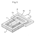
- Control / sealing element clamped which is shown separately in Fig. 5 is shown. It consists of a rigid rectangular Frame 20, on one, longer side of an operating arm 22 is connected and the opposite side carries a control arm 24, and from a sealing frame 26 Elastomeric material that encloses the control arm 24 and a side 20a of the frame 20 forms.
- This combined Control / sealing element forms a two-armed lever, the first arm by the control arm 24 and the second Arm formed by the frame 20 and the actuating arm 22 is, the side 20a of the frame 20 is a bearing arm forms, which is transverse to the longitudinal direction of the two-armed lever is arranged. The outer ends of this bearing arm protrude the sealing frame 26 out.
- Shorter sides of the frame 20 form with the longer one Page 20b and the actuating arm 22 a fork-shaped Lever section.
- the rectangular sealing frame 26 surrounds the covering of the control arm 24 at a distance and thus forms an outer boundary and sealing of the control room 12.
- the bearing arm 20a is, as shown in Fig. 4, on the outer edge its wrapping between the housing parts 10a, 10b clamped.
- the covering made of elastomer material forms two swivel joints attached to opposite housing walls for the ends of the bearing arm 20a and thus pivot bearings for consisting of control arm 24, frame 20 and actuating arm 22 two-armed lever.
- the control arm 24 with its covering made of elastomer material forms a tongue 30, which is movable between the sealing seats 14, as in FIG. 1 can be seen, and releases the one sealing seat during it covers the other.
- the actuation of the tongue 30 takes place by means of the housing 10 on a narrow side outstanding actuating arm 22.
- the fluidic control element described can be used to shut off Forwarding, throttling, switching, mixing or distributing of fluid flows can be used.
- the one at the Actuating arm 22 opposite narrow side of the housing 10 opening flow channels 15, 16 preferably form one standardized fluidic interface to the other System elements coupled with appropriate interfaces can be.
- the actuating arm 22 is different Drive units coupled, which are also preferred standardized and therefore interchangeable. Several Embodiments of such drive units are by way of example shown in Figures 7 to 12.
- a bistable solenoid valve is created after the arrangement Fig. 9 by a connected to the actuating arm 22 Permanent magnet 60, which is in front of the poles of an electromagnet 62 is movable, which has two windings 64, 66.
- a current pulse through the winding 66 brings the Actuating arm 22 in the position shown in Fig. 9, which in currentless state obtained by the permanent magnet 60 remains; a current pulse through winding 64 overcomes the Holding force of the permanent magnet 60 and switches the operating lever 22 in the opposite position, which in currentless state obtained by the permanent magnet 60 remains.
- Such a bistable solenoid valve is also called Pulse valve called.
- FIG. 10 shows an embodiment of a drive unit, which is characterized by a particularly low drive power distinguished.
- actuating arm 22 that is one end of an elongated piezoelectric flexure 70 coupled, the opposite end of a frame 72 is firmly clamped.
- the flexure 70 consists of two layers, each with a connecting line is created.
- the piezoelectric flexure 70 acts electrically as a capacitor. When applying a voltage a low charge or discharge current flows only briefly, that quickly goes back to zero. The control is therefore extremely low performance. Under the effect of the saved The bending element 70 is deflected and takes the load Actuating lever 22 with.
- the fluidic control element described can also be used as a proportional valve operate.
- the electromagnet fed with a variable current.
- the through a spring loaded in an end position anchor 50 is so deflected more, the larger the flowing in the electromagnet Electricity is.
- This arrangement can also be used as an analog electro-pneumatic Transducers are called.
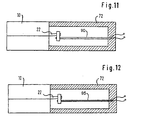
- the actuating arm 22 can also, as shown in FIG. 11, by one or more shape memory elements 90 be relocated.
- a shape memory element 90 ensures that after a deflection of the actuating arm 22 after heating of the element 90 this again exactly in its original position returns.
- a coupling of a bimetallic drive 95 possible with the actuating arm 22, wherein the bimetallic drive 95, for example, with a corresponding one Power source can be connected to one side of the bimetal drive 95 heats accordingly to the actuating arm 22 deflect.
- Control element is between the housing parts 10a, 10b a pressure chamber 32 formed by a between the arm 20a and actuating arm 22 located lever portion 34 in two pressure chambers 32a, 32b is divided.
- the lever section 34 like control arm 24, is completely encased surrounded by elastomer material. This wrapping is at the same time the seal of the pressure chamber 32 and that of Pressure chambers 32a, 32b against each other.
- the flow channels 16 are through the wall of the housing parts 10a, 10b through sections 16a into the pressure chamber 32a or 32b extended.
- the lever section 34 is thus by the differential pressure acted upon between the pressure chambers 32a, 32b. Since it is on the operating side of the two-armed lever is located, the differential pressure in the pressure chamber 32 a force that supports the actuating force:
- the Switching system is fed back. Through this execution can the pressure forces occurring at the sealing seats 14 be at least partially compensated.
- the housing parts 10a, 10b can be made of almost any Material inexpensively and in large quantities become. In particular, they can be molded from plastic.
- the combined control / sealing element can be made from one stamped part are produced, some with an elastomer material is encapsulated, at the same time the sealing frame is molded on becomes.
- the control element is assembled very simple, as only two housing parts with the interposition of the combined control / sealing element along one Partition plane are to be joined together.
Landscapes
- Engineering & Computer Science (AREA)
- General Engineering & Computer Science (AREA)
- Mechanical Engineering (AREA)
- Physics & Mathematics (AREA)
- Electromagnetism (AREA)
- Multiple-Way Valves (AREA)
- Servomotors (AREA)
- Fluid-Driven Valves (AREA)
Description
- Fig. 1
- einen Schnitt einer ersten Ausführungsform des fluidischen Steuerelements entlang der Linie I-I in Fig. 2;
- Fig. 2
- einen Schnitt dieses Steuerelements entlang Linie II-II in Fig. 1;
- Fig. 3
- einen Schnitt des Steuerelements entlang Linie III-III in Fig. 2;
- Fig. 4
- einen Schnitt des Steuerelements entlang Linie IV-IV in Fig. 2;
- Fig. 5
- eine Perspektivansicht eines kombinierten Steuer-Dichtelements für die in den Figuren 1 bis 4 gezeigte Ausführungsform;
- Fig. 6
- eine Schnittansicht analog der Fig. 1, jedoch bei einer bevorzugten Ausführungsform des Steuerelements; und
- Fig. 7 bis 12
- schematisch verschiedene Ausführungen von Antrieben, mit denen das Steuerelement gekoppelt werden kann.
Claims (13)
- Fluidisches Steuerelement mit einem Gehäuse (10), einem in dem Gehäuse (10) gebildeten Steuerraum (12), in den wenigstens zwei Strömungskanäle (16) münden, wenigstens einem im Steuerraum (12) angeordneten und einem der Strömungskanäle zugeordneten Dichtsitz (14) und einer in den Steuerraum (12) hineinragenden, mit elastischem Material umgebenen Zunge (30), die zwischen einer Schließstellung, in der sie den Dichtsitz (14) abdeckt, sowie einer Öffnungsstellung, in der sie den Dichtsitz (14) freigibt, beweglich ist, wobei die Zunge (30) einen Arm eines zweiarmigen Hebels bildet, der schwenkbar in einer im Gehäuse (10) eingespannten, den Hebel eng umschließenden Umhüllung aus dem elastischen Material gelagert ist und dessen zweiter Arm als Betätigungsarm (22) aus dem Steuerraum (12) herausragt, dadurch gekennzeichnet, daß zur Lagerung des Hebels zwei Lager vorgesehen sind, die als quer zur Längsrichtung des Hebels in entgegengesetzten Gehäusewänden gegenüberliegend angeordnete Drehgelenke ausgebildet sind, wobei der Hebel einen quer zu seiner Längsrichtung angeordneten Lagerarm (20a) aufweist, dessen äußere, gleichfalls von der Umhüllung eng umschlossenen Enden in den durch ihre Umhüllung gebildeten Drehgelenken im Gehäuse gelagert sind.
- Steuerelement nach Anspruch 1, dadurch gekennzeichnet, daß die Drehgelenke jeweils zwischen zwei Teilen (10a, 10b) des Gehäuses eingespannt sind.
- Steuerelement nach Anspruch 1 oder 2, dadurch gekennzeichnet, daß die in den Drehgelenken aufgenommenen Enden ein rechteckiges Querschnittsprofil haben.
- Steuerelement nach einem der vorstehenden Ansprüche, dadurch gekennzeichnet, daß die aus der Umhüllung seitlich herausragenden Enden des Lagerarms (20a) durch einen gabelförmigen Hebelabschnitt (20) starr mit dem Betätigungsarm (22) verbunden sind.
- Steuerelement nach einem der vorstehenden Ansprüche, dadurch gekennzeichnet, daß die Umhüllung einteilig mit einem den Steuerraum (12) umschließenden Dichtrahmen (26) aus demselben elastischen Material ausgebildet und der Dichtrahmen (26) zwischen den zwei Teilen (10a, 10b) des Gehäuses (10) eingespannt ist.
- Steuerelement nach einem der vorstehenden Ansprüche, dadurch gekennzeichnet, daß das Gehäuse (10) aus zwei flachen, entlang einer Trennebene aneinandergefügten Gehäuseteilen (10a, 10b) besteht.
- Steuerelement nach Anspruch 6, dadurch gekennzeichnet, daß die Gehäuseteile (10a, 10b) zumindest annähernd gleich ausgebildet sind.
- Steuerelement nach einem der vorstehenden Ansprüche, dadurch gekennzeichnet, daß zwei Dichtsitze (14) in dem Steuerraum einander gegenüberliegend an je einem Gehäuseteil (10a, 10b) angeordnet sind.
- Stuerelement nach einem der vorstehenden Ansprüche, dadurch gekennzeichnet, daß der Hebel zwischen seinem Schwenklager und dem Betätigungsarm (22) einen Abschnitt (34) aufweist, der in einem im Gehäuse gebildeten Druckraum (32) eingeschlossen ist, daß dieser Druckraum (32) in zwei durch die Umhüllung des Hebels gegeneinander abgedichtete Druckkammern (32a, 32b) geteilt ist und daß wenigstens eine der Druckkammern mit einem der Strömungskanäle (16) verbunden ist.
- Steuerelement nach den Ansprüchen 8 und 9, dadurch gekennzeichnet, daß die den Dichtsitzen (14) zugeordneten Strömungskanäle (16) jeweils mit der auf derselben Seite gelegenen Druckkammer (32a, 32b) verbunden sind.
- Steuerelement nach einem der vorstehenden Ansrpüche, dadurch gekennzeichnet, daß die Umhüllung durch eine Umspritzung aus Elastomermaterial gebildet ist.
- Steuerelement nach einem der vorstehenden Ansprüche, dadurch gekennzeichnet, daß das Gehäuse (10) allgemein quaderförmig ausgebildet ist und die Strömungskanäle (16) durch die Gehäusewandungen zu einer Schmalseite des Gehäuses geführt sind.
- Steuerelement nach einem der vorstehenden Ansprüche, dadurch gekennzeichnet, daß der Betätigungsarm (22) wahlweise ankoppelbar ist anein Handbetätigungselement (40),einen Elektromagnet,ein Antriebsteil eines Impuls-Elektromagnetantriebs,ein piezoelektrisches Antriebselement,einen Proportionalantrieb,einen fluidischen Antrieb (80) mit Kolben und/oder Membran,einen Bimetallantrieb (95),einen Antrieb mit Formgedächtniselementen (90).
Applications Claiming Priority (2)
| Application Number | Priority Date | Filing Date | Title |
|---|---|---|---|
| DE29507380U DE29507380U1 (de) | 1995-05-03 | 1995-05-03 | Fluidisches Steuerelement |
| DE29507380U | 1995-05-03 |
Publications (3)
| Publication Number | Publication Date |
|---|---|
| EP0741248A2 EP0741248A2 (de) | 1996-11-06 |
| EP0741248A3 EP0741248A3 (de) | 1998-07-01 |
| EP0741248B1 true EP0741248B1 (de) | 2001-12-19 |
Family
ID=8007578
Family Applications (1)
| Application Number | Title | Priority Date | Filing Date |
|---|---|---|---|
| EP96106192A Expired - Lifetime EP0741248B1 (de) | 1995-05-03 | 1996-04-19 | Fluidisches Steuerelement |
Country Status (4)
| Country | Link |
|---|---|
| US (1) | US5711346A (de) |
| EP (1) | EP0741248B1 (de) |
| JP (1) | JP3746326B2 (de) |
| DE (2) | DE29507380U1 (de) |
Cited By (2)
| Publication number | Priority date | Publication date | Assignee | Title |
|---|---|---|---|---|
| EP2365239A1 (de) | 2010-03-12 | 2011-09-14 | Asco Numatics GmbH | Vorrichtung zur Durchflussregelung eines flüssigen oder gasförmigen Mediums |
| CN103375612A (zh) * | 2012-04-20 | 2013-10-30 | 比尔克特韦尔克有限公司 | 流体控制元件 |
Families Citing this family (25)
| Publication number | Priority date | Publication date | Assignee | Title |
|---|---|---|---|---|
| JP2000517037A (ja) * | 1997-06-09 | 2000-12-19 | ビルケルト ベルケ ゲーエムベーハー ウント ツエーオー. | 小型電磁弁 |
| DE29722085U1 (de) * | 1997-12-13 | 1998-02-26 | Festo Ag & Co | Ventil |
| US6174136B1 (en) | 1998-10-13 | 2001-01-16 | Liquid Metronics Incorporated | Pump control and method of operating same |
| US6280147B1 (en) | 1998-10-13 | 2001-08-28 | Liquid Metronics Incorporated | Apparatus for adjusting the stroke length of a pump element |
| DE29822958U1 (de) * | 1998-12-23 | 1999-04-22 | Buerkert Werke Gmbh & Co | Baugruppe zur Ansteuerung von Stellgliedern |
| DE29822959U1 (de) * | 1998-12-23 | 1999-05-12 | Buerkert Werke Gmbh & Co | Steuerelement für Fluid |
| DE29901855U1 (de) | 1999-02-03 | 1999-04-08 | Buerkert Werke Gmbh & Co | Fluidisches Steuerelement |
| US6264432B1 (en) | 1999-09-01 | 2001-07-24 | Liquid Metronics Incorporated | Method and apparatus for controlling a pump |
| ATE284490T1 (de) | 2000-05-25 | 2004-12-15 | Festo Ag & Co | Ventileinrichtung |
| GB0016505D0 (en) * | 2000-07-06 | 2000-08-23 | Wygnanski Wladyslaw | Improved electro-magnetic device |
| DE10134935B4 (de) * | 2001-07-18 | 2004-08-12 | Heatec Thermotechnik Gmbh | Gasventil für Kleinverbraucher |
| DE20119401U1 (de) * | 2001-11-29 | 2002-04-11 | Buerkert Werke Gmbh & Co | Miniaturisiertes Magnetventil |
| US6981518B2 (en) * | 2002-03-15 | 2006-01-03 | Cytonome, Inc. | Latching micro-regulator |
| DE502004000792D1 (de) * | 2003-04-07 | 2006-08-03 | Buerkert Werke Gmbh & Co Kg | Ventil mit piezoelektrischem Antrieb |
| DE102004021765A1 (de) * | 2004-04-30 | 2005-11-24 | Günter Biechele | Klappenventil |
| DE102004046977A1 (de) * | 2004-09-28 | 2006-04-06 | Festo Ag & Co. | Aktoreinrichtung |
| DE202006006825U1 (de) † | 2006-04-27 | 2007-08-30 | Bürkert Werke GmbH & Co. KG | Ventil mit einem elektromagnetischen Antrieb |
| DE102007004377A1 (de) * | 2007-01-29 | 2008-08-07 | Diener Precision Pumps Ltd. | Elektromagnetisch zu betätigendes Ventil |
| EP2068056B1 (de) * | 2007-12-08 | 2010-08-04 | Asco Joucomatic GmbH | Vorrichtung zur Durchflussregelung eines flüssigen oder gasförmigen Mediums |
| DE102010051743B4 (de) | 2010-11-19 | 2022-09-01 | C. Miethke Gmbh & Co. Kg | Programmierbares Hydrocephalusventil |
| DE202013003049U1 (de) * | 2013-04-03 | 2013-05-06 | Bürkert Werke GmbH | Magnetventil, Batterie aus Magnetventilen sowie Werkzeug |
| WO2017063707A1 (de) * | 2015-10-15 | 2017-04-20 | Festo Ag & Co. Kg | Ventileinrichtung |
| DE102017131246A1 (de) * | 2017-12-22 | 2019-06-27 | Bürkert Werke GmbH & Co. KG | Ventil mit elektrodynamischen Aktor |
| EP3597937B1 (de) * | 2018-07-20 | 2022-12-28 | Hamilton Sundstrand Corporation | Servoventil |
| DE102018220321B4 (de) * | 2018-11-27 | 2021-09-23 | Festo Se & Co. Kg | Ventilanordnung |
Family Cites Families (11)
| Publication number | Priority date | Publication date | Assignee | Title |
|---|---|---|---|---|
| DE1037225B (de) * | 1955-01-15 | 1958-08-21 | Produktionsmaterial Ab | Ventil |
| US2876553A (en) * | 1956-11-07 | 1959-03-10 | Dearborn Gage Company | Air gage head |
| DE1247793B (de) * | 1964-04-23 | 1967-08-17 | Nostorag A G | Magnetventil |
| US3385309A (en) * | 1965-11-03 | 1968-05-28 | Philco Ford Corp | Fluid flow control means |
| DE1268921B (de) * | 1965-12-30 | 1968-05-22 | Zd Y Pruumyslove Automatizace | Steuerglied der Duesensteuerung bei hydraulischen Regelschiebern |
| GB1525235A (en) * | 1974-11-21 | 1978-09-20 | Lucas Industries Ltd | Servo pressure operated actuator arrangements |
| JPS608223Y2 (ja) * | 1979-08-31 | 1985-03-22 | 黒田精工株式会社 | 電磁弁の手動切換装置 |
| US4333390A (en) * | 1980-02-29 | 1982-06-08 | The Bendix Corporation | Balanced pivoted vane valve |
| DE3503357A1 (de) * | 1985-02-01 | 1986-08-07 | Westfälische Metall Industrie KG Hueck & Co, 4780 Lippstadt | Doppelsitzventil |
| US4765370A (en) * | 1985-11-29 | 1988-08-23 | Fujikura Rubber Ltd. | Directional control valve |
| DE3739048C2 (de) * | 1987-11-17 | 2001-08-09 | Buerkert Gmbh | Mehrwegeventil |
-
1995
- 1995-05-03 DE DE29507380U patent/DE29507380U1/de not_active Expired - Lifetime
-
1996
- 1996-04-19 EP EP96106192A patent/EP0741248B1/de not_active Expired - Lifetime
- 1996-04-19 DE DE59608475T patent/DE59608475D1/de not_active Expired - Lifetime
- 1996-04-26 JP JP14058396A patent/JP3746326B2/ja not_active Expired - Fee Related
- 1996-04-30 US US08/640,311 patent/US5711346A/en not_active Expired - Lifetime
Cited By (4)
| Publication number | Priority date | Publication date | Assignee | Title |
|---|---|---|---|---|
| EP2365239A1 (de) | 2010-03-12 | 2011-09-14 | Asco Numatics GmbH | Vorrichtung zur Durchflussregelung eines flüssigen oder gasförmigen Mediums |
| EP2365239B1 (de) * | 2010-03-12 | 2015-03-04 | Asco Numatics GmbH | Vorrichtung zur Durchflussregelung eines flüssigen oder gasförmigen Mediums |
| CN103375612A (zh) * | 2012-04-20 | 2013-10-30 | 比尔克特韦尔克有限公司 | 流体控制元件 |
| US9115820B2 (en) | 2012-04-20 | 2015-08-25 | Buerkert Werke Gmbh | Fluidic control element with rounded shaft |
Also Published As
| Publication number | Publication date |
|---|---|
| JPH08338406A (ja) | 1996-12-24 |
| US5711346A (en) | 1998-01-27 |
| DE59608475D1 (de) | 2002-01-31 |
| JP3746326B2 (ja) | 2006-02-15 |
| EP0741248A3 (de) | 1998-07-01 |
| DE29507380U1 (de) | 1995-08-24 |
| EP0741248A2 (de) | 1996-11-06 |
Similar Documents
| Publication | Publication Date | Title |
|---|---|---|
| EP0741248B1 (de) | Fluidisches Steuerelement | |
| EP1158182B1 (de) | Ventileinrichtung | |
| EP0914563B1 (de) | Piezoelektrisch betätigtes mikroventil | |
| DE3334159C2 (de) | ||
| DE3739048C2 (de) | Mehrwegeventil | |
| EP0914564B1 (de) | Piezoelektrisch betätigtes mikroventil | |
| EP1026407B1 (de) | Fluidisches Steuerelement | |
| DE4405657A1 (de) | Magnetventil | |
| EP0884511B1 (de) | Miniaturisierte Ventileinrichtung | |
| EP1959178B1 (de) | Elektromagnetisch zu betätigendes Ventil | |
| DE4135993C2 (de) | Magnetventil in Baukastenbauweise | |
| DE19947848A1 (de) | Aktuator zur Betätigung eines Stellgliedes, insbesondere eines Gaswechselventils mit einseitiger Federanordnung | |
| DE3608550A1 (de) | Piezo-elektrisch betaetigbares ventil | |
| EP1899634B1 (de) | Ventilvorrichtung | |
| EP2336619B1 (de) | Ventil mit einem Betätigungsglied | |
| EP1582793A1 (de) | Elektropneumatisches Ventil | |
| DE2826538C2 (de) | ||
| DE3619818A1 (de) | Magnetventilsystem | |
| DE2540751C2 (de) | ||
| DE102006001142B3 (de) | Längsschieberventil, insbesondere für die Verwendung von transkritischen CO2 (R 744) Klimakreisläufe | |
| DE102011011578B4 (de) | Magnetventil | |
| WO2008141690A2 (de) | Pumpe | |
| EP1477715B1 (de) | Klappankerventil | |
| DE202006006862U1 (de) | Ventilvorrichtung | |
| DE102016204956B4 (de) | Membranventil |
Legal Events
| Date | Code | Title | Description |
|---|---|---|---|
| PUAI | Public reference made under article 153(3) epc to a published international application that has entered the european phase |
Free format text: ORIGINAL CODE: 0009012 |
|
| AK | Designated contracting states |
Kind code of ref document: A2 Designated state(s): DE FR GB |
|
| PUAL | Search report despatched |
Free format text: ORIGINAL CODE: 0009013 |
|
| AK | Designated contracting states |
Kind code of ref document: A3 Designated state(s): DE FR GB |
|
| 17P | Request for examination filed |
Effective date: 19980724 |
|
| 17Q | First examination report despatched |
Effective date: 20000320 |
|
| GRAG | Despatch of communication of intention to grant |
Free format text: ORIGINAL CODE: EPIDOS AGRA |
|
| GRAG | Despatch of communication of intention to grant |
Free format text: ORIGINAL CODE: EPIDOS AGRA |
|
| GRAH | Despatch of communication of intention to grant a patent |
Free format text: ORIGINAL CODE: EPIDOS IGRA |
|
| GRAH | Despatch of communication of intention to grant a patent |
Free format text: ORIGINAL CODE: EPIDOS IGRA |
|
| GRAA | (expected) grant |
Free format text: ORIGINAL CODE: 0009210 |
|
| AK | Designated contracting states |
Kind code of ref document: B1 Designated state(s): DE FR GB |
|
| REG | Reference to a national code |
Ref country code: GB Ref legal event code: IF02 |
|
| REF | Corresponds to: |
Ref document number: 59608475 Country of ref document: DE Date of ref document: 20020131 |
|
| GBT | Gb: translation of ep patent filed (gb section 77(6)(a)/1977) |
Effective date: 20020301 |
|
| ET | Fr: translation filed | ||
| PLBE | No opposition filed within time limit |
Free format text: ORIGINAL CODE: 0009261 |
|
| STAA | Information on the status of an ep patent application or granted ep patent |
Free format text: STATUS: NO OPPOSITION FILED WITHIN TIME LIMIT |
|
| 26N | No opposition filed | ||
| REG | Reference to a national code |
Ref country code: GB Ref legal event code: 732E Free format text: REGISTERED BETWEEN 20100422 AND 20100428 |
|
| REG | Reference to a national code |
Ref country code: FR Ref legal event code: TP Ref country code: FR Ref legal event code: CJ Ref country code: FR Ref legal event code: CD |
|
| PGFP | Annual fee paid to national office [announced via postgrant information from national office to epo] |
Ref country code: GB Payment date: 20110421 Year of fee payment: 16 |
|
| GBPC | Gb: european patent ceased through non-payment of renewal fee |
Effective date: 20120419 |
|
| PG25 | Lapsed in a contracting state [announced via postgrant information from national office to epo] |
Ref country code: GB Free format text: LAPSE BECAUSE OF NON-PAYMENT OF DUE FEES Effective date: 20120419 |
|
| PGFP | Annual fee paid to national office [announced via postgrant information from national office to epo] |
Ref country code: FR Payment date: 20130515 Year of fee payment: 18 |
|
| REG | Reference to a national code |
Ref country code: FR Ref legal event code: ST Effective date: 20141231 |
|
| PG25 | Lapsed in a contracting state [announced via postgrant information from national office to epo] |
Ref country code: FR Free format text: LAPSE BECAUSE OF NON-PAYMENT OF DUE FEES Effective date: 20140430 |
|
| PGFP | Annual fee paid to national office [announced via postgrant information from national office to epo] |
Ref country code: DE Payment date: 20150415 Year of fee payment: 20 |
|
| REG | Reference to a national code |
Ref country code: DE Ref legal event code: R071 Ref document number: 59608475 Country of ref document: DE |