EP0741248B1 - Fluidic control element - Google Patents
Fluidic control element Download PDFInfo
- Publication number
- EP0741248B1 EP0741248B1 EP96106192A EP96106192A EP0741248B1 EP 0741248 B1 EP0741248 B1 EP 0741248B1 EP 96106192 A EP96106192 A EP 96106192A EP 96106192 A EP96106192 A EP 96106192A EP 0741248 B1 EP0741248 B1 EP 0741248B1
- Authority
- EP
- European Patent Office
- Prior art keywords
- housing
- control element
- lever
- arm
- control
- Prior art date
- Legal status (The legal status is an assumption and is not a legal conclusion. Google has not performed a legal analysis and makes no representation as to the accuracy of the status listed.)
- Expired - Lifetime
Links
Images


Classifications
-
- F—MECHANICAL ENGINEERING; LIGHTING; HEATING; WEAPONS; BLASTING
- F16—ENGINEERING ELEMENTS AND UNITS; GENERAL MEASURES FOR PRODUCING AND MAINTAINING EFFECTIVE FUNCTIONING OF MACHINES OR INSTALLATIONS; THERMAL INSULATION IN GENERAL
- F16K—VALVES; TAPS; COCKS; ACTUATING-FLOATS; DEVICES FOR VENTING OR AERATING
- F16K31/00—Actuating devices; Operating means; Releasing devices
- F16K31/02—Actuating devices; Operating means; Releasing devices electric; magnetic
- F16K31/06—Actuating devices; Operating means; Releasing devices electric; magnetic using a magnet, e.g. diaphragm valves, cutting off by means of a liquid
- F16K31/0682—Actuating devices; Operating means; Releasing devices electric; magnetic using a magnet, e.g. diaphragm valves, cutting off by means of a liquid with an articulated or pivot armature
-
- F—MECHANICAL ENGINEERING; LIGHTING; HEATING; WEAPONS; BLASTING
- F16—ENGINEERING ELEMENTS AND UNITS; GENERAL MEASURES FOR PRODUCING AND MAINTAINING EFFECTIVE FUNCTIONING OF MACHINES OR INSTALLATIONS; THERMAL INSULATION IN GENERAL
- F16K—VALVES; TAPS; COCKS; ACTUATING-FLOATS; DEVICES FOR VENTING OR AERATING
- F16K31/00—Actuating devices; Operating means; Releasing devices
- F16K31/02—Actuating devices; Operating means; Releasing devices electric; magnetic
- F16K31/06—Actuating devices; Operating means; Releasing devices electric; magnetic using a magnet, e.g. diaphragm valves, cutting off by means of a liquid
- F16K31/08—Actuating devices; Operating means; Releasing devices electric; magnetic using a magnet, e.g. diaphragm valves, cutting off by means of a liquid using a permanent magnet
- F16K31/082—Actuating devices; Operating means; Releasing devices electric; magnetic using a magnet, e.g. diaphragm valves, cutting off by means of a liquid using a permanent magnet using a electromagnet and a permanent magnet
-
- Y—GENERAL TAGGING OF NEW TECHNOLOGICAL DEVELOPMENTS; GENERAL TAGGING OF CROSS-SECTIONAL TECHNOLOGIES SPANNING OVER SEVERAL SECTIONS OF THE IPC; TECHNICAL SUBJECTS COVERED BY FORMER USPC CROSS-REFERENCE ART COLLECTIONS [XRACs] AND DIGESTS
- Y10—TECHNICAL SUBJECTS COVERED BY FORMER USPC
- Y10T—TECHNICAL SUBJECTS COVERED BY FORMER US CLASSIFICATION
- Y10T137/00—Fluid handling
- Y10T137/8593—Systems
- Y10T137/86493—Multi-way valve unit
- Y10T137/86847—Pivoted valve unit
Landscapes
- Engineering & Computer Science (AREA)
- General Engineering & Computer Science (AREA)
- Mechanical Engineering (AREA)
- Physics & Mathematics (AREA)
- Electromagnetism (AREA)
- Multiple-Way Valves (AREA)
- Servomotors (AREA)
- Fluid-Driven Valves (AREA)
Description
Die Erfindung betrifft ein fluidisches Steuerelement mit einem Gehäuse, einem in dem Gehäuse gebildeten Steuerraum, in den wenigstens zwei Strömungskanäle münden, wenigstens einem im Steuerraum angeordneten und einem der Strömungskanäle zugeordneten Dichtsitz und einer in den Steuerraum hineinragenden, mit elastischem Material umgebenen Zunge, die zwischen einer Schließstellung, in der sie den Dichtsitz abdeckt, sowie einer Öffnungsstellung, in der sie den Dichtsitz freigibt, geweglich ist, wobei die Zunge einen Arm eines zweiarmigen Hebels bildet, der schwenkbar in einer im Gehäuse eingespannten, den Hebel eng umschließenden Umhüllung aus dem elastischen Material gelagert ist und dessen zweiter Arm als Betätigungsarm aus dem Steuerraum herausragt. Ein solches fluidisches Steuerelement ist in der US 4 765 370 gezeigt.The invention relates to a fluidic control element a housing, a control chamber formed in the housing, open into the at least two flow channels, at least one in the control room and one of the flow channels assigned sealing seat and a protruding into the control room, tongue surrounded with elastic material, the between a closed position in which they fit the seal covers, as well as an open position in which it fits the seal releases, is mobile, the tongue being an arm of one forms a two-armed lever that swivels in one Clamped casing, tightly enclosing the lever is stored from the elastic material and its second arm protrudes from the control room as an actuating arm. Such a fluidic control element is in the US 4,765,370.
Ähnliche fluidische Steuerelemente sind bereits aus der DE-AS 10 37 225 und der DE 25 30 362 C2 bekannt. Den aus diesen beiden Druckschriften bekannten Steuerelementen ist gemeinsam, daß die Zunge durch zwei Kippgelenke, die durch das die Zunge umgebende elastische Material gebildet sind, am Gehäuse befestigt ist. Nachteilig an den bekannten Steuerelementen ist, daß ein hoher Druck im Steuerraum die Stellung der Zunge ungewünscht beeinflussen kann. Damit ist auch die Beweglichkeit der Zunge und der von den Lagern entgegengebrachte Widerstand zur Verstellung der Zunge abhängig vom Druck im Steuerraum. Zusätzlich hat der auf diejenigen Seiten der Lager einwirkende Druck einen Einfluß auf die Beweglichkeit der Zunge und den Verstellwiderstand, die nicht zum Steuerraum angrenzen.Similar fluidic control elements are already from DE-AS 10 37 225 and DE 25 30 362 C2 known. The one from these common controls known in both publications, that the tongue through two tilt joints, through which the Tongue surrounding elastic material are formed on the housing is attached. A disadvantage of the known controls is that a high pressure in the control room changes the position of the Tongue can undesirably affect. So there is mobility the tongue and the one from the bearings Resistance to tongue adjustment depending on Pressure in the control room. In addition, he has on those sides the bearing pressure has an influence on the mobility the tongue and the adjustment resistance, which is not for Adjacent control room.
Aus der DE-PS 12 47 793 ist ferner ein fluidisches Steuerelement bekannt, bei dem die in den Steuerraum hineinragende Zunge starr mit dem Klappanker eines Elektromagnetantriebs verbunden ist. Der Elektromagnetantrieb ist von dem Steuerraum durch eine Membran getrennt, die mit einer Tasche zur Aufnahme der Zunge versehen ist. Die Zunge wird zwischen zwei einander gegenüberliegenden Ventilsitzen bewegt, die sie abwechselnd freigibt und verschließt. Die an ihrem Umfangsrand eingespannte Membran weist einen trichterförmigen Übergangsbereich zu der Tasche auf, in der die Zunge steckt, um deren Auslenkung nur wenig Widerstand entgegenzusetzen. In diesem Übergangsbereich ist die Membran jedoch nicht abgestützt und kann daher keinen hohen Druckdifferenzen standhalten. Überdies wird sie hoch beansprucht, da sie abwechselnd gedehnt und gestaucht wird.From DE-PS 12 47 793 is also a fluidic control element known in which the protruding into the control room Tongue rigid with the hinged armature of an electromagnetic drive connected is. The solenoid actuator is from the control room separated by a membrane with a pocket for Recording of the tongue is provided. The tongue is between two opposite valve seats that moved she alternately releases and closes. The on their peripheral edge clamped membrane has a funnel-shaped Transition area to the pocket where the tongue is, to provide little resistance to their deflection. In this transition area, however, the membrane is not supported and therefore cannot withstand high pressure differences. In addition, it is highly stressed as it takes turns is stretched and compressed.
Aufgabe der Erfindung ist es, ein fluidisches Steuerelement zu schaffen, dessen Zunge als Teil eines zweiarmigen Hebels unabhängig vom Druck im Steuerraum bewegt werden kann und dessen Beweglichkeit nicht vom Druck im Steuerraum abhängt.The object of the invention is a fluidic control element to create its tongue as part of a two-armed lever can be moved regardless of the pressure in the control room and whose mobility does not depend on the pressure in the control room.
Diese Aufgabe wird bei einem Steuerelement der eingangs angegebenen Art dadurch gelöst, daß zur Lagerung des Hebels zwei Lager vorgesehen sind, die als quer zur Längsrichtung des Hebels in entgegengesetzten Gehäusewänden gegenüberliegend angeordnete Drehgelenke ausgebildet sind, wobei der Hebel einen quer zu seiner Längsrichtung angeordneten Lagerarm aufweist, dessen äußere, gleichsfalls von der Umhüllung eng umschlossenen Enden in den durch ihre Umhüllung gebildeten Drehgelenken im Gehäuse gelagert sind. Durch diesen völlig aymmetrischen Aufbau einerseits und durch die Verwendung von Drehgelenken andererseits kommt es zu keiner Verlagerung der Zunge bei höheren Drücken im Steuerraum. Die auf die Drehgelenke einwirkenden axialen Kräfte heben sich dadurch gegenseitig auf. Ein weiterer Vorteil bei Verwendung von DRehgelenken besteht darin, daß diese üblichlerweise eine längere Lebensdauer als die sehr stark auf Zug belasteten Kippgelenke besitzen. In deren stark auf Zug belasteten Bereichen können sehr schnell Risse im elastischen Material auftreten, die später zu Undichtigkeiten führen können.This task is specified for a control element of the type mentioned at the beginning Art solved in that for the storage of the lever two bearings are provided which are considered transverse to the longitudinal direction opposite the lever in opposite housing walls arranged swivel joints are formed, the Lever a bearing arm arranged transversely to its longitudinal direction has, the outer, also from the casing tightly enclosed ends in the formed by their wrapping Swivel joints are stored in the housing. Through this completely asymmetrical structure on the one hand and through the use on the other hand, there is no displacement of swivel joints the tongue at higher pressures in the control room. The on the Axial forces acting on swivel joints are thereby lifted each other. Another advantage of using DRange joints is that they are usually a longer life than the very heavily loaded on train Have tilt joints. In their areas that are heavily exposed to train can very quickly crack in the elastic material occur that can later lead to leaks.
Durch die Erfindung wird ein fluidisches Steuerelement zur Verfügung gestellt, bei dem die Abdichtung des Steuerraums zur Antriebsseite hin durch die Bewegung der Zunge nur wenig verformt wird und hohen Druckdifferenzen zwischen Steuerraum und Antriebsseite standhält. Da die Schenkachse des zweiarmigen Hebels an der Schnittstelle zwischen Steuerraum und Antriebsseite liegt, ist die Auslenkung des Hebels in diesem Bereich sehr klein. Entsprechend gering ist die Verformung der elastischen Umhüllung, die zugleich als Abdichtung und als Lagerelement dient.The invention provides a fluidic control element for Provided the sealing of the control room only a little towards the drive side due to the movement of the tongue is deformed and high pressure differences between the control room and drive side withstands. Because the pivot axis of the two-armed Lever at the interface between the control room and The drive side is the deflection of the lever in this Area very small. The deformation is correspondingly low the elastic covering, which also acts as a seal and serves as a bearing element.
Die Lagerung des zweiarmigen Hebels mit einem quer zu seiner Längsrichtung angeordneten Lagerarm zeichnet sich sowohl durch große Nachgiebigkeit aus, so daß die Antriebskräfte geringgehalten werden können, als auch durch eine genaue Definition der Schwenkachse, so daß eine Taumelbewegung der Zunge trotz ihrer Lagerung in elastisch nachgiebigem Material weitgehend vermieden wird.The bearing of the two-armed lever with one across it Longitudinally arranged bearing arm stands out both characterized by great flexibility, so that the driving forces can be kept low, as well as by an accurate Definition of the pivot axis so that a wobble movement of the Tongue despite its storage in resilient material is largely avoided.
Gemäß einer bevorzugten Ausführungsform verfügt die Umhüllung im Bereich der Drehgelenke über eine gute Abstützung, da sie zwischen den Gehäuseteilen eingespannt ist. Die als Drehgelenk und zugleich als Abdichtung fungierende Umhüllung hält daher auch sehr hohen Druckdifferenzen zwischen Steuerraum und Antriebsseite stand. According to a preferred embodiment, the casing good support in the area of the swivel joints, because it is clamped between the housing parts. As Swivel joint and at the same time serving as a seal therefore also keeps very high pressure differences between the control room and drive side stood.
Bei der erfindungsgemäßen Aubildung des Steuerelements ist der zweiarmige Hebel mit einem quer zu seiner Längsrichtung angeordneten Lagerarm versehen. Diese Art der Lagerung zeichnet sich sowohl durch große Nachgiebigkeit aus, so daß die Antriebskräfte geringgehalten werden können, als auch durch eine genaue Definition der Schwenkachse, so daß eine Taumelbewegung der Zunge trotz ihrer Lagerung in elastisch nachgiebigem Material weitgehend vermieden wird.In the formation of the control element according to the invention the two-armed lever with one transverse to its longitudinal direction arranged bearing arm provided. This type of storage is characterized by both great flexibility, so that the driving forces can be kept low as well through a precise definition of the swivel axis so that a Tumbling of the tongue despite its storage in elastic compliant material is largely avoided.
Die in den Drehgelenken aufgenommenen Enden haben vorteilhafterweise ein rechteckiges Querschnittsprofil. Bei einem runden Querschnittsprofil besteht der Nachteil, daß die entsprechenden Enden in die Drehgelenke eingeklebt werden müssen, um bei einer Schwenkbewegung nicht im Drehgelenk zu gleiten. Enden mit einem rechteckigen Querschnittsprofil hingegen erfordern nur ein Einpressen der Enden in die entsprechenden Öffnungen in den Drehgelenken.The ends accommodated in the swivel joints advantageously have a rectangular cross-sectional profile. At a Round cross-sectional profile has the disadvantage that the corresponding ends are glued into the swivel joints must not in the swivel joint during a swiveling movement slide. Ends with a rectangular cross-sectional profile on the other hand, only press the ends into the corresponding ones Openings in the swivel joints.
Bei der bevorzugten Ausführungsform besteht das Gehäuse aus zwei flachen, zumindest annähernd gleichen, entlang einer Trennebene aneinandergefügten Gehäuseteilen, die einfach und kostengünstig hergestellt werden können. Ferner wird der zweiarmige Hebel mit Zunge und Betätigungsarm einteilig mit der Umhüllung sowie einem den Steuerraum umschließenden Dichtrahmen ausgebildet, vorzugsweise indem die Umhüllung eine Umspritzung des Hebels aus Elastomermaterial bildet, an die der Dichtrahmen angeformt ist. Das Steuerelement besteht somit lediglich aus drei Teilen: zwei gleichen Gehäuseteilen und dem kombinierten Steuer/Dichtelement, das einfach zwischen die zwei Gehäuseteile gelegt wird, die dann miteinander verspannt werden.In the preferred embodiment, the housing is made of two flat, at least approximately the same, along one Parting level joined housing parts that are simple and can be produced inexpensively. Furthermore, the two-armed lever with tongue and actuating arm in one piece with the wrapping and a surrounding the control room Sealing frame formed, preferably by wrapping forms an encapsulation of the lever from elastomer material which the sealing frame is molded on. The control is there only three parts: two identical housing parts and the combined control / sealing element, which is simply between the two housing parts is placed, which are then joined together be tense.
Die für die Betätigung der Zunge erforderlichen Antriebskräfte werden bei einer weiteren vorteilhaften Ausführungsform durch eine fluidische Rückkopplung erheblich reduziert. Diese Rückkopplung wird dadurch erreicht, daß der Hebel zwischen seinen Drehgelenken und dem Betätigungsarm einen Abschnitt aufweist, der in einem im Gehäuse gebildeten Druckraum eingeschlossen ist; dieser Druckraum ist in zwei durch die Umhüllung des Hebels gegeneinander abgedichtete Druckkammern geteilt; die jeweils einem Dichtsitz zugeordneten Strömungskanäle sind mit der auf derselben Seite gelegenen Druckkammer verbunden. Die der jeweiligen Druckkammer zugewandte Fläche des Hebelabschnitts wird somit durch einen Druck beaufschlagt, der bestrebt ist, die Zunge gegen den auf derselben Seite gelegenen Dichtsitz anzudrücken. Entsprechend geringer sind die am Betätigungsarm aufzubringenden Antriebskräfte. The driving forces required to operate the tongue are in a further advantageous embodiment significantly reduced by fluidic feedback. This feedback is achieved in that the lever between its pivot joints and the actuating arm a section has, in a pressure chamber formed in the housing is included; this pressure space is through in two the envelope of the lever sealed against each other pressure chambers divided; each assigned to a sealing seat Flow channels are with the one on the same side Pressure chamber connected. The one facing the respective pressure chamber Surface of the lever section is thus by a Pressurized, which strives to put the tongue against the press on the sealing seat located on the same side. Corresponding the number to be applied to the actuating arm is lower Driving forces.
Weitere Merkmale und Vorteile der Erfindung ergeben sich aus der folgenden Beschreibung und aus der beigefügten Zeichnung, auf die Bezug genommen wird. In der Zeichnung zeigen:
- Fig. 1
- einen Schnitt einer ersten Ausführungsform des fluidischen Steuerelements entlang der Linie I-I in Fig. 2;
- Fig. 2
- einen Schnitt dieses Steuerelements entlang Linie II-II in Fig. 1;
- Fig. 3
- einen Schnitt des Steuerelements entlang Linie III-III in Fig. 2;
- Fig. 4
- einen Schnitt des Steuerelements entlang Linie IV-IV in Fig. 2;
- Fig. 5
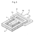
- eine Perspektivansicht eines kombinierten Steuer-Dichtelements
für die in den
Figuren 1 bis 4 gezeigte Ausführungsform; - Fig. 6
- eine Schnittansicht analog der Fig. 1, jedoch bei einer bevorzugten Ausführungsform des Steuerelements; und
- Fig. 7 bis 12
- schematisch verschiedene Ausführungen von Antrieben, mit denen das Steuerelement gekoppelt werden kann.
- Fig. 1
- a section of a first embodiment of the fluidic control element along the line II in Fig. 2;
- Fig. 2
- a section of this control along line II-II in Fig. 1;
- Fig. 3
- a section of the control element along line III-III in Fig. 2;
- Fig. 4
- a section of the control along line IV-IV in Fig. 2;
- Fig. 5
- a perspective view of a combined control sealing element for the embodiment shown in Figures 1 to 4;
- Fig. 6
- a sectional view analogous to Figure 1, but in a preferred embodiment of the control element. and
- 7 to 12
- schematically different versions of drives with which the control element can be coupled.
Das fluidische Steuerelement weist ein allgemein quaderförmiges
Gehäuse 10 auf, das aus zwei nahezu gleichen Gehäuseteilen
10a, 10b zusammengesetzt ist. Zwischen den Gehäuseteilen
10a, 10b ist ein Steuerraum 12 gebildet. In den Steuerraum
12 ragen zwei einander gegenüberliegende Dichtsitze 14 hinein,
von denen der eine am Gehäuseteil 10a und der andere
symmetrisch am Gehäuseteil 10b gebildet ist. Von jedem Dichtsitz
14 geht ein Strömungskanal 16 aus, der abgewinkelt
durch die Wandung des betreffenden Gehäuseteils 10a, 10b
geführt ist und an einer Schmalseite des Gehäuses 10 mündet. The fluidic control element has a generally
Ein weiterer Strömungskanal 15 führt aus dem Steuerraum 12
durch die Wandung des Gehäuseteils 10a und mündet an derselben
Schmalseite des Gehäuses. Die beiden Gehäuseteile 10a,
10b unterscheiden sich voneinander lediglich durch den Strömungskanal
15, der nur in dem Gehäuseteil 10a ausgebildet ist.Another
Zwischen den Gehäuseteilen 10a, 10b ist ein kombiniertes
Steuer/Dichtelement eingespannt, das in Fig. 5 gesondert
dargestellt ist. Es besteht aus einem starren rechteckigen
Rahmen 20, an dessen eine, längere Seite ein Betätigungsarm
22 angeschlossen ist und dessen gegenüberliegende Seite
einen Steuerarm 24 trägt, und aus einem Dichtrahmen 26 aus
Elastomermaterial, der eine Umhüllung des Steuerarms 24
sowie einer Seite 20a des Rahmens 20 bildet. Dieses kombinierte
Steuer/Dichtelement bildet einen zweiarmigen Hebel,
dessen erster Arm durch den Steuerarm 24 und dessen zweiter
Arm durch den Rahmen 20 sowie den Betätigungsarm 22 gebildet
ist, wobei die Seite 20a des Rahmens 20 einen Lagerarm
bildet, der quer zur Längsrichtung des zweiarmigen Hebels
angeordnet ist. Die äußeren Enden dieses Lagerarms ragen aus
dem Dichtrahmen 26 heraus. Die an diese Enden angeschlossenen,
kürzeren Seiten des Rahmens 20 bilden mit der längeren
Seite 20b und dem Betätigungsarm 22 einen gabelförmigen
Hebelabschnitt. Der rechteckförmige Dichtrahmen 26 umgibt
die Umhüllung des Steuerarms 24 mit Abstand und bildet so
eine äußere Begrenzung und Abdichtung des Steuerraumes 12.A combined is between the
Der Lagerarm 20a ist, wie aus Fig. 4 ersichtlich, am Außenrand
seiner Umhüllung zwischen den Gehäuseteilen 10a, 10b
eingespannt. Die Umhüllung aus Elastomermaterial bildet zwei
an gegenüberliegenden Gehäusewänden befestigte Drehgelenke
für die Enden des Lagerarms 20a und somit Schwenklager für
den aus Steuerarm 24, Rahmen 20 und Betätigungsarm 22 bestehenden
zweiarmigen Hebel. Die Enden des Lagerarms 20a haben
ein rechteckiges Querschnittsprofil. Der Steuerarm 24 mit
seiner Umhüllung aus Elastomermaterial bildet eine Zunge 30,
die zwischen den Dichtsitzen 14 beweglich ist, wie aus Fig. 1
ersichtlich, und gibt jeweils den einen Dichtsitz frei, während
sie den anderen abdeckt. Die Betätigung der Zunge 30
erfolgt mittels des aus dem Gehäuse 10 an einer Schmalseite
herausragenden Betätigungsarmes 22.The
Das beschriebene fluidische Steuerelement kann zum Absperren,
Weiterleiten, Drosseln, Umschalten, Mischen oder Verteilen
von Fluidströmen verwendet werden. Die an der dem
Betätigungsarm 22 gegenüberliegenden Schmalseite des Gehäuses
10 mündenden Strömungskanäle 15, 16 bilden vorzugsweise
eine standardisierte fluidische Schnittstelle, an die andere
Systemelemente mit entsprechenden Schnittstellen angekoppelt
werden können. Je nach Verwendungszweck des fluidischen
Steuerelements wird der Betätigungsarm 22 an unterschiedliche
Antriebseinheiten angekoppelt, die ebenfalls vorzugsweise
standardisiert und daher austauschbar sind. Mehrere
Ausführungsformen solcher Antriebseinheiten sind beispielshalber
in den Figuren 7 bis 12 dargestellt.The fluidic control element described can be used to shut off
Forwarding, throttling, switching, mixing or distributing
of fluid flows can be used. The one at the
Bei der Ausführungsform nach Fig. 7 ist eine mechanische
Betätigung mittels eines zweiarmigen, schwenkbar gelagerten
Hebels 40 vorgesehen, der mittels einer Rolle 42 am Ende des
Betätigungsarmes 22 angreift. Diese Anordnung bildet einen
fluidischen Hand- oder Endlagenschalter, kann aber auch als
Weg/Druck-Wandler Verwendung finden. Fakultativ kann der
Hebel 40 oder auch direkt der Betätigungsarm 22 mit einem
fluidischen Antrieb 80 mit einem Kolben und/oder einer
Membran verstellt werden.7 is a mechanical one
Actuation by means of a two-armed, swivel-mounted
Bei der Ausführungsform nach Fig. 8 ist an den Betätigungsarm
22 ein Anker 50 eines Elektromagneten 52 angekoppelt.
Diese Anordnung bildet ein monostabiles Magnetventil.In the embodiment of Fig. 8 is on the
Ein bistabiles Magnetventil entsteht bei der Anordnung nach
Fig. 9 durch einen an den Betätigungsarm 22 angeschlossenen
Permanentmagneten 60, der vor den Polen eines Elektromagneten
62 beweglich ist, welcher zwei Wicklungen 64, 66 aufweist.
Ein Stromimpuls durch die Wicklung 66 bringt den
Betätigungsarm 22 in die in Fig. 9 gezeigte Lage, die im
stromlosen Zustand durch den Permanentmagneten 60 erhalten
bleibt; ein Stromimpuls durch die Wicklung 64 überwindet die
Haltekraft des Permanentmagneten 60 und schaltet den Betätigungshebel
22 in die entgegengesetzte Lage um, die im
stromlosen Zustand durch den Permanentmagneten 60 erhalten
bleibt. Ein solches bistabiles Magnetventil wird auch als
Impulsventil bezeichnet.A bistable solenoid valve is created after the arrangement
Fig. 9 by a connected to the
Schließlich zeigt Fig. 10 eine Ausführungsform einer Antriebseinheit,
die sich durch eine besonders geringe Antriebsleistung
auszeichnet. An den Betätigungsarm 22 ist das
eine Ende eines langgestreckten piezoelektrischen Biegelelementes
70 angekoppelt, dessen entgegengesetztes Ende an
einem Rahmen 72 fest eingespannt ist. Das Biegeelement 70
besteht aus zwei Schichten, an die jeweils eine Anschlußleitung
angelegt ist. Das piezoelektrische Biegeelement 70
wirkt elektrisch als Kondensator. Beim Anlegen einer Spannung
fließt nur kurzzeitig ein geringer Lade- oder Entladestrom,
der schnell auf Null zurückgeht. Die Ansteuerung ist
daher extrem leistungsarm. Unter der Wirkung der gespeicherten
Ladung wird das Biegeelement 70 ausgelenkt und nimmt den
Betätigungshebel 22 mit.10 shows an embodiment of a drive unit,
which is characterized by a particularly low drive power
distinguished. On the
Das beschriebene fluidische Steuerelement kann auch als Proportionalventil
betrieben werden. Für eine solche Verwendung
wird beispielsweise bei der Ausführung nach Fig. 8 der Elektromagnet
mit einem veränderlichen Strom gespeist. Der durch
eine Feder in eine Endlage beaufschlagte Anker 50 wird um so
stärker ausgelenkt, je größer der im Elektromagnet fließende
Strom ist. Diese Anordnung kann auch als analoger elektrischpneumatischer
Wandler bezeichnet werden.The fluidic control element described can also be used as a proportional valve
operate. For such use
8, for example, the electromagnet
fed with a variable current. The through
a spring loaded in an
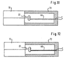
Der Betätigungsarm 22 kann zudem auch, wie in Fig. 11 dargestellt,
durch ein oder mehrere Formgedächtniselemente 90
verlagert werden. Ein Formgedächtniselement 90 sorgt dafür,
daß nach einer Auslenkung des Betätigungsarms 22 nach Erhitzen
des Elements 90 dieser wieder exakt in seine Ursprungsstellung
zurückkehrt. The
Ferner ist eine Koppelung eines Bimetallantriebs 95, wie in
Fig. 12 gezeigt, mit dem Betätigungsarm 22 möglich, wobei
der Bimetallantrieb 95 beispielsweise mit einer entsprechenden
Stromquelle verbunden sein kann, die eine Seite des Bimetallantriebs
95 entsprechend heizt, um den Betätigungsarm
22 auszulenken.Furthermore, a coupling of a
Bei der in Fig. 6 dargestellten Weiterbildung des fluidischen
Steuerelements ist zwischen den Gehäuseteilen 10a, 10b
ein Druckraum 32 gebildet, der durch einen zwischen Lagerarm
20a und Betätigungsarm 22 gelegenen Hebelabschnitt 34 in
zwei Druckkammern 32a, 32b geteilt wird. Der Hebelabschnitt
34 ist ebenso wie der Steuerarm 24 vollständig von der Umhüllung
aus Elastomermaterial umgeben. Diese Umhüllung ist
zugleich die Abdichtung des Druckraumes 32 und die der
Druckkammern 32a, 32b gegeneinander. Die Strömungskanäle 16
sind durch die Wandung der Gehäuseteile 10a, 10b hindurch
durch Abschnitte 16a bis in die Druckkammer 32a bzw. 32b
verlängert. Der Hebelabschnitt 34 ist somit durch den Differenzdruck
zwischen den Druckkammern 32a, 32b beaufschlagt.
Da er sich auf der Betätigungsseite des zweiarmigen Hebels
befindet, erzeugt der Differenzdruck in der Druckkammer 32
eine Kraft, welche die Betätigungskraft unterstützt: Das
Schaltsystem ist rückgekoppelt. Durch diese Ausführung
können die an den Dichtsitzen 14 auftretenden Druckkräfte
zumindest teilweise kompensiert werden.In the development of the fluidic system shown in FIG. 6
Control element is between the
Die Gehäuseteile 10a, 10b können aus nahezu jedem beliebigen
Material kostengünstig und in großen Stückzahlen hergestellt
werden. Sie können insbesondere aus Kunststoff geformt werden.
Das kombinierte Steuer/Dichtelement kann aus einem Stanzteil
hergestellt werden, das teilweise mit einem Elastomermaterial
umspritzt wird, wobei zugleich der Dichtrahmen angeformt
wird. Die Montage des Steuerelements gestaltet sich
sehr einfach, da lediglich zwei Gehäuseteile unter Zwischenfügung
des kombinierten Steuer/Dichtelements entlang einer
Trennebene aneinanderzufügen sind.The
Claims (13)
- A fluid control element comprising a housing (10), a control space (12) formed in the housing (10) and into which at least two flow ducts (16) open, at least one sealing seat (14) arranged in the control space (12) and associated with one of the flow ducts, and a tongue (30) extending into the control space (12) and surrounded by an elastic material, this tongue (30) being moveable between a closed position in which it covers the sealing seat (14) and an open position in which it clears the sealing seat (14), the tongue (30) forming one arm of a two-armed lever which is pivotally mounted in a casing of elastic material clamped in the housing (10) and closely surrounding the lever, and the second arm of which extends out from the control space (12) to form an actuating arm (22), characterized in that two joints are provided for supporting the lever which are configured as rotary joints arranged transversely to the longitudinal direction of the lever and so as to lie opposite in opposing housing walls, the lever having a supporting arm (20a) arranged transversely to its longitudinal direction, the external ends of which, likewise closely surrounded by the casing, are supported in the housing by the rotary joints formed by their casing.
- The control element as claimed in claim 1, characterized in that the rotary joints are each clamped between two parts (10a, 10b) of the housing.
- The control element as claimed in claim 1 or 2, characterized in that the ends received in the rotary joints have a rectangular cross-sectional profile.
- The control element as claimed in any of the preceding claims, characterized in that the ends of the supporting arm (20a) which project laterally from the casing are rigidly connected with the actuation arm (22) by means of a forked lever section (20).
- The control element as claimed in any of the preceding claims, characterized in that the casing is formed from the same elastic material as and in one piece with a sealing frame (26) enclosing the control space (12), the sealing frame (26) being clamped between the two parts (10a, 10b) of the housing (10).
- The control element as claimed in any of the preceding claims, characterized in that the housing (10) consists of two flat housing parts (10a, 10b) fitted together along a parting plane.
- The control element as claimed in claim 6, characterized in that the housing parts (10a, 10b) are at least approximately identical in design.
- The control element as claimed in any of the preceding claims, characterized in that two sealing seats (14) are arranged in the control space opposite to one another and on one housing part (10a, 10b) each.
- The control element as claimed in any of the preceding claims, characterized in that the lever comprises between its pivot joint and the operating arm (22) a section (34) which is enclosed in a pressure space (32) formed in the housing, that this pressure space (32) is divided into two pressure chambers (32a, 32b) sealed off from one another by the casing of the lever, and that at least one of the pressure chambers is connected with one of the flow ducts (16).
- The control element as claimed in claims 8 and 9, characterized in that the flow ducts (16) associated with the sealing seats (14) are each connected with the pressure chamber (32a, 32b) located on the same side.
- The control element as claimed in any of the preceding claims, characterized in that the casing is formed by applying injection-molded elastomeric material.
- The control element as claimed in any of the preceding claims, characterized in that the housing (10) generally has the shape of a parallelepiped and the flow ducts (16) extend through the housing walls to a narrow side of the housing.
- The control element as claimed in any of the preceding claims, characterized in that the operating arm (22) is adapted to be selectively coupled witha manual operating element (40),an electromagnet,a drive part of a pulse-operated electromagnetic drive,a piezoelectric drive element,a proportional drive,a fluid drive (80) with a piston and/or a diaphragm,a bimetallic drive (95),a drive with shape-remembering elements (90).
Applications Claiming Priority (2)
| Application Number | Priority Date | Filing Date | Title |
|---|---|---|---|
| DE29507380U | 1995-05-03 | ||
| DE29507380U DE29507380U1 (en) | 1995-05-03 | 1995-05-03 | Fluidic control |
Publications (3)
| Publication Number | Publication Date |
|---|---|
| EP0741248A2 EP0741248A2 (en) | 1996-11-06 |
| EP0741248A3 EP0741248A3 (en) | 1998-07-01 |
| EP0741248B1 true EP0741248B1 (en) | 2001-12-19 |
Family
ID=8007578
Family Applications (1)
| Application Number | Title | Priority Date | Filing Date |
|---|---|---|---|
| EP96106192A Expired - Lifetime EP0741248B1 (en) | 1995-05-03 | 1996-04-19 | Fluidic control element |
Country Status (4)
| Country | Link |
|---|---|
| US (1) | US5711346A (en) |
| EP (1) | EP0741248B1 (en) |
| JP (1) | JP3746326B2 (en) |
| DE (2) | DE29507380U1 (en) |
Cited By (2)
| Publication number | Priority date | Publication date | Assignee | Title |
|---|---|---|---|---|
| EP2365239A1 (en) | 2010-03-12 | 2011-09-14 | Asco Numatics GmbH | Device for regulating the flow of a fluid or gaseous medium |
| CN103375612A (en) * | 2012-04-20 | 2013-10-30 | 比尔克特韦尔克有限公司 | Fluid control element |
Families Citing this family (25)
| Publication number | Priority date | Publication date | Assignee | Title |
|---|---|---|---|---|
| WO1998057081A1 (en) * | 1997-06-09 | 1998-12-17 | Bürkert Werke GmbH & Co. | Miniaturized magnetic valve |
| DE29722085U1 (en) * | 1997-12-13 | 1998-02-26 | Festo Ag & Co | Valve |
| US6280147B1 (en) | 1998-10-13 | 2001-08-28 | Liquid Metronics Incorporated | Apparatus for adjusting the stroke length of a pump element |
| US6174136B1 (en) | 1998-10-13 | 2001-01-16 | Liquid Metronics Incorporated | Pump control and method of operating same |
| DE29822959U1 (en) * | 1998-12-23 | 1999-05-12 | Buerkert Werke Gmbh & Co | Control for fluid |
| DE29822958U1 (en) * | 1998-12-23 | 1999-04-22 | Buerkert Werke Gmbh & Co | Module for controlling actuators |
| DE29901855U1 (en) | 1999-02-03 | 1999-04-08 | Buerkert Werke Gmbh & Co | Fluidic control |
| US6264432B1 (en) | 1999-09-01 | 2001-07-24 | Liquid Metronics Incorporated | Method and apparatus for controlling a pump |
| DE50008907D1 (en) | 2000-05-25 | 2005-01-13 | Festo Ag & Co | valve means |
| GB0016505D0 (en) * | 2000-07-06 | 2000-08-23 | Wygnanski Wladyslaw | Improved electro-magnetic device |
| DE10134935B4 (en) * | 2001-07-18 | 2004-08-12 | Heatec Thermotechnik Gmbh | Gas valve for small consumers |
| DE20119401U1 (en) * | 2001-11-29 | 2002-04-11 | Buerkert Werke Gmbh & Co | Miniaturized solenoid valve |
| US6981518B2 (en) * | 2002-03-15 | 2006-01-03 | Cytonome, Inc. | Latching micro-regulator |
| DE502004000792D1 (en) * | 2003-04-07 | 2006-08-03 | Buerkert Werke Gmbh & Co Kg | Valve with piezoelectric drive |
| DE102004021765A1 (en) * | 2004-04-30 | 2005-11-24 | Günter Biechele | flap valve |
| DE102004046977A1 (en) * | 2004-09-28 | 2006-04-06 | Festo Ag & Co. | actuator device |
| DE202006006825U1 (en) † | 2006-04-27 | 2007-08-30 | Bürkert Werke GmbH & Co. KG | Valve with an electromagnetic drive |
| DE102007004377A1 (en) * | 2007-01-29 | 2008-08-07 | Diener Precision Pumps Ltd. | Electromagnetically actuated valve |
| DE502007004672D1 (en) * | 2007-12-08 | 2010-09-16 | Asco Joucomatic Gmbh | Device for flow control of a liquid or gaseous medium |
| DE102010051743B4 (en) | 2010-11-19 | 2022-09-01 | C. Miethke Gmbh & Co. Kg | Programmable hydrocephalus valve |
| DE202013003049U1 (en) * | 2013-04-03 | 2013-05-06 | Bürkert Werke GmbH | Solenoid valve, battery of solenoid valves and tools |
| DE112015006829A5 (en) * | 2015-10-15 | 2018-05-24 | Festo Ag & Co. Kg | valve means |
| DE102017131246A1 (en) * | 2017-12-22 | 2019-06-27 | Bürkert Werke GmbH & Co. KG | Valve with electrodynamic actuator |
| EP3597937B1 (en) * | 2018-07-20 | 2022-12-28 | Hamilton Sundstrand Corporation | Servo valve |
| DE102018220321B4 (en) * | 2018-11-27 | 2021-09-23 | Festo Se & Co. Kg | Valve arrangement |
Family Cites Families (11)
| Publication number | Priority date | Publication date | Assignee | Title |
|---|---|---|---|---|
| DE1037225B (en) * | 1955-01-15 | 1958-08-21 | Produktionsmaterial Ab | Valve |
| US2876553A (en) * | 1956-11-07 | 1959-03-10 | Dearborn Gage Company | Air gage head |
| DE1247793B (en) * | 1964-04-23 | 1967-08-17 | Nostorag A G | magnetic valve |
| US3385309A (en) * | 1965-11-03 | 1968-05-28 | Philco Ford Corp | Fluid flow control means |
| DE1268921B (en) * | 1965-12-30 | 1968-05-22 | Zd Y Pruumyslove Automatizace | Control element of the nozzle control in hydraulic control slides |
| GB1525235A (en) * | 1974-11-21 | 1978-09-20 | Lucas Industries Ltd | Servo pressure operated actuator arrangements |
| JPS608223Y2 (en) * | 1979-08-31 | 1985-03-22 | 黒田精工株式会社 | Manual switching device for solenoid valve |
| US4333390A (en) * | 1980-02-29 | 1982-06-08 | The Bendix Corporation | Balanced pivoted vane valve |
| DE3503357A1 (en) * | 1985-02-01 | 1986-08-07 | Westfälische Metall Industrie KG Hueck & Co, 4780 Lippstadt | Double seat valve |
| US4765370A (en) * | 1985-11-29 | 1988-08-23 | Fujikura Rubber Ltd. | Directional control valve |
| DE3739048C2 (en) * | 1987-11-17 | 2001-08-09 | Buerkert Gmbh | Multi-way valve |
-
1995
- 1995-05-03 DE DE29507380U patent/DE29507380U1/en not_active Expired - Lifetime
-
1996
- 1996-04-19 DE DE59608475T patent/DE59608475D1/en not_active Expired - Lifetime
- 1996-04-19 EP EP96106192A patent/EP0741248B1/en not_active Expired - Lifetime
- 1996-04-26 JP JP14058396A patent/JP3746326B2/en not_active Expired - Fee Related
- 1996-04-30 US US08/640,311 patent/US5711346A/en not_active Expired - Lifetime
Cited By (4)
| Publication number | Priority date | Publication date | Assignee | Title |
|---|---|---|---|---|
| EP2365239A1 (en) | 2010-03-12 | 2011-09-14 | Asco Numatics GmbH | Device for regulating the flow of a fluid or gaseous medium |
| EP2365239B1 (en) * | 2010-03-12 | 2015-03-04 | Asco Numatics GmbH | Device for regulating the flow of a fluid or gaseous medium |
| CN103375612A (en) * | 2012-04-20 | 2013-10-30 | 比尔克特韦尔克有限公司 | Fluid control element |
| US9115820B2 (en) | 2012-04-20 | 2015-08-25 | Buerkert Werke Gmbh | Fluidic control element with rounded shaft |
Also Published As
| Publication number | Publication date |
|---|---|
| JPH08338406A (en) | 1996-12-24 |
| DE59608475D1 (en) | 2002-01-31 |
| EP0741248A2 (en) | 1996-11-06 |
| US5711346A (en) | 1998-01-27 |
| DE29507380U1 (en) | 1995-08-24 |
| JP3746326B2 (en) | 2006-02-15 |
| EP0741248A3 (en) | 1998-07-01 |
Similar Documents
| Publication | Publication Date | Title |
|---|---|---|
| EP0741248B1 (en) | Fluidic control element | |
| EP1158182B1 (en) | Valve arrangement | |
| EP0914563B1 (en) | Piezo-electric operated microvalve | |
| DE3334159C2 (en) | ||
| EP0344246B1 (en) | Multiple-way valve | |
| EP0914564B1 (en) | Piezo-electrically actuated microvalve | |
| EP1026407B1 (en) | Fluid control element | |
| DE4405657A1 (en) | magnetic valve | |
| EP0884511B1 (en) | Miniaturized valve device | |
| EP1959178B1 (en) | Electromagnetically operated valve | |
| DE4135993C2 (en) | Modular solenoid valve | |
| DE19947848A1 (en) | Actuator for operating gas exchange valve in internal combustion engine has length compensated coupling element between control elements | |
| DE3608550A1 (en) | Piezoelectrically actuated valve | |
| EP1899634B1 (en) | Valve device | |
| EP2336619B1 (en) | Valve with an actuator | |
| DE102006040052B4 (en) | Multi-way valve with centering device | |
| EP1582793A1 (en) | Electro-pneumatic valve | |
| DE2826538C2 (en) | ||
| DE3619818A1 (en) | Magnetic valve system | |
| DE102006001142B3 (en) | Air conditioning circuit control valve has a resilient axially sliding actuator with radial holes by which refrigerant may flow through bores in the housing according to its axial position | |
| DE102011011578B4 (en) | magnetic valve | |
| WO2008141690A2 (en) | Pump | |
| EP1477715B1 (en) | Pivot armature valve | |
| DE102016204956B4 (en) | membrane valve | |
| DE202006006862U1 (en) | Valve unit includes rocking arm sealed in flexible component, with one end connected to actuator and other end covering valve seat in valve chamber |
Legal Events
| Date | Code | Title | Description |
|---|---|---|---|
| PUAI | Public reference made under article 153(3) epc to a published international application that has entered the european phase |
Free format text: ORIGINAL CODE: 0009012 |
|
| AK | Designated contracting states |
Kind code of ref document: A2 Designated state(s): DE FR GB |
|
| PUAL | Search report despatched |
Free format text: ORIGINAL CODE: 0009013 |
|
| AK | Designated contracting states |
Kind code of ref document: A3 Designated state(s): DE FR GB |
|
| 17P | Request for examination filed |
Effective date: 19980724 |
|
| 17Q | First examination report despatched |
Effective date: 20000320 |
|
| GRAG | Despatch of communication of intention to grant |
Free format text: ORIGINAL CODE: EPIDOS AGRA |
|
| GRAG | Despatch of communication of intention to grant |
Free format text: ORIGINAL CODE: EPIDOS AGRA |
|
| GRAH | Despatch of communication of intention to grant a patent |
Free format text: ORIGINAL CODE: EPIDOS IGRA |
|
| GRAH | Despatch of communication of intention to grant a patent |
Free format text: ORIGINAL CODE: EPIDOS IGRA |
|
| GRAA | (expected) grant |
Free format text: ORIGINAL CODE: 0009210 |
|
| AK | Designated contracting states |
Kind code of ref document: B1 Designated state(s): DE FR GB |
|
| REG | Reference to a national code |
Ref country code: GB Ref legal event code: IF02 |
|
| REF | Corresponds to: |
Ref document number: 59608475 Country of ref document: DE Date of ref document: 20020131 |
|
| GBT | Gb: translation of ep patent filed (gb section 77(6)(a)/1977) |
Effective date: 20020301 |
|
| ET | Fr: translation filed | ||
| PLBE | No opposition filed within time limit |
Free format text: ORIGINAL CODE: 0009261 |
|
| STAA | Information on the status of an ep patent application or granted ep patent |
Free format text: STATUS: NO OPPOSITION FILED WITHIN TIME LIMIT |
|
| 26N | No opposition filed | ||
| REG | Reference to a national code |
Ref country code: GB Ref legal event code: 732E Free format text: REGISTERED BETWEEN 20100422 AND 20100428 |
|
| REG | Reference to a national code |
Ref country code: FR Ref legal event code: TP Ref country code: FR Ref legal event code: CJ Ref country code: FR Ref legal event code: CD |
|
| PGFP | Annual fee paid to national office [announced via postgrant information from national office to epo] |
Ref country code: GB Payment date: 20110421 Year of fee payment: 16 |
|
| GBPC | Gb: european patent ceased through non-payment of renewal fee |
Effective date: 20120419 |
|
| PG25 | Lapsed in a contracting state [announced via postgrant information from national office to epo] |
Ref country code: GB Free format text: LAPSE BECAUSE OF NON-PAYMENT OF DUE FEES Effective date: 20120419 |
|
| PGFP | Annual fee paid to national office [announced via postgrant information from national office to epo] |
Ref country code: FR Payment date: 20130515 Year of fee payment: 18 |
|
| REG | Reference to a national code |
Ref country code: FR Ref legal event code: ST Effective date: 20141231 |
|
| PG25 | Lapsed in a contracting state [announced via postgrant information from national office to epo] |
Ref country code: FR Free format text: LAPSE BECAUSE OF NON-PAYMENT OF DUE FEES Effective date: 20140430 |
|
| PGFP | Annual fee paid to national office [announced via postgrant information from national office to epo] |
Ref country code: DE Payment date: 20150415 Year of fee payment: 20 |
|
| REG | Reference to a national code |
Ref country code: DE Ref legal event code: R071 Ref document number: 59608475 Country of ref document: DE |