EP0741008A2 - Appareil pour graver des cylindres d'impression - Google Patents
Appareil pour graver des cylindres d'impression Download PDFInfo
- Publication number
- EP0741008A2 EP0741008A2 EP96105870A EP96105870A EP0741008A2 EP 0741008 A2 EP0741008 A2 EP 0741008A2 EP 96105870 A EP96105870 A EP 96105870A EP 96105870 A EP96105870 A EP 96105870A EP 0741008 A2 EP0741008 A2 EP 0741008A2
- Authority
- EP
- European Patent Office
- Prior art keywords
- distance
- engraving
- distance measuring
- measuring element
- holder
- Prior art date
- Legal status (The legal status is an assumption and is not a legal conclusion. Google has not performed a legal analysis and makes no representation as to the accuracy of the status listed.)
- Withdrawn
Links
Images

Classifications
-
- G—PHYSICS
- G01—MEASURING; TESTING
- G01B—MEASURING LENGTH, THICKNESS OR SIMILAR LINEAR DIMENSIONS; MEASURING ANGLES; MEASURING AREAS; MEASURING IRREGULARITIES OF SURFACES OR CONTOURS
- G01B7/00—Measuring arrangements characterised by the use of electric or magnetic techniques
- G01B7/02—Measuring arrangements characterised by the use of electric or magnetic techniques for measuring length, width or thickness
- G01B7/023—Measuring arrangements characterised by the use of electric or magnetic techniques for measuring length, width or thickness for measuring distance between sensor and object
-
- B—PERFORMING OPERATIONS; TRANSPORTING
- B41—PRINTING; LINING MACHINES; TYPEWRITERS; STAMPS
- B41C—PROCESSES FOR THE MANUFACTURE OR REPRODUCTION OF PRINTING SURFACES
- B41C1/00—Forme preparation
- B41C1/02—Engraving; Heads therefor
- B41C1/04—Engraving; Heads therefor using heads controlled by an electric information signal
- B41C1/045—Mechanical engraving heads
Definitions
- the invention relates to an apparatus for engraving gravure forms according to the preamble of patent claim 1.
- Such a device is known, for example, from EP-B-0 262 634, which is designed as a cliché with an engraving head which has a holder with an engraving stylus and a scanning element on a carriage.
- the scanning element which is firmly connected to the holder, has a tip which mechanically scans the surface of the gravure cylinder and is thus intended to ensure a constant distance between the engraving stylus and the surface.
- a damping arrangement provided with a compression spring acts on the mechanical scanning element. This is to prevent streak patterns in the printed image, which are known in technical jargon as "blinds", from occurring when the gravure cylinder is engraved.
- the engraving stylus is tracked with a spatial shift, so that in the case of short-wave unevenness, there may be different distances between the engraving stylus and the surface of the gravure cylinder to be engraved. For these reasons, it is extremely important for the print shops to keep the unevenness and out-of-roundness of the untreated gravure cylinder within a narrow tolerance range.
- the present invention is based on the object of keeping the engraving tool at a constant distance from the surface of the gravure cylinder to be engraved or a similar printing form, even in the case of short-wave bumps and larger out-of-roundness.
- the invention is based on the knowledge that the scanning element of the above-mentioned, known engraving device has to bear a certain pressure on the surface of the gravure cylinder in order to be able to correctly scan the bumps and the natural vibrations resulting therefrom have to be suppressed again by means of a damping arrangement. Because the scanning element is provided as a non-contact distance measuring element according to the invention, the above vibrations cannot arise from the start. Apart from this, the tip of the known scanning element has a certain scanning area, which gradually increases in size as a result of wear and must therefore be checked and reground periodically.
- the invention thus has the advantage that the scanning performed as a distance measurement is not subject to any wear and therefore does not require periodic checking. Furthermore, the location of the distance measurement and the contact point of the engraving stylus can be very close to one another or even coincide. As a result, even short-wave bumps or out-of-roundness of the gravure cylinder no longer have any influence on keeping the distance between the engraving tool and the surface to be engraved constant. In addition, the contactless scanning ensures an extremely fast and precise measurement, so that the distance is precisely adjusted in terms of location and time. This means that time delays that usually occur in the aforementioned known mechanical scanning are completely eliminated.
- FIG. 1 shows an engraving machine 1 with a holder or engraving head 2 which has an engraving stylus 3 and a distance measuring element 4.
- the engraving stylus 3 is used, in a known manner, to produce raster cups in the surface of a gravure cylinder 5.
- the control signal for the up and down movement of the engraving stylus 3 is derived from an image signal obtained by scanning a template or output from a digital image processing system. Further details on the function of the cliché 1 are known in the relevant field and are therefore not mentioned here.
- the engraving head 2 is fastened on a lifting platform 6, which is rotatably mounted about an axis of rotation 7 and is moved up and down by a tilting movement, which is designed as a piezoelectric drive and is supported against the machine frame 8.
- the axis of rotation 7 is arranged fixed to the machine frame 8, which is not shown here for the sake of simplicity.
- This tilting movement of the lifting platform 6 is transmitted directly to the engraving head 2 and is carried out by the engraving stylus 3 fastened thereon.
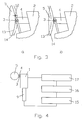
- the engraving head 2 can be seen in the front view in the direction of arrow A of Figure 1.
- the distance measuring element 4 is provided as a capacitive sensor directly next to the engraving stylus 3, so that the Distance measuring point and the engraving point for the grid cells are close to each other.
- this lies on a grid line which lies in the direction of movement of the engraving stylus 3.
- a precise correction of the tool distance W can be carried out on the basis of the measured distance by means of a suitable electronic delay. This delay can be derived from the distance between the measuring location and the processing point of the engraving stylus 3 and from the speed of movement of the engraving stylus 3 along the grid line.
- An air-blowing nozzle 11 is arranged next to the distance measuring element 4 and blows away dust and adhering metal chips on the surface of the gravure cylinder 2 from the engraved cylinder surface.
- a suction device (not shown) can additionally be provided below the engraving head 2 in order to be able to effectively remove the contaminants in the form of dust, metal chips and the like.
- FIG. 3a shows a detail of the engraving head 2 from FIG. 1 on an enlarged scale.
- the narrow gap 12 between the cylinder surface 13 of the gravure cylinder 5 with a precisely circular cylindrical shape and the measuring surface of the capacitive sensor 4 is clearly visible.
- Compressed air is applied to the air-blowing nozzle 11 in order to blow the impurities out of the gap 12 in the order of magnitude of 250 ⁇ m.
- Dashed lines indicate an out-of-roundness 14 of the cylinders 5 as a deviation of the cylinder surface 13 from the ideal circular cylindrical shape.
- the out-of-roundness 14 is drawn in solid lines in FIG. 3b and causes a tilting movement of the lifting platform 6 about the axis of rotation 7, ie an adaptation of the tool distance W of the engraving stylus 3.
- the air-blowing nozzle can also be used as an annular nozzle (not shown here) be formed, which extends around the capacitive distance sensor 4 and forms a kind of protective curtain made of compressed air around it and thus always keeps a clean measuring surface on the cylinder surface 13 free.
- the electronic control for tracking the tool distance of the engraving stylus 3 is shown schematically in FIG. 4 on the basis of the distance measured by the distance measuring element 4.
- the engraving head 2 with the piezoelectric drive 9, which is electrically connected to a drive control 15, is shown adjacent to the gravure cylinder 5.
- This drive control 15 is connected to an electronic circuit 17 for distance measurement via a control 16.
- the measured distance signal is compared as the actual value W Ist with a predetermined target value W Soll , which represents the ideal tool distance, and passed on to the controller 16 as a control signal.
- this control signal is processed as a control signal for the drive control 15 by a suitable time delay and signal amplification.
- This circuit thus forms a simple control loop in order to keep the tool distance W of the engraving stylus 3 constant with respect to the cylinder surface 13.
- the distance measuring element 4 is designed as a capacitive distance sensor.
- this can advantageously also be an inductive or optical distance sensor.
- a pneumatic distance sensor such as a dynamic pressure sensor known from sheet metal processing with lasers, can also be used for this purpose, in which case the air-blowing nozzle 11 is omitted, since the cleaning function is simultaneously taken over by such a sensor.
- an adjusting element 9 can instead of a piezoelectric Drive an electromagnetic drive in the form of an electrostrictive or magnetostrictive actuator can be used, as known from automotive technology in connection with so-called ABS systems.
- a precise servo motor or a hydraulic drive can also be used instead of the piezoelectric drive.
- the adjusting element 9 in the form of one of the drives mentioned above is normally linearly movable, since the lifting platform 6 only needs to perform a slight tilting movement.
- the engraving stylus 3 can be driven either in a conventional manner or by means of a piezoelectric drive unit which is controlled in a suitable manner.
Landscapes
- Engineering & Computer Science (AREA)
- Mechanical Engineering (AREA)
- Manufacturing & Machinery (AREA)
- Physics & Mathematics (AREA)
- General Physics & Mathematics (AREA)
- Manufacture Or Reproduction Of Printing Formes (AREA)
Applications Claiming Priority (2)
| Application Number | Priority Date | Filing Date | Title |
|---|---|---|---|
| CH127495 | 1995-05-02 | ||
| CH274/95 | 1995-05-02 |
Publications (2)
| Publication Number | Publication Date |
|---|---|
| EP0741008A2 true EP0741008A2 (fr) | 1996-11-06 |
| EP0741008A3 EP0741008A3 (fr) | 1998-05-13 |
Family
ID=4206591
Family Applications (1)
| Application Number | Title | Priority Date | Filing Date |
|---|---|---|---|
| EP96105870A Withdrawn EP0741008A3 (fr) | 1995-05-02 | 1996-04-15 | Appareil pour graver des cylindres d'impression |
Country Status (1)
| Country | Link |
|---|---|
| EP (1) | EP0741008A3 (fr) |
Cited By (2)
| Publication number | Priority date | Publication date | Assignee | Title |
|---|---|---|---|---|
| WO2004056568A3 (fr) * | 2002-12-20 | 2005-01-13 | Giesecke & Devrient Gmbh | Procede et dispositif pour fabriquer des plaques d'impression helio et plaque d'impression ainsi fabriquee |
| EP1900517A1 (fr) * | 2006-09-12 | 2008-03-19 | MDC Max Dätwyler AG | Appareil pour produire des structures gaufrées sur la surface d'un cylindre |
Family Cites Families (3)
| Publication number | Priority date | Publication date | Assignee | Title |
|---|---|---|---|---|
| GB1498811A (en) * | 1974-03-01 | 1978-01-25 | Crosfield Electronics Ltd | Preparation of gravure printing cylinders |
| DE3201178A1 (de) * | 1982-01-16 | 1983-07-28 | M.A.N.- Roland Druckmaschinen AG, 6050 Offenbach | "vorrichtung zum einstellen einer rakel in einer rotationstiefdruckmaschine auf den jeweiligen formzylinderdurchmesser" |
| CH672458A5 (fr) * | 1986-10-02 | 1989-11-30 | Daetwyler Ag |
-
1996
- 1996-04-15 EP EP96105870A patent/EP0741008A3/fr not_active Withdrawn
Cited By (3)
| Publication number | Priority date | Publication date | Assignee | Title |
|---|---|---|---|---|
| WO2004056568A3 (fr) * | 2002-12-20 | 2005-01-13 | Giesecke & Devrient Gmbh | Procede et dispositif pour fabriquer des plaques d'impression helio et plaque d'impression ainsi fabriquee |
| EP1900517A1 (fr) * | 2006-09-12 | 2008-03-19 | MDC Max Dätwyler AG | Appareil pour produire des structures gaufrées sur la surface d'un cylindre |
| WO2008031242A3 (fr) * | 2006-09-12 | 2008-07-10 | Mdc Max Daetwyler Ag | Dispositif de formation de structures de gaufrage dans une surface d'un cylindre |
Also Published As
| Publication number | Publication date |
|---|---|
| EP0741008A3 (fr) | 1998-05-13 |
Similar Documents
| Publication | Publication Date | Title |
|---|---|---|
| EP2097261B9 (fr) | Presse rotative et procédé pour ajuster un de ses cylindres | |
| DE102006008464B4 (de) | Eindruckeinrichtung | |
| DE102016002765B3 (de) | Vorrichtung mit Presse, Werkzeug und Werkzeugschutzsystem zur Bearbeitung von Blechwerkstücken und hierfür verwendbare einstellbare Distanzeinrichtung | |
| EP2832546A1 (fr) | Imprimante dotée d'une commande de tête d'impression | |
| DE68927482T2 (de) | Positionierungsmechanismus und -verfahren | |
| EP2092991B1 (fr) | Matrice à plier pour une presse à plier, notamment presse plieuse et procédé de pliage d'une pièce | |
| EP0377796A2 (fr) | Dispositif de mesure et de dégauchissage pour rectifieuse cylindrique | |
| DE69104766T2 (de) | Schneidemachine und Abschneideverfahren mit dieser Maschine. | |
| DE69413611T2 (de) | Verfahren und Vorrichtung zur Einstellung des Abstandes zwischen einem Werkstück und einer Maske | |
| DE202007004717U1 (de) | Rotationsdruckmaschine | |
| DE69904769T2 (de) | Verfahren sowie Vorrichtung zum Bearbeiten von Blattförmigen Materialen | |
| DE3821548C2 (fr) | ||
| EP0925188B1 (fr) | Procede et dispositif pour la commande d'un dispositif de gravage | |
| CH689669A5 (de) | Vorrichtung zum Gravieren von Tiefdruckzylindern. | |
| EP0741008A2 (fr) | Appareil pour graver des cylindres d'impression | |
| DE3914059C2 (fr) | ||
| DE102019135740B4 (de) | Haltevorrichtung mit elastischem Federelement und pneumatischem Kanalsystem; Bestückkopf und Bestückautomat sowie Verfahren zum Bestücken von Bauelementeträgern | |
| DE102007032088B4 (de) | Vorschubeinrichtung für einen Mehrkoordinaten-Messtisch eines Koordinaten-Messgeräts | |
| EP0603526B1 (fr) | Dispositif et procédé d'usinage par électro-érosion | |
| EP1762818B1 (fr) | Tête de palpage | |
| DE102005006242A1 (de) | Schleifmaschine und Verfahren zum Einrichten eines Werkstückträgers an einer Schleifmaschine | |
| EP1528981A1 (fr) | Cylindres d'une presse rotative et unite d'impression | |
| DE102019127817A1 (de) | Computerimplementiertes Verfahren zur Steuerung einer Siebdruckmaschine, computergesteuerte Siebdruckmaschine | |
| DE19961869B4 (de) | Justiervorrichtung, insbesondere für Traversen mit Bebilderungseinrichtungen für Druckformen von Druckmaschinen | |
| DE102018103398B4 (de) | Pneumatisch aktuierbares Federelement zum Steuern der auf ein Bauelement wirkenden Bestückkraft |
Legal Events
| Date | Code | Title | Description |
|---|---|---|---|
| PUAI | Public reference made under article 153(3) epc to a published international application that has entered the european phase |
Free format text: ORIGINAL CODE: 0009012 |
|
| AK | Designated contracting states |
Kind code of ref document: A2 Designated state(s): DE FR GB IT |
|
| GBC | Gb: translation of claims filed (gb section 78(7)/1977) | ||
| PUAL | Search report despatched |
Free format text: ORIGINAL CODE: 0009013 |
|
| AK | Designated contracting states |
Kind code of ref document: A3 Designated state(s): DE FR GB IT |
|
| 17P | Request for examination filed |
Effective date: 19980630 |
|
| 17Q | First examination report despatched |
Effective date: 19990422 |
|
| GRAG | Despatch of communication of intention to grant |
Free format text: ORIGINAL CODE: EPIDOS AGRA |
|
| STAA | Information on the status of an ep patent application or granted ep patent |
Free format text: STATUS: THE APPLICATION IS DEEMED TO BE WITHDRAWN |
|
| 18D | Application deemed to be withdrawn |
Effective date: 20001101 |