EP0740928A2 - Selbstexpandierender Stent zur Einführung einer medizinischen Vorrichtung in eine Körperhöhle und Herstellungsverfahren - Google Patents
Selbstexpandierender Stent zur Einführung einer medizinischen Vorrichtung in eine Körperhöhle und Herstellungsverfahren Download PDFInfo
- Publication number
- EP0740928A2 EP0740928A2 EP96200816A EP96200816A EP0740928A2 EP 0740928 A2 EP0740928 A2 EP 0740928A2 EP 96200816 A EP96200816 A EP 96200816A EP 96200816 A EP96200816 A EP 96200816A EP 0740928 A2 EP0740928 A2 EP 0740928A2
- Authority
- EP
- European Patent Office
- Prior art keywords
- tubular body
- diameter
- wires
- state
- threads
- Prior art date
- Legal status (The legal status is an assumption and is not a legal conclusion. Google has not performed a legal analysis and makes no representation as to the accuracy of the status listed.)
- Granted
Links
Images


Classifications
-
- A—HUMAN NECESSITIES
- A61—MEDICAL OR VETERINARY SCIENCE; HYGIENE
- A61F—FILTERS IMPLANTABLE INTO BLOOD VESSELS; PROSTHESES; DEVICES PROVIDING PATENCY TO, OR PREVENTING COLLAPSING OF, TUBULAR STRUCTURES OF THE BODY, e.g. STENTS; ORTHOPAEDIC, NURSING OR CONTRACEPTIVE DEVICES; FOMENTATION; TREATMENT OR PROTECTION OF EYES OR EARS; BANDAGES, DRESSINGS OR ABSORBENT PADS; FIRST-AID KITS
- A61F2/00—Filters implantable into blood vessels; Prostheses, i.e. artificial substitutes or replacements for parts of the body; Appliances for connecting them with the body; Devices providing patency to, or preventing collapsing of, tubular structures of the body, e.g. stents
- A61F2/82—Devices providing patency to, or preventing collapsing of, tubular structures of the body, e.g. stents
- A61F2/86—Stents in a form characterised by the wire-like elements; Stents in the form characterised by a net-like or mesh-like structure
- A61F2/90—Stents in a form characterised by the wire-like elements; Stents in the form characterised by a net-like or mesh-like structure characterised by a net-like or mesh-like structure
-
- D—TEXTILES; PAPER
- D04—BRAIDING; LACE-MAKING; KNITTING; TRIMMINGS; NON-WOVEN FABRICS
- D04C—BRAIDING OR MANUFACTURE OF LACE, INCLUDING BOBBIN-NET OR CARBONISED LACE; BRAIDING MACHINES; BRAID; LACE
- D04C1/00—Braid or lace, e.g. pillow-lace; Processes for the manufacture thereof
- D04C1/06—Braid or lace serving particular purposes
-
- A—HUMAN NECESSITIES
- A61—MEDICAL OR VETERINARY SCIENCE; HYGIENE
- A61F—FILTERS IMPLANTABLE INTO BLOOD VESSELS; PROSTHESES; DEVICES PROVIDING PATENCY TO, OR PREVENTING COLLAPSING OF, TUBULAR STRUCTURES OF THE BODY, e.g. STENTS; ORTHOPAEDIC, NURSING OR CONTRACEPTIVE DEVICES; FOMENTATION; TREATMENT OR PROTECTION OF EYES OR EARS; BANDAGES, DRESSINGS OR ABSORBENT PADS; FIRST-AID KITS
- A61F2230/00—Geometry of prostheses classified in groups A61F2/00 - A61F2/26 or A61F2/82 or A61F9/00 or A61F11/00 or subgroups thereof
- A61F2230/0063—Three-dimensional shapes
- A61F2230/0073—Quadric-shaped
- A61F2230/0078—Quadric-shaped hyperboloidal
Definitions
- the present invention relates to a self-expanding stake for a medical device to be introduced into a cavity of a human or animal body, comprising a radially expandable tubular body which is retractable between a first diameter, corresponding to a work state of the stake, and a second diameter greater than the first, corresponding to a state of rest of the tutor, and axially expandable and retractable between a first length, corresponding to the working state, and a second length less than the first, corresponding to the state of rest , this tubular body comprising first flexible rigid wires wound in a first direction around a longitudinal axis of the tubular body and second flexible rigid wires wound in a second direction opposite to the first around the said longitudinal axis, each fit wound in one of said directions crossing wires wound in the other direction according to a braided arrangement, wires aforementioned can be presented in the form of at least one multiple fit.
- Tutors have long been known to be used as vascular, esophageal or other dilators (GB-1205743). These stakes formed of a tubular braid of individual threads comprise, in the state of rest, threads forming a fairly small angle with respect to a generator of the tube, that is to say at most 30 °. Guardians of this kind do not provide sufficient radial expansion capacity when released after being radially compressed. Their crushing resistance is also insufficient when used in body cavities whose walls exert a strong radial pressure on the introduced support.
- the tubular structure When dropped, the tubular structure retracts two to three times in length. It is therefore very difficult to estimate the length that will deploy in the internal cavity of the body being treated and the precise location where the tutor will anchor, which can cause serious problems.
- a stake length can extend beyond a vascular bifurcation and thus lead to undesirable artery closure, when the stake is covered with a covering, as is the case with luminal stents.
- the treated aneurysm will not be closed.
- tutors with a large braiding angle and individual wires did not exhibit good resistance to blood pressure, inside the treated aneurysms. Inside the aneurysm, that is to say where the guardians do not undergo more radial compression on the part of the vascular wall, the latter tend to balloon, which promotes leaks.
- tubular braids based on threads which are used in devices to be introduced into the human body, are also described in particular in EP-A-0183372, US-A-3509883, US-A-5061275 and US-A- 5171262.
- the braided filaments are in the form of a multiple thread, three filaments being respectively twisted together in a strand to form the multiple thread.
- the braided filaments will be difficult to apply. It will have an unbearable volume size and at the point of crossing between the strands there will be significant friction.
- it will be complicated to reduce the diameter of the stake sufficiently enough to be able to insert it into an introducer. In metal filaments, these will suffer enormously and breakage cannot be excluded.
- each aforesaid multiple threads comprises the above flexible rigid threads, which are arranged side by side at least as many two following a parallel route in the braided layout.
- a tutor has great dimensional and geometric stability, without requiring a large braiding angle and, therefore, the release precision of this tutor is greatly increased.
- the diameter of such a stake can be reduced without problem to that of a common introducer, the multiple wires used according to the invention having no obstacle to this.
- all of the above-mentioned first wires and all of the above-mentioned second wires form multiple wires.
- self-expanding tutor it should be understood according to the invention that, brought into its working position, that is to say a radially compressed and axially extended position, the tutor, once released, tends to spontaneously recover its position of rest, that is to say a radially expanded and axially contracted position.
- a first multiple thread will, when crossing with a second multiple thread, pass over the latter and during the following crossing pass below the second thread then crossed , And so on.
- the first multiple thread passes over a second multiple thread at two or more successive crosses and will then only pass below a second multiple thread after several successive crosses and so on.
- Mixed braided arrangements can also be provided, as well as braids partially formed from double threads and monofilaments.
- the flexible rigid threads which form them, are placed side by side and follow a parallel path in the braided arrangement.
- two neighboring wires no longer follow the same route, that is to say for example that one crosses a wound wire in the opposite direction by passing over it while the other crosses the same wound wire in opposite direction by passing below, it is no longer a question of wires forming a multiple wire within the meaning of the present invention.
- the wires forming the same multiple wire can be joined or arranged at a very short distance from each other.
- medical device to be introduced into a cavity of a human or animal body is intended to mean, for example, luminal stents, catheters, dilators, grafts and the like which can be introduced for example into vascular, esophageal, urinary, ureteral, biliary, and other tubular conduits of the body.
- the tubular body formed of braided multiple threads presents, in the state of rest, a flare where the multiple threads follow a spatial spiral with increasing rays.
- a flare where the multiple threads follow a spatial spiral with increasing rays.
- the tutor according to the invention in particular its flared end, has a resistance to crushing by the arterial wall due to the narrowing of the collar. The radial expansion of the flared part of the support also promotes the absence of migration along the wall of the cavity where it must be applied.
- the tubular body of the stake comprises, in the state of rest, two flared ends of large diameter and, between them, a cross section of tubular body of small diameter and that, from each of the flared ends to the small diameter section, the tubular body in cross section has a continuously decreasing diameter.
- the tutor opposes any bloating inside an aneurysm, while retaining its good attachment properties by its flared ends, when dropping a human body into a tubular cavity. animal. And that, even if the surgeon cut part of the length of the tutor by cutting. The new end formed remains still flared compared to the rest of the tutor.
- the radial relaxation of the flared parts of the tutor remains maintained during the release, and the flared parts, by perfectly matching the shapes of the vascular walls where they are released effectively prevent migration of the tutor along these walls.
- the tubular body comprises a generator in the form of a straight line.
- the tubular body comprises a generator in the form of a half-hyperbola.
- the tutor has a form of hyperboloid.
- the tubular body comprises a generator in the form of a segment of a circle.
- the tubular body advantageously comprises multiple wires oriented at an angle equal to, preferably less than, 45 ° relative to one of its generatrices.
- the braiding angle does not need to be large, to obtain good dimensional stability properties. Consequently, there results a significant improvement in the release of the tutor into the cavity where it is to be applied.
- the tubular body has an external wall surface and an internal wall surface and it comprises on at least one of these two wall surfaces an expandable covering.
- a covering can be applied to the tutor according to any known technique, for example in accordance with the teaching of EP-A-0603959.
- This makes it possible, for example, to form luminal stents 40 mm in diameter at rest, the covering of which is made of polycarbonate-urethane fibers or the like with a fiber diameter of 10-20 ⁇ m.
- the diameter of such stents can then be reduced to a diameter of 4 to 5 mm for insertion into an introducer. It is understood that the recovery can be of a different nature and that it can be carried out according to other well known techniques, without departing from the scope of the invention.
- the invention also relates to a medical device to be introduced into a cavity of a human or animal body, which comprises a self-expanding stakeholder according to the invention.
- a method for preparing a self-expanding tutor for a medical device to be introduced into a body cavity comprising a braiding of threads coming from interposed spindles rotating in opposite directions, so as to form a radially expandable and retractable tubular body between a first diameter, corresponding to a working state of the tutor, and a second diameter greater than the first, corresponding to a state of rest of the tutor, and axially expandable and retractable between a first length, corresponding to the working state, and a second length less than the first, corresponding to the rest state, the braiding comprising a winding of flexible first rigid wires in a first helical direction around a longitudinal axis of the tubular body and a winding second flexible rigid wires in a second helical direction opposite to the first, each wire wound d in one of said helical directions crossing multiple wires wound in the other helical direction, aforementioned threads which may be in the form of at least one multiple thread
- the process described above comprises, before braiding, an emptying of at least one spindle by said threads arranged side by side at least two in number, to form said at least one thread. multiple, and, during winding, the wires forming a multiple wire follow a parallel path.
- Such a method allows the manufacture of a tutor much more efficient than those of the prior art, without having to modify the existing apparatus, and therefore without additional investment. It also does not include a prior step of manufacturing a multi-wire, such as a strand for example.
- the method comprises braiding the tubular body to a diameter greater than the second diameter mentioned above, an axial expansion of the braided tubular body, in particular by its introduction into a tube with a predetermined internal shape, and a heat treatment for hardening the tubular body thus axially expanded to fix it so that, after this treatment, it is in the rest state when it has a shape corresponding to that of the internal cavity of the tube.
- This embodiment makes it possible to obtain angles between the wires and a generator of the stake which are perfectly reproducible after the step of fixing the tubular body in its shape corresponding to the state of rest.
- the tube can have any suitable shape, for example cylindrical or hyperboloid cavity.
- the stake after the introduction of the braided tubular body into said tube, at least one of its ends protrudes from the tube, flaring out.
- the stake after the aforementioned hardening heat treatment, the stake can be fixed, in the rest state, with a flare at at least one of its ends.
- the flare in question can automatically take a form such that it includes a generator in the form of a hyperbola segment.
- the method comprises, after braiding, threading the braided tubular body around a mandrel of suitable shape, a tension at the ends of the tubular body to apply it to the mandrel, a heat treatment for hardening the tubular body thus axially stretched to fix it so that, after this treatment, it has the shape of the mandrel in the state of rest.
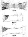
- Figure 1 shows a side view of an end portion of an embodiment of a self-expanding stakeholder according to the invention.
- FIG. 1A represents, on an enlarged scale, a detail of the braiding of the multiple threads of the tutor of FIG. 1.
- FIG. 2 represents a side view of an end part of a second embodiment of a tutor according to the invention.
- FIG. 3 represents a side view of an end part of a third embodiment of a tutor according to the invention.
- FIG. 4 represents a side view of a fourth embodiment of a self-expanding tutor according to the invention.
- FIG. 5 represents a side view of a fifth embodiment of a tutor according to the invention.
- Figure 6 shows a side view of a sixth embodiment of a tutor according to the invention.
- Figure 7 shows a general diagram of the braiding apparatus and Figure 8 a more detailed view of the braiding operation.
- FIG. 9 represents a partial view of a tutor according to the invention at the end of manufacture.
- the self-expanding stakeholder is formed of a tubular body 1 having at the illustrated end a cylindrical shape.
- the tubular body 1 is formed of braided wires. It comprises first flexible rigid wires, for example 2 and 3, which are arranged side by side, here two in number, and which thus form first multiple wires wound in a first helical direction around the longitudinal axis 4 of the body tubular.
- second rigid wires 5 and 6 which are arranged side by side, here two in number, and which thus form multiple second wires wound in a second helical direction, opposite to the first. It is obvious that three, four or more wires can be provided arranged side by side to form a multiple wire according to the invention (see for example FIG. 5). It should also be noted that the wires arranged side by side to form a multiple wire are contiguous over almost their entire length. It is only for reasons of clarity and legibility of the figures that the wires forming a multiple wire, such as wires 2 and 3 or respectively 5 and 6, are shown slightly spaced from one another.
- the braiding mode can be variable as already indicated above. It appears in particular from FIG. 1A, that all the flexible wires forming the same multiple wire within the meaning of the invention follow a strictly parallel path in the braid.
- the multiple threads used consist of any material which is suitable for introduction into the human and animal body and which has sufficient rigidity and flexibility for the production of a self-expanding stake.
- Such threads meeting ISO 5832/7 and / or ASTM F1058-91 standards are highly desirable.
- the tubular body is shown in the rest state. In this state it presents, in this exemplary embodiment, a diameter D of approximately 28 mm. Its length is to be chosen according to the use of the tutor.
- the tutor In its working state, that is to say when it must be introduced into a known introducer, not shown, the tutor must have a diameter d which can reach 3 to 4 mm.
- the working state is obtained by radial compression on the tutor and / or by spacing the ends of the tutor in the axial direction. In the working state, the tutor therefore has a length greater than its length in the rest state.
- the arrangement of multiple wires according to the invention does not in any way hinder the obtaining of this working state of the tutor.
- the wires In this state of rest, the wires have, in the illustrated embodiments, with respect to a generator (7 in FIG. 2) of the tutor an angle of maximum 45 °, preferably less than this.
- This offers the great advantage that the tutor, in the working state, inserted in his introducer, does not have an excessive length with all the disadvantages of dropping that this raises, as already indicated previously.
- an angle of 45 ° is not critical for the invention and may, depending on the circumstances, be exceeded.
- the tubular body 1 can be coated on its internal surface with a covering 8 partially shown.
- This covering can be of any suitable biocompatible material, in particular for the manufacture of luminal stents (see EP-A-0603959).
- a covering on the external surface can be provided instead of the internal covering 8 or simultaneously with it.
- the use of multiple threads according to the invention also offers the advantage of a relatively large contact surface to have better adhesion with such a covering.
- FIG. 2 a tutor according to the invention is illustrated, the tubular body 1 of which has a flare at one end 9.
- the multiple wires follow a spatial spiral with increasing rays.
- the generator 7, at the place of the flare 9 forms a straight line which progressively deviates towards the outside of the axis 4.
- the flare 9 is therefore here of frustoconical shape.
- FIG. 3 a stake is illustrated, the tubular body 1 of which has a flare 10 at one end, the generator of which has the shape of a hyperbola segment.
- This flare gives rise to one end 10 of the stake 1, in the form of a truncated hyperboloid.
- the self-expanding stakeholder according to the invention is formed of a tubular body 1 having, in this example, a form of hyperboloid.
- the tubular body 1 is shown in the rest state. In this state it has, in this embodiment, a first flared end 11 of diameter D 1 and a second flared end 12 of diameter D 2 equal to D 1 . Halfway between these two flared ends is located a cross section 13 of the tubular body whose diameter D 3 is less than D 1 and D 2 .
- the diameter D 3 may for example be around 28 mm, and the diameters D 1 and D 2 equal for example 58 mm.
- the tubular body 1 has, in cross section, a diameter which decreases continuously. In the illustrated case, this reduction is such that the tubular body includes a generator 7 in the form of a hyperbola.
- the wires In the rest state, the wires have, in this illustrated embodiment, with respect to a generator 7 of the tutor an angle ⁇ which varies constantly. In its central part, this angle is preferably at most 45 °, advantageously less than this value. At the flared ends it is obviously much larger. This offers the great advantage that the tutor, in the working state, inserted in his introducer, does not have an excessive length with all the disadvantages of dropping that this raises, as already indicated previously. Furthermore, the radial relaxation of the ends is excellent and allows good attachment of the tutor, preventing migration of the latter during or after the release.
- FIG. 5 a tutor according to the invention is illustrated, the tubular body 1 of which has a first flared end 11 of diameter D 1 and a second end 12 of diameter D 2 less than D 1 .
- the cross section 13 of small diameter D 3 is located here at a shorter distance from the end 12 than from the end 11, which gives rise to a tubular body of asymmetrical shape.
- the tubular body comprises a straight-shaped generator, which progressively deviates outwards from the longitudinal axis 4, which gives rise to a form of tapered diabolo.
- the multiple wires braided according to a helix with increasing spokes have been shown in a partially broken manner.
- each multiple thread includes 3 threads arranged side by side.
- FIG. 6 a tutor is illustrated, the tubular body 1 of which has between its flared ends a generator in the form of a segment of a circle.
- the embodiments according to the invention illustrated in Figures 2 to 6 offer the great advantage of allowing good attachment of the guardian during the release, without subsequent migration into the cavity.
- the attachment to the wall thereof is more intense at the end which is the first dropped, thanks to its flared shape, and this retains the dropped device in the position that has been imposed on it.
- Such a tutor according to the invention proves to be very advantageous in particular during the introduction of a stent to treat an abdominal artery aneurysm. Its two ends follow the shape of the necks of the aneurysm, thus perfectly retaining the endoprosthesis, which is subjected at this point to the stresses of blood pressure.
- the central part of the tutor according to Figures 4 to 6, arched inward and recalled in this direction, perfectly withstands this blood pressure in the aneurysm, where no more radial compression is exerted on the tutor by the walls vascular.
- the stakes according to FIGS. 2 to 6 are also quite suitable for the treatment of subclavian artery aneurysms, where the stent can be strongly bent at one end. Instead of being crushed by closing at this end, like the cylindrical stakes of the prior art, the stake remains in a widely open position at its end, thanks to the shape thereof.
- FIGS. 7 and 8 appended The manufacture of a braided tubular body has been known for a long time in the cabling technique and use is made here of this technique which is illustrated in FIGS. 7 and 8 appended.
- a carrying cable 14 is unwound from a reel 15.
- a guide system generally designated by the reference 16 guides and brings under tension this cable 14 which then passes through the braiding machine 17 shown diagrammatically here. It leaves this machine, provided with a braided tubular body and it is thus wound on a coil 18 after having been brought under tension by a new guidance system 19.
- the braiding machine 17 used is shown in a little more detail in FIG. 8.
- a braiding machine of this kind it is possible, for example, to use a machine of the DBH or DB model put on the market by the firm Spiraltex, Meximieux, France.
- the spindles of such a machine (of which only a few have been shown) are divided into two groups, the spindles 20 of one group rotating in the opposite direction to the spindles 21 of the other group, around the axis of the braid.
- the carrying cable 14, not shown here, passes vertically through the middle of the braid.
- multiple threads 22 are unwound from each or part of the spindles.
- several threads were simultaneously wound on at least part of the spindles, preferably on all.
- these multiple threads coming from the spindles are almost contiguous over their entire length and that is why it was impossible to represent them in FIG. 8 other than in the form of a thread.
- the choice of the number of spindles depends on the diameter of the braid 23 desired.
- the braided tubular body has, at the end of the braiding, a diameter slightly greater than the diameter (for example D or D 3 ) of the finished tutor, in the rest state.
- the braided tubular body can then be removed from its carrying cable.
- this mandrel therefore has the shape of a cylinder of diameter, for example D, carrying a truncated cone at one end.
- the braided tubular body is then subjected to axial tension at its ends. It is for example, as in FIG. 9, knotted at 26 at one end, then at the other, which subjects it to a tension.
- the tubular body then follows the external shape of the mandrel 24. It is then subjected to a hardening heat treatment which fixes the tubular body to the dimensions of the mandrel. After this treatment, in the resting state, the tubular body has the shape illustrated in FIG. 2 or respectively in FIG. 4.
- the braided tubular body it is also provided, as a variant, to extend the braided tubular body and to introduce it into a tube 25, shown in lines. mixed in Figure 3 or Figure 6, which has an internal diameter equal to the desired diameter of the finished tutor. It is then subjected to the hardening heat treatment.
- a tubular braid 35 mm in diameter is introduced into a tube 28 mm in internal diameter.
- the wire is cured at 550 ° C for 3 hours, under an inert atmosphere (argon or nitrogen with 5% hydrogen) or under a vacuum of 10-5 torr.
- the finished tutor has a cylindrical shape as in the embodiment according to FIG. 1. If, on the other hand, one or more the two ends of the braid protrude from the tube 25 according to FIG. 3, these will automatically take the form of a truncated hyperboloid, as illustrated in this FIG. 3.
- the measurement method in these examples consists in evaluating the resistance to radial compression of the stakes.
- a loop of 0.12 mm diameter wire, attached at one end to a support, is passed around the stake to be examined, approximately in the middle of the support.
- Different weights are then suspended from the other end of the wire and the diameter is then measured at the constriction obtained for each weight suspended from the measuring wire.
- the tutor according to the prior art has in the state of rest a diameter of 32.77 mm and an angle of 52 °.
- the tutor according to the invention has in the idle state a diameter of 31.4 mm and an angle of 51 °.
- the angle of the wires with respect to a generator is 66 ° for the tutor according to the prior art, it is 49 ° for a tutor X according to the invention and 44 ° for a tutor Y according to the invention.
- the three examined stakes have an identical length, that is to say of approximately 10 cm.
- the tutor according to the prior art and the tutor Y were then introduced into an ID5 type Balt introducer (5 mm internal diameter) with a length of 50 cm.
- the tutor according to the prior art occupies a length of 44 cm, the tutor Y a length of 18 cm.
- the AC stakes have a diameter in the state of rest of 32 mm.
- the wires of the stakes A and B have an angle to a generator of 53.75 ° and 53.25 ° respectively, those of the stake C an angle of 55 °.
- stakes A and B can be manufactured on the same braiding machines as those used up to now (for example with 36 spindles).
Landscapes
- Health & Medical Sciences (AREA)
- Engineering & Computer Science (AREA)
- Biomedical Technology (AREA)
- Heart & Thoracic Surgery (AREA)
- Life Sciences & Earth Sciences (AREA)
- Cardiology (AREA)
- Oral & Maxillofacial Surgery (AREA)
- Transplantation (AREA)
- Manufacturing & Machinery (AREA)
- Vascular Medicine (AREA)
- Textile Engineering (AREA)
- Animal Behavior & Ethology (AREA)
- General Health & Medical Sciences (AREA)
- Public Health (AREA)
- Veterinary Medicine (AREA)
- Prostheses (AREA)
- Materials For Medical Uses (AREA)
- Media Introduction/Drainage Providing Device (AREA)
Applications Claiming Priority (4)
| Application Number | Priority Date | Filing Date | Title |
|---|---|---|---|
| BE9500335A BE1009278A3 (fr) | 1995-04-12 | 1995-04-12 | Tuteur auto-expansible pour dispositif medical a introduire dans une cavite d'un corps, et dispositif medical muni d'un tel tuteur. |
| BE9500335 | 1995-04-12 | ||
| BE9500334A BE1009277A3 (fr) | 1995-04-12 | 1995-04-12 | Tuteur auto-expansible pour dispositif medical a introduire dans une cavite d'un corps, et son procede de preparation. |
| BE9500334 | 1995-04-12 |
Publications (3)
| Publication Number | Publication Date |
|---|---|
| EP0740928A2 true EP0740928A2 (de) | 1996-11-06 |
| EP0740928A3 EP0740928A3 (de) | 1997-01-29 |
| EP0740928B1 EP0740928B1 (de) | 2004-07-07 |
Family
ID=25662977
Family Applications (1)
| Application Number | Title | Priority Date | Filing Date |
|---|---|---|---|
| EP96200816A Expired - Lifetime EP0740928B1 (de) | 1995-04-12 | 1996-03-27 | Selbstexpandierender Stent zur Einführung einer medizinischen Vorrichtung in eine Körperhöhle und Herstellungsverfahren |
Country Status (3)
| Country | Link |
|---|---|
| EP (1) | EP0740928B1 (de) |
| AT (1) | ATE270528T1 (de) |
| DE (1) | DE69632844T2 (de) |
Cited By (44)
| Publication number | Priority date | Publication date | Assignee | Title |
|---|---|---|---|---|
| EP0861638A3 (de) * | 1997-02-27 | 1998-11-11 | Corvita Corporation | Modulares endoluminales Stent-Gewebe |
| EP0880946A1 (de) | 1997-05-27 | 1998-12-02 | MEDICORP R&D BENELUX | Selbstexpandierende Endoprothese |
| EP0857471A3 (de) * | 1997-02-04 | 1998-12-02 | Solco Surgical Instruments Co., Ltd. | Stent zum Expandieren eines Körperlumens |
| WO1999025271A1 (de) * | 1997-11-18 | 1999-05-27 | Schneider (Europe) Gmbh | Stent zur implantation im menschlichen körper, insbesondere in blutgefässe |
| WO1999055256A1 (en) * | 1998-04-28 | 1999-11-04 | Intratherapeutics, Inc. | Braided stent |
| FR2779938A1 (fr) * | 1998-06-17 | 1999-12-24 | Perouse Implant Lab | Necessaire de traitement d'un vaisseau sanguin |
| WO2000000105A1 (en) | 1998-06-30 | 2000-01-06 | Scimed Life Systems, Inc. | Implantable endoprosthesis with patterned terminated ends and methods for making same |
| US6042589A (en) * | 1998-03-17 | 2000-03-28 | Medicorp, S.A. | Reversible-action endoprosthesis delivery device |
| US6077296A (en) * | 1998-03-04 | 2000-06-20 | Endologix, Inc. | Endoluminal vascular prosthesis |
| US6090128A (en) * | 1997-02-20 | 2000-07-18 | Endologix, Inc. | Bifurcated vascular graft deployment device |
| WO2000033770A3 (en) * | 1998-12-09 | 2000-08-10 | Gore Enterprise Holdings Inc | Multi-stage expandable stent-graft |
| US6146403A (en) * | 1997-05-22 | 2000-11-14 | Scimed Life Systems, Inc. | Variable expansion force stent |
| US6159228A (en) * | 1997-05-20 | 2000-12-12 | Frid; Noureddine | Applicator for luminal endoprostheses |
| US6231573B1 (en) | 1998-04-21 | 2001-05-15 | Medicorp, S.A. | Device for treating aneurysms |
| US6348066B1 (en) | 1995-11-07 | 2002-02-19 | Corvita Corporation | Modular endoluminal stent-grafts and methods for their use |
| US6379379B1 (en) | 1998-05-05 | 2002-04-30 | Scimed Life Systems, Inc. | Stent with smooth ends |
| US6389946B1 (en) | 1997-01-16 | 2002-05-21 | Medicorp R & D Benelux S.A. | Method for manufacturing braided multifilament structures for an endoprosthesis for ramification of an anatomical conduit |
| US6500202B1 (en) | 1998-12-11 | 2002-12-31 | Endologix, Inc. | Bifurcation graft deployment catheter |
| US6508835B1 (en) | 1998-12-11 | 2003-01-21 | Endologix, Inc. | Endoluminal vascular prosthesis |
| WO2003051234A1 (en) * | 2001-12-17 | 2003-06-26 | Advanced Cardiovascular Systems, Inc. | Stent for treating bifurcations and method of use |
| US6660030B2 (en) | 1998-12-11 | 2003-12-09 | Endologix, Inc. | Bifurcation graft deployment catheter |
| US6733523B2 (en) | 1998-12-11 | 2004-05-11 | Endologix, Inc. | Implantable vascular graft |
| US6951572B1 (en) | 1997-02-20 | 2005-10-04 | Endologix, Inc. | Bifurcated vascular graft and method and apparatus for deploying same |
| EP1028772A4 (de) * | 1997-02-07 | 2006-07-05 | Endosystems Llc | Nicht-verkürzende intraluminalprothese |
| US7520895B2 (en) | 1998-06-19 | 2009-04-21 | Endologix, Inc. | Self expanding bifurcated endovascular prosthesis |
| US7959667B2 (en) | 2006-07-07 | 2011-06-14 | Abbott Cardiovascular Systems Inc. | Catheter assembly and method for treating bifurcations |
| US8034100B2 (en) | 1999-03-11 | 2011-10-11 | Endologix, Inc. | Graft deployment system |
| US8167925B2 (en) | 1999-03-11 | 2012-05-01 | Endologix, Inc. | Single puncture bifurcation graft deployment system |
| US8216295B2 (en) | 2008-07-01 | 2012-07-10 | Endologix, Inc. | Catheter system and methods of using same |
| US8236040B2 (en) | 2008-04-11 | 2012-08-07 | Endologix, Inc. | Bifurcated graft deployment systems and methods |
| US8491646B2 (en) | 2009-07-15 | 2013-07-23 | Endologix, Inc. | Stent graft |
| US8523931B2 (en) | 2007-01-12 | 2013-09-03 | Endologix, Inc. | Dual concentric guidewire and methods of bifurcated graft deployment |
| US9579103B2 (en) | 2009-05-01 | 2017-02-28 | Endologix, Inc. | Percutaneous method and device to treat dissections |
| US9629736B2 (en) | 2006-10-22 | 2017-04-25 | Idev Technologies, Inc. | Secured strand end devices |
| US9687374B2 (en) | 2011-03-01 | 2017-06-27 | Endologix, Inc. | Catheter system and methods of using same |
| US9907642B2 (en) | 2009-07-27 | 2018-03-06 | Endologix, Inc. | Stent graft |
| US9925074B2 (en) | 1999-02-01 | 2018-03-27 | Board Of Regents, The University Of Texas System | Plain woven stents |
| US10245166B2 (en) | 2008-02-22 | 2019-04-02 | Endologix, Inc. | Apparatus and method of placement of a graft or graft system |
| US10772717B2 (en) | 2009-05-01 | 2020-09-15 | Endologix, Inc. | Percutaneous method and device to treat dissections |
| US11129737B2 (en) | 2015-06-30 | 2021-09-28 | Endologix Llc | Locking assembly for coupling guidewire to delivery system |
| CN113693799A (zh) * | 2021-06-01 | 2021-11-26 | 上海苏畅医疗科技有限公司 | 一种辅助弹簧圈支架 |
| US11406518B2 (en) | 2010-11-02 | 2022-08-09 | Endologix Llc | Apparatus and method of placement of a graft or graft system |
| CN117045408A (zh) * | 2022-05-07 | 2023-11-14 | 微创神通医疗科技(上海)有限公司 | 支架 |
| WO2024108661A1 (zh) * | 2022-11-23 | 2024-05-30 | 深圳先进技术研究院 | 腔道支架制备方法 |
Families Citing this family (6)
| Publication number | Priority date | Publication date | Assignee | Title |
|---|---|---|---|---|
| MX344492B (es) | 2006-10-22 | 2016-12-16 | Idev Tech Inc * | Dispositivos y métodos para el avance de stent. |
| DE102007053070B4 (de) * | 2007-11-07 | 2011-08-25 | Acandis GmbH & Co. KG, 76327 | Medizinisches Implantat und Verfahren zur Herstellung eines derartigen Implantats |
| CZ303081B6 (cs) * | 2007-12-13 | 2012-03-21 | Ella-Cs, S. R. O. | Zpusob výroby samoexpanzního biodegradabilního stentu |
| EP2429452B1 (de) | 2009-04-28 | 2020-01-15 | Endologix, Inc. | Endoluminales prothesensystem |
| US9023095B2 (en) | 2010-05-27 | 2015-05-05 | Idev Technologies, Inc. | Stent delivery system with pusher assembly |
| WO2012068298A1 (en) | 2010-11-17 | 2012-05-24 | Endologix, Inc. | Devices and methods to treat vascular dissections |
Family Cites Families (10)
| Publication number | Priority date | Publication date | Assignee | Title |
|---|---|---|---|---|
| GB1205743A (en) * | 1966-07-15 | 1970-09-16 | Nat Res Dev | Surgical dilator |
| EP0183372A1 (de) * | 1984-10-19 | 1986-06-04 | RAYCHEM CORPORATION (a Delaware corporation) | Prosthethisches Dehnelement |
| SE453258B (sv) * | 1986-04-21 | 1988-01-25 | Medinvent Sa | Elastisk, sjelvexpanderande protes samt forfarande for dess framstellning |
| US5073315A (en) * | 1989-12-19 | 1991-12-17 | Bertelson Peter C | Methods for making fiber reinforced wheels and other structural moldings |
| WO1991012779A1 (en) * | 1990-02-28 | 1991-09-05 | Medtronic, Inc. | Intralumenal drug eluting prosthesis |
| JP3739411B2 (ja) * | 1992-09-08 | 2006-01-25 | 敬二 伊垣 | 脈管ステント及びその製造方法並びに脈管ステント装置 |
| EP0621015B1 (de) * | 1993-04-23 | 1998-03-18 | Schneider (Europe) Ag | Stent mit einer Beschichtung aus elastischem Material und Verfahren zum Anbringen der Beschichtung auf dem Stent |
| WO1995009586A1 (en) * | 1993-10-01 | 1995-04-13 | Emory University | Self-expanding intraluminal composite prosthesis |
| DK0659389T3 (da) * | 1993-10-20 | 1999-02-15 | Schneider Europ Ag | Endoprotese |
| US5476508A (en) * | 1994-05-26 | 1995-12-19 | Tfx Medical | Stent with mutually interlocking filaments |
-
1996
- 1996-03-27 EP EP96200816A patent/EP0740928B1/de not_active Expired - Lifetime
- 1996-03-27 DE DE69632844T patent/DE69632844T2/de not_active Expired - Lifetime
- 1996-03-27 AT AT96200816T patent/ATE270528T1/de not_active IP Right Cessation
Cited By (66)
| Publication number | Priority date | Publication date | Assignee | Title |
|---|---|---|---|---|
| US6348066B1 (en) | 1995-11-07 | 2002-02-19 | Corvita Corporation | Modular endoluminal stent-grafts and methods for their use |
| US6389946B1 (en) | 1997-01-16 | 2002-05-21 | Medicorp R & D Benelux S.A. | Method for manufacturing braided multifilament structures for an endoprosthesis for ramification of an anatomical conduit |
| EP0857471A3 (de) * | 1997-02-04 | 1998-12-02 | Solco Surgical Instruments Co., Ltd. | Stent zum Expandieren eines Körperlumens |
| EP1028772A4 (de) * | 1997-02-07 | 2006-07-05 | Endosystems Llc | Nicht-verkürzende intraluminalprothese |
| US6090128A (en) * | 1997-02-20 | 2000-07-18 | Endologix, Inc. | Bifurcated vascular graft deployment device |
| US6951572B1 (en) | 1997-02-20 | 2005-10-04 | Endologix, Inc. | Bifurcated vascular graft and method and apparatus for deploying same |
| EP0861638A3 (de) * | 1997-02-27 | 1998-11-11 | Corvita Corporation | Modulares endoluminales Stent-Gewebe |
| US6159228A (en) * | 1997-05-20 | 2000-12-12 | Frid; Noureddine | Applicator for luminal endoprostheses |
| US6146403A (en) * | 1997-05-22 | 2000-11-14 | Scimed Life Systems, Inc. | Variable expansion force stent |
| US6423084B1 (en) | 1997-05-22 | 2002-07-23 | Scimed Life Systems, Inc | Variable expansion force stent |
| US6997945B2 (en) | 1997-05-22 | 2006-02-14 | Boston Scientific Scimed, Inc. | Variable expansion force stent |
| US7485130B2 (en) | 1997-05-22 | 2009-02-03 | Boston Scientific Scimed, Inc. | Variable expansion force stent |
| WO1998053762A1 (en) * | 1997-05-27 | 1998-12-03 | Medicorp R & D Benelux S.A. | Self-expanding endoprosthesis |
| AU726933B2 (en) * | 1997-05-27 | 2000-11-23 | Medicorp R & D Benelux S.A. | Self-expanding endoprosthesis |
| EP0880946A1 (de) | 1997-05-27 | 1998-12-02 | MEDICORP R&D BENELUX | Selbstexpandierende Endoprothese |
| WO1999025271A1 (de) * | 1997-11-18 | 1999-05-27 | Schneider (Europe) Gmbh | Stent zur implantation im menschlichen körper, insbesondere in blutgefässe |
| US6077296A (en) * | 1998-03-04 | 2000-06-20 | Endologix, Inc. | Endoluminal vascular prosthesis |
| US6042589A (en) * | 1998-03-17 | 2000-03-28 | Medicorp, S.A. | Reversible-action endoprosthesis delivery device |
| US6231573B1 (en) | 1998-04-21 | 2001-05-15 | Medicorp, S.A. | Device for treating aneurysms |
| US6494907B1 (en) | 1998-04-28 | 2002-12-17 | Intratherapeutics, Inc. | Braided stent |
| WO1999055256A1 (en) * | 1998-04-28 | 1999-11-04 | Intratherapeutics, Inc. | Braided stent |
| US6379379B1 (en) | 1998-05-05 | 2002-04-30 | Scimed Life Systems, Inc. | Stent with smooth ends |
| US6652575B2 (en) | 1998-05-05 | 2003-11-25 | Scimed Life Systems, Inc. | Stent with smooth ends |
| FR2779938A1 (fr) * | 1998-06-17 | 1999-12-24 | Perouse Implant Lab | Necessaire de traitement d'un vaisseau sanguin |
| US7520895B2 (en) | 1998-06-19 | 2009-04-21 | Endologix, Inc. | Self expanding bifurcated endovascular prosthesis |
| US7892277B2 (en) | 1998-06-19 | 2011-02-22 | Endologix, Inc. | Self expanding bifurcated endovascular prosthesis |
| US6217609B1 (en) | 1998-06-30 | 2001-04-17 | Schneider (Usa) Inc | Implantable endoprosthesis with patterned terminated ends and methods for making same |
| WO2000000105A1 (en) | 1998-06-30 | 2000-01-06 | Scimed Life Systems, Inc. | Implantable endoprosthesis with patterned terminated ends and methods for making same |
| WO2000033770A3 (en) * | 1998-12-09 | 2000-08-10 | Gore Enterprise Holdings Inc | Multi-stage expandable stent-graft |
| US8147535B2 (en) | 1998-12-11 | 2012-04-03 | Endologix, Inc. | Bifurcation graft deployment catheter |
| US6660030B2 (en) | 1998-12-11 | 2003-12-09 | Endologix, Inc. | Bifurcation graft deployment catheter |
| US6733523B2 (en) | 1998-12-11 | 2004-05-11 | Endologix, Inc. | Implantable vascular graft |
| US6508835B1 (en) | 1998-12-11 | 2003-01-21 | Endologix, Inc. | Endoluminal vascular prosthesis |
| US6500202B1 (en) | 1998-12-11 | 2002-12-31 | Endologix, Inc. | Bifurcation graft deployment catheter |
| US9925074B2 (en) | 1999-02-01 | 2018-03-27 | Board Of Regents, The University Of Texas System | Plain woven stents |
| US8034100B2 (en) | 1999-03-11 | 2011-10-11 | Endologix, Inc. | Graft deployment system |
| US8167925B2 (en) | 1999-03-11 | 2012-05-01 | Endologix, Inc. | Single puncture bifurcation graft deployment system |
| US8337540B2 (en) | 2001-05-17 | 2012-12-25 | Advanced Cardiovascular Systems, Inc. | Stent for treating bifurcations and method of use |
| WO2003051234A1 (en) * | 2001-12-17 | 2003-06-26 | Advanced Cardiovascular Systems, Inc. | Stent for treating bifurcations and method of use |
| US7959667B2 (en) | 2006-07-07 | 2011-06-14 | Abbott Cardiovascular Systems Inc. | Catheter assembly and method for treating bifurcations |
| US9895242B2 (en) | 2006-10-22 | 2018-02-20 | Idev Technologies, Inc. | Secured strand end devices |
| US10470902B2 (en) | 2006-10-22 | 2019-11-12 | Idev Technologies, Inc. | Secured strand end devices |
| US9629736B2 (en) | 2006-10-22 | 2017-04-25 | Idev Technologies, Inc. | Secured strand end devices |
| US8523931B2 (en) | 2007-01-12 | 2013-09-03 | Endologix, Inc. | Dual concentric guidewire and methods of bifurcated graft deployment |
| US10245166B2 (en) | 2008-02-22 | 2019-04-02 | Endologix, Inc. | Apparatus and method of placement of a graft or graft system |
| US8236040B2 (en) | 2008-04-11 | 2012-08-07 | Endologix, Inc. | Bifurcated graft deployment systems and methods |
| US8357192B2 (en) | 2008-04-11 | 2013-01-22 | Endologix, Inc. | Bifurcated graft deployment systems and methods |
| US8764812B2 (en) | 2008-04-11 | 2014-07-01 | Endologix, Inc. | Bifurcated graft deployment systems and methods |
| US10512758B2 (en) | 2008-07-01 | 2019-12-24 | Endologix, Inc. | Catheter system and methods of using same |
| US8216295B2 (en) | 2008-07-01 | 2012-07-10 | Endologix, Inc. | Catheter system and methods of using same |
| US9700701B2 (en) | 2008-07-01 | 2017-07-11 | Endologix, Inc. | Catheter system and methods of using same |
| US10772717B2 (en) | 2009-05-01 | 2020-09-15 | Endologix, Inc. | Percutaneous method and device to treat dissections |
| US9579103B2 (en) | 2009-05-01 | 2017-02-28 | Endologix, Inc. | Percutaneous method and device to treat dissections |
| US9757262B2 (en) | 2009-07-15 | 2017-09-12 | Endologix, Inc. | Stent graft |
| US8491646B2 (en) | 2009-07-15 | 2013-07-23 | Endologix, Inc. | Stent graft |
| US10874502B2 (en) | 2009-07-27 | 2020-12-29 | Endologix Llc | Stent graft |
| US9907642B2 (en) | 2009-07-27 | 2018-03-06 | Endologix, Inc. | Stent graft |
| US11406518B2 (en) | 2010-11-02 | 2022-08-09 | Endologix Llc | Apparatus and method of placement of a graft or graft system |
| US10660775B2 (en) | 2011-03-01 | 2020-05-26 | Endologix, Inc. | Catheter system and methods of using same |
| US9687374B2 (en) | 2011-03-01 | 2017-06-27 | Endologix, Inc. | Catheter system and methods of using same |
| US12239558B2 (en) | 2011-03-01 | 2025-03-04 | Endologix Llc | Catheter system and methods of using same |
| US11129737B2 (en) | 2015-06-30 | 2021-09-28 | Endologix Llc | Locking assembly for coupling guidewire to delivery system |
| US12186215B2 (en) | 2015-06-30 | 2025-01-07 | Endologix Llc | Locking assembly for coupling guidewire to delivery system |
| CN113693799A (zh) * | 2021-06-01 | 2021-11-26 | 上海苏畅医疗科技有限公司 | 一种辅助弹簧圈支架 |
| CN117045408A (zh) * | 2022-05-07 | 2023-11-14 | 微创神通医疗科技(上海)有限公司 | 支架 |
| WO2024108661A1 (zh) * | 2022-11-23 | 2024-05-30 | 深圳先进技术研究院 | 腔道支架制备方法 |
Also Published As
| Publication number | Publication date |
|---|---|
| ATE270528T1 (de) | 2004-07-15 |
| DE69632844D1 (de) | 2004-08-12 |
| EP0740928A3 (de) | 1997-01-29 |
| EP0740928B1 (de) | 2004-07-07 |
| DE69632844T2 (de) | 2005-07-14 |
Similar Documents
| Publication | Publication Date | Title |
|---|---|---|
| EP0740928B1 (de) | Selbstexpandierender Stent zur Einführung einer medizinischen Vorrichtung in eine Körperhöhle und Herstellungsverfahren | |
| BE1009277A3 (fr) | Tuteur auto-expansible pour dispositif medical a introduire dans une cavite d'un corps, et son procede de preparation. | |
| BE1009278A3 (fr) | Tuteur auto-expansible pour dispositif medical a introduire dans une cavite d'un corps, et dispositif medical muni d'un tel tuteur. | |
| FR2600882A1 (fr) | Prothese tubulaire auto-expansible et son procede de fabrication. | |
| EP0575478B1 (de) | Lungenemboliefilter sowie Bausatz zum Präsentieren und Einsetzen desselben | |
| BE1009085A3 (fr) | Prothese intra-aortique et instrumentation chirurgicale destinee a l'introduction, la mise en place et la fixation de cette prothese dans l'aorte. | |
| EP0605276B1 (de) | Vorrichtung zur mögliche erwählte Verwendung als zeitweiliger Blutgefässfilter | |
| JP3907208B2 (ja) | 放射状に拡張可能なテープ強化されたptfe血管移植片およびその製造方法 | |
| BE1016067A3 (fr) | Endoprothese luminale pour occlusion d'anevrisme et procede de fabrication d'une telle endoprothese. | |
| EP0859571B1 (de) | Fassvorrichtung zum einführen in ein körpergefäss | |
| EP0878175B1 (de) | System zum Ausbessern eines Körpergefässes durch ein Implantat mit einer sich stufenweise ausweiterbaren Öffnung | |
| BE1006440A3 (fr) | Endoprothese luminale et son procede de preparation. | |
| CH678393A5 (de) | ||
| EP0897309B1 (de) | Katheter zur lokalen verabreichung einer therapeutisch aktiven substanz | |
| BE1024922B1 (fr) | Système de mise en place d'un stent bifurqué | |
| FR2710833A1 (fr) | Dispositif d'implantation d'une prothèse médicale dans un conduit d'un corps humain ou animal et procédé de centrage d'un tel dispositif. | |
| FR2694687A1 (fr) | Prothèse vasculaire pour filtrer le sang dans un vaisseau et dispositif d'intervention pour un tel filtrage temporaire. | |
| FR2688401A1 (fr) | Endoprothese expansible pour organe tubulaire humain ou animal, et outil de mise en place. | |
| EP0759287A1 (de) | Permanenter Filter mit einer Öffnung zum Durchführen von medizinischen Vorrichtungen und sein Herstellungsverfahren | |
| CA2067164C (fr) | Filtre anti-embolie pulmonaire et kit de stockage et de pose de ce filtre | |
| EP1277448A1 (de) | Vaskuläres Schutzsystem und Angioplastievorrichtung | |
| FR2737654A1 (fr) | Unite de filtration pour la retenue de caillots sanguins | |
| FR2694199A1 (fr) | Accouplement magnétique du fil guide pour appareil de dilatation vasculaire. | |
| FR2714816A1 (fr) | Prothèse vasculaire implantable dans un organisme vivant pour le traitement des anévrismes. | |
| EP0843538A1 (de) | Interne ausdehnbare manschette zum chirurgischen gebrauch zur dehnung physiologischer gefässe |
Legal Events
| Date | Code | Title | Description |
|---|---|---|---|
| PUAI | Public reference made under article 153(3) epc to a published international application that has entered the european phase |
Free format text: ORIGINAL CODE: 0009012 |
|
| AK | Designated contracting states |
Kind code of ref document: A2 Designated state(s): AT BE CH DE DK ES FI FR GB GR IE IT LI LU MC NL PT SE |
|
| PUAL | Search report despatched |
Free format text: ORIGINAL CODE: 0009013 |
|
| AK | Designated contracting states |
Kind code of ref document: A3 Designated state(s): AT BE CH DE DK ES FI FR GB GR IE IT LI LU MC NL PT SE |
|
| 17P | Request for examination filed |
Effective date: 19970502 |
|
| 17Q | First examination report despatched |
Effective date: 20020923 |
|
| GRAP | Despatch of communication of intention to grant a patent |
Free format text: ORIGINAL CODE: EPIDOSNIGR1 |
|
| GRAS | Grant fee paid |
Free format text: ORIGINAL CODE: EPIDOSNIGR3 |
|
| GRAA | (expected) grant |
Free format text: ORIGINAL CODE: 0009210 |
|
| AK | Designated contracting states |
Kind code of ref document: B1 Designated state(s): AT BE CH DE DK ES FI FR GB GR IE IT LI LU MC NL PT SE |
|
| PG25 | Lapsed in a contracting state [announced via postgrant information from national office to epo] |
Ref country code: FI Free format text: LAPSE BECAUSE OF FAILURE TO SUBMIT A TRANSLATION OF THE DESCRIPTION OR TO PAY THE FEE WITHIN THE PRESCRIBED TIME-LIMIT Effective date: 20040707 Ref country code: AT Free format text: LAPSE BECAUSE OF FAILURE TO SUBMIT A TRANSLATION OF THE DESCRIPTION OR TO PAY THE FEE WITHIN THE PRESCRIBED TIME-LIMIT Effective date: 20040707 |
|
| REG | Reference to a national code |
Ref country code: GB Ref legal event code: FG4D Free format text: NOT ENGLISH |
|
| REG | Reference to a national code |
Ref country code: CH Ref legal event code: EP |
|
| REG | Reference to a national code |
Ref country code: IE Ref legal event code: FG4D Free format text: FRENCH |
|
| REF | Corresponds to: |
Ref document number: 69632844 Country of ref document: DE Date of ref document: 20040812 Kind code of ref document: P |
|
| PG25 | Lapsed in a contracting state [announced via postgrant information from national office to epo] |
Ref country code: SE Free format text: LAPSE BECAUSE OF FAILURE TO SUBMIT A TRANSLATION OF THE DESCRIPTION OR TO PAY THE FEE WITHIN THE PRESCRIBED TIME-LIMIT Effective date: 20041007 Ref country code: GR Free format text: LAPSE BECAUSE OF FAILURE TO SUBMIT A TRANSLATION OF THE DESCRIPTION OR TO PAY THE FEE WITHIN THE PRESCRIBED TIME-LIMIT Effective date: 20041007 Ref country code: DK Free format text: LAPSE BECAUSE OF FAILURE TO SUBMIT A TRANSLATION OF THE DESCRIPTION OR TO PAY THE FEE WITHIN THE PRESCRIBED TIME-LIMIT Effective date: 20041007 |
|
| PG25 | Lapsed in a contracting state [announced via postgrant information from national office to epo] |
Ref country code: ES Free format text: LAPSE BECAUSE OF FAILURE TO SUBMIT A TRANSLATION OF THE DESCRIPTION OR TO PAY THE FEE WITHIN THE PRESCRIBED TIME-LIMIT Effective date: 20041018 |
|
| GBT | Gb: translation of ep patent filed (gb section 77(6)(a)/1977) |
Effective date: 20041112 |
|
| PG25 | Lapsed in a contracting state [announced via postgrant information from national office to epo] |
Ref country code: LU Free format text: LAPSE BECAUSE OF NON-PAYMENT OF DUE FEES Effective date: 20050327 |
|
| PG25 | Lapsed in a contracting state [announced via postgrant information from national office to epo] |
Ref country code: MC Free format text: LAPSE BECAUSE OF NON-PAYMENT OF DUE FEES Effective date: 20050331 Ref country code: LI Free format text: LAPSE BECAUSE OF NON-PAYMENT OF DUE FEES Effective date: 20050331 Ref country code: CH Free format text: LAPSE BECAUSE OF NON-PAYMENT OF DUE FEES Effective date: 20050331 Ref country code: BE Free format text: LAPSE BECAUSE OF NON-PAYMENT OF DUE FEES Effective date: 20050331 |
|
| PLBE | No opposition filed within time limit |
Free format text: ORIGINAL CODE: 0009261 |
|
| STAA | Information on the status of an ep patent application or granted ep patent |
Free format text: STATUS: NO OPPOSITION FILED WITHIN TIME LIMIT |
|
| 26N | No opposition filed |
Effective date: 20050408 |
|
| BERE | Be: lapsed |
Owner name: *CORVITA EUROPE Effective date: 20050331 |
|
| REG | Reference to a national code |
Ref country code: CH Ref legal event code: PL |
|
| BERE | Be: lapsed |
Owner name: *CORVITA EUROPE Effective date: 20050331 |
|
| PG25 | Lapsed in a contracting state [announced via postgrant information from national office to epo] |
Ref country code: PT Free format text: LAPSE BECAUSE OF NON-PAYMENT OF DUE FEES Effective date: 20041207 |
|
| PGFP | Annual fee paid to national office [announced via postgrant information from national office to epo] |
Ref country code: GB Payment date: 20100208 Year of fee payment: 15 |
|
| GBPC | Gb: european patent ceased through non-payment of renewal fee |
Effective date: 20110327 |
|
| PG25 | Lapsed in a contracting state [announced via postgrant information from national office to epo] |
Ref country code: GB Free format text: LAPSE BECAUSE OF NON-PAYMENT OF DUE FEES Effective date: 20110327 |
|
| PGFP | Annual fee paid to national office [announced via postgrant information from national office to epo] |
Ref country code: IT Payment date: 20120323 Year of fee payment: 17 |
|
| PGFP | Annual fee paid to national office [announced via postgrant information from national office to epo] |
Ref country code: FR Payment date: 20130325 Year of fee payment: 18 |
|
| PGFP | Annual fee paid to national office [announced via postgrant information from national office to epo] |
Ref country code: NL Payment date: 20130309 Year of fee payment: 18 |
|
| PG25 | Lapsed in a contracting state [announced via postgrant information from national office to epo] |
Ref country code: IT Free format text: LAPSE BECAUSE OF NON-PAYMENT OF DUE FEES Effective date: 20130327 |
|
| PGFP | Annual fee paid to national office [announced via postgrant information from national office to epo] |
Ref country code: IE Payment date: 20140311 Year of fee payment: 19 |
|
| REG | Reference to a national code |
Ref country code: NL Ref legal event code: V1 Effective date: 20141001 |
|
| REG | Reference to a national code |
Ref country code: DE Ref legal event code: R082 Ref document number: 69632844 Country of ref document: DE Representative=s name: PFENNING MEINIG & PARTNER GBR, DE Ref country code: DE Ref legal event code: R082 Ref document number: 69632844 Country of ref document: DE Representative=s name: PFENNING, MEINIG & PARTNER MBB PATENTANWAELTE, DE Ref country code: DE Ref legal event code: R082 Ref document number: 69632844 Country of ref document: DE |
|
| REG | Reference to a national code |
Ref country code: FR Ref legal event code: ST Effective date: 20141128 |
|
| PG25 | Lapsed in a contracting state [announced via postgrant information from national office to epo] |
Ref country code: FR Free format text: LAPSE BECAUSE OF NON-PAYMENT OF DUE FEES Effective date: 20140331 |
|
| PG25 | Lapsed in a contracting state [announced via postgrant information from national office to epo] |
Ref country code: NL Free format text: LAPSE BECAUSE OF NON-PAYMENT OF DUE FEES Effective date: 20141001 |
|
| PGFP | Annual fee paid to national office [announced via postgrant information from national office to epo] |
Ref country code: DE Payment date: 20150324 Year of fee payment: 20 |
|
| REG | Reference to a national code |
Ref country code: IE Ref legal event code: MM4A |
|
| PG25 | Lapsed in a contracting state [announced via postgrant information from national office to epo] |
Ref country code: IE Free format text: LAPSE BECAUSE OF NON-PAYMENT OF DUE FEES Effective date: 20150327 |
|
| REG | Reference to a national code |
Ref country code: DE Ref legal event code: R071 Ref document number: 69632844 Country of ref document: DE |