EP0739286B1 - Improved arm for automatically guiding a road vehicle along a guide rail - Google Patents
Improved arm for automatically guiding a road vehicle along a guide rail Download PDFInfo
- Publication number
- EP0739286B1 EP0739286B1 EP95907048A EP95907048A EP0739286B1 EP 0739286 B1 EP0739286 B1 EP 0739286B1 EP 95907048 A EP95907048 A EP 95907048A EP 95907048 A EP95907048 A EP 95907048A EP 0739286 B1 EP0739286 B1 EP 0739286B1
- Authority
- EP
- European Patent Office
- Prior art keywords
- rollers
- arm
- roller
- arm according
- articulated
- Prior art date
- Legal status (The legal status is an assumption and is not a legal conclusion. Google has not performed a legal analysis and makes no representation as to the accuracy of the status listed.)
- Expired - Lifetime
Links
Images


Classifications
-
- B—PERFORMING OPERATIONS; TRANSPORTING
- B62—LAND VEHICLES FOR TRAVELLING OTHERWISE THAN ON RAILS
- B62D—MOTOR VEHICLES; TRAILERS
- B62D1/00—Steering controls, i.e. means for initiating a change of direction of the vehicle
- B62D1/24—Steering controls, i.e. means for initiating a change of direction of the vehicle not vehicle-mounted
- B62D1/26—Steering controls, i.e. means for initiating a change of direction of the vehicle not vehicle-mounted mechanical, e.g. by a non-load-bearing guide
- B62D1/265—Steering controls, i.e. means for initiating a change of direction of the vehicle not vehicle-mounted mechanical, e.g. by a non-load-bearing guide especially adapted for guiding road vehicles carrying loads or passengers, e.g. in urban networks for public transportation
Definitions
- the present invention relates to an improved guide arm for the automatic guiding of a road vehicle along a steering rail.
- the previously patented autoguiding assembly includes a liftable guide arm mounted articulated on the end of the chassis of a road vehicle.
- This guide arm has at its front end a guide head equipped with rolling means for following a guide rail arranged on a roadway at the bottom of a groove.
- This guide arm is mounted articulated on a front end structure of the chassis around two crossed pivot axes, on the one hand a tilting axis allowing the lifting and on the other hand a vertical pivoting axis allowing directional movements.
- the arm has a body formed by two juxtaposed longitudinal yokes actuated in lifting and lowering movements by an articulated jack.
- the front end of the yokes carries a guide head equipped with rolling means made up of two coupled rollers, arranged in "V", with point directed downwards, joined in engagement on the rail according to a fixed inclination.
- a stone guard support precedes and protects the guide head.
- roller release return device located under the vehicle is difficult to access and can only be operated manually. It is true that it is intended for occasional use during the maintenance or repair of the vehicle. In addition, there is no automatic operation of engagement of the rollers on the rail.
- the present invention aims to provide an improved arm in which the rollers also arranged in a "V" are pivotally hinged together and in which a device automatically ensures the engagement and pinching of the rollers on the rails or the automatic release of these in pivoting spacing in an initial phase prior to the rise to the arm.
- This object is achieved by means of a lifting arm as defined in claim 1.
- This device also provides automatic locking in the working position of the guide head and the rollers on the rails. It is adjusted to cause a slight pinch tightening of the rollers after contacting the rail.
- an articulated assembly of the deformable parallelogram type is actuated by the jack. This controls all of the functions including raising the arm or placing it in the working position and moving the rollers closer and releasing them.
- the constitution of the rollers makes it possible to absorb the small difference due to the slight offset in the curves.
- the control device bringing the rollers closer and releasing them ensures precise and rapid movements of lifting and lowering of the arm as well as engagement and escape of the rail in a clear manner.
- the device for automatically tightening and loosening the mechanical grip of the shoulders of the rails with locking completes the overall automatic operation of the directional autoguiding system and avoids unintentional derailment, for example, due to heavy jolts.
- the improved self-guiding lifting arm according to the invention constitutes the directional sensitive member along a director rail of a steering system with automatic guidance.
- the directional sensor function is provided by a guide arm 1 mounted articulated to the gimbal on an end support 2 of the chassis of a road vehicle constituting a center of articulation 3 formed of a pivot block 4 extended laterally by a directional control lever 5.
- the pivot block is pivotally mounted about a vertical axis 6 of direction and a horizontal axis 7 tilting through the body of the pivot block 4 on which the guide arm 1 rests for its vertical lowering and lifting movements.
- the guide arm 1 assumes the shape of an elongated rectilinear body in a deformable articulated frame consisting of several branches of constant length articulated with two pivot axes of fixed height and articulated together including a lower branch and an upper branch which are joined between they, on the one hand at the front by an end branch and at the rear by a fixed branch in the lifting plane of the arm.
- the arm is formed first of a lower oblique structure of constant length 8 pivotally articulated by its upper end to the pivot block 4 by the horizontal pivot axis 7 and by its lower end 9 to the mechanical body of a head guide 10 around a lower pivot axis 11.
- the guide head 10 forms the end branch.
- the frame is then formed of the upper branch in the form of an articulated link arm 12, intended to constitute with the lower oblique structure 8 and other elements including the end branch, the deformable end frame called ci after deformable articulated assembly 13 of the deformable parallelogram type.
- the lower oblique structure 8 consists of two parallel oblique connecting rods 14 and 15 while the connecting arm 12 is formed by a central lever 16 pivotally articulated on the one hand by an upper pivot axis 17 to an upper fork 18 and on the other hand to a mechanical connection block 19 by a front pivot axis 20.
- the mechanical block of link 19 is extended at the front by a stone striker 21 and extends at the rear to the lower pivot axis 11 which it carries and on which the oblique connecting rods 14 and 15 are articulated. unit constitutes the articulated assembly 13 deformable under the action of an actuating cylinder 22 mounted articulated at each of its ends.
- the upper end 23 of the actuator 22 is pivotally articulated on the upper fork 18 in the vicinity of its free end by a pivot axis 24 and the lower end 25 of the actuator 22 is pivotally articulated by an axis 26 on a part d actuation 27 of a tilt control device for engaging or releasing the rollers from their grip on the steering rail.
- the device for controlling the inclination of the rollers ensures automatically from the pushing or pulling movements of the actuating cylinder 22, by means of an inclination piece 27 movable relative to the guide head, the release or the approximation of the guide rollers as well as the self-locked end position.
- the tilting control device is made up of the tilting piece 27 pivotally pivoted at the end of the cylinder rod, either separately or merged with the lower pivot axis 11.
- the guide head is fitted with rolling means formed by two rollers 28 and 29 arranged in a "V" shape with a point directed downwards, mounted on two roller support 30 and 31 articulated pivotally between them around a lower axis. or higher 32 or 33 relative to the tilting piece 27.
- one of the rollers is fixed in inclination. Reconciliation or the distance is effected by the movement of one of the rollers relative to the other.
- the rollers are engaged on the shoulders of a director rail 34 which they enclose by a slight pinching. They are maintained, for example in this position, by a locking provided by the actuating cylinder maintained slightly under load or by the tilting game with a slight slope of the tilting part or any other means.
- roller carrier supports 30 and 31 of variable shape arranged so that the presentation of the rollers 28 and 29 is in "V" with point directed downwards.
- On the outer faces of these supports are mounted the rolling axes of the rollers.
- roller support supports or the two supports is or are actuated in movement of release or reconciliation of the rollers by the control device and more particularly by the actuating part 27 which is hinged on the end of the actuating cylinder rod 22.
- the general function consists in causing the pivoting of at least one roller support by the only relative movement of this part with respect to the other support.
- the roller carrier supports 30 and 31 delimit between them a receiving volume for the tilting piece 27 whose movement causes the actuation to pivot in relation to their common pivot axis of at least one of the two roller holder supports.
- the tilting piece is a shoe 35 with a front end 36 shaped as a wedge.
- This actuating part has a projection in the form of a lateral plate 37 by which it is articulated at the end of the rod of the jack.
- the lower part 38 of this generally angled tilting part is pivotally articulated on the lower pivot axis 11.
- the front face of this lower angled part serves as a stop face 39 against a transverse element to allow the arm lifting tilting.
- the front end of the tilting piece is made at a corner.
- This corner shows a flat right side vertical side surface in its upper part which is extended downwards by an inclined plane 40 and a flat and inclined left side surface 41 according to an appropriate slope.
- the roller support 30 and 31 pivotally hinged each have flat side faces located on the inside and arranged opposite.
- the right support 30 is fixed in inclination and has a planar inner side face which is vertical then inclined while the left support 31 is movable in inclination by pivoting and has an inner side face 42 which is planar and inclined for example along the same slope as the articulated side face 41 facing the wedge end 36.
- the side faces facing the interior side define a receiving volume, at least one side wall of which is movable in inclination.
- the self-locking can result from the state of the actuating cylinder which is left loaded at the end of the thrust stroke or else from an appropriate lower slope of the corner tilting piece or any other way.
- FIGS 7, 8 and 9 explain the general operation relating to the movements of the arm and rollers.
- the lifting movement is carried out in three phases illustrated successively by the above figures which can be compared to the figures in cross section.
- the arm is in the initial state folded down with the rollers engaged on the rail, that is to say by tightening the rail with a slight pinching effect.
- the shoe 35 is in abutment on the bottom of the receiving volume and its front end forming a control part in inclination of the rollers is lowered under the action of the actuating cylinder and remains locked in this position by maintaining a force provided by the slightly loaded cylinder or other means.
- the tilt control part forces the left roller under pinching stress on the rail for itself and by mechanical reaction for the opposite roller.
- the lifting movement begins with the release of the roller. This release takes place by the simple tilting of the shoe 35 back about the axis 11 under the effect of the tensile movement of the jack. During this movement, the front end of the shoe 35 rises and thus frees the left roller support in motion.
- the rear tilting movement of the shoe 35 marks a stop by the contact of the front face of the lower end of the bent part against the facing abutment surface.
- the traction of the jack successively and automatically causes the release of the rollers and the lifting of the assembly.
- the actuating part is an inclination rod 43 with a conical end, the rectilinear movement of advancement or retraction is converted into movement of separation or separation roller supports right 44 and left 45.
- This inclination rod 43 has a diametrical collar flange 46 at about mid-length.
- the tilt rod 43 is pivotally articulated at the end of the rod of the actuating cylinder by a yoke 47 crossed by the lower pivot axis 11.
- the mechanical connection block specific to this variant, referenced 48, of the articulated assembly 13 serves always roller support 44 with fixed inclination. It has on its upper edge a pivot articulation 49 by which the left roller support 45 with variable inclination is articulated.
- the pivot axis 33 of the roller carriers and therefore of the rollers is offset upwards above the inclination piece 43 and the left roller carrier 45 with variable inclination affects a new technical form of the pendulum type.
- the exemplary embodiment shown in FIGS. 10 and 11 shows a mechanical block pivoting from above with an oblique external lateral face of the roller carrier and with upper extension traversed by the upper pivot axis.
- the body of the left roller support 45 comprises a receiving volume which proceeds on the same principle according to which a conversion of translational movement into pivoting movements takes place by the cooperation of a conical ramp or simply inclined with a movable element of control in thrust contact in order to bring the roller carrier supports 44 and 45 closer together and release them in the opposite direction.
- the flange 46 constitutes a stop structure between the front 50 and rear faces 51 of an upper housing 52 which determines the control stroke of the actuating part.
- the additional traction of the actuating cylinder causes the articulated assembly 13 to be raised by tilting.
- the rollers have a groove profile 53 imposing that of the shoulder 54 of the steering rail 34 which they must follow.
- each of the rollers is identical. It is a composite structure formed by a rolling axle or spindle axle 58 integral with each roller support and on which a hub 59 is mounted for rotation by means of a bearing 60.
- a rolling crown 61 On the peripheral groove of the hub 59 is mounted a rolling crown 61 by means of a rim lining 62 of elastic material, for example of elastomer, formed of two thick conical washers 64 and 65 arranged in a "V" shape. deformable intermediate element making it possible to absorb by its deformation the slight displacements due to the functional clearances, but also the lateral offset in the curves.
- the shapes and the technical functions allow the actuating cylinder to automatically release the spacing of the rollers during the first phase of the lifting movement and the reconciliation then the clamping at the end of the lowering movement.
- the stone-chasing support 21 placed in front of the rollers to protect them is formed by a curved arm 66 terminated by a horizontal transverse plate 67 arranged just above the rail. It is a support that is an integral part of the deformable articulated assembly. It retracts with it by lifting the assembly.
Abstract
Description
La présente invention se rapporte à un bras de guidage perfectionné pour le guidage automatique d'un véhicule routier le long d'un rail directeur.The present invention relates to an improved guide arm for the automatic guiding of a road vehicle along a steering rail.
Le déposant a proposé une solution de base dans la demande antérieure WO-A-9427854 se rapportant à un ensemble d'autoguidage d'un véhicule le long d'un rail directeur.The applicant has proposed a basic solution in the previous application WO-A-9427854 relating to a self-guiding assembly of a vehicle along a steering rail.
Pour mieux comprendre le présent perfectionnement, on décrira ci-après la réalisation antérieure proposée par le déposant.To better understand the present improvement, the following description will be given of the prior embodiment proposed by the depositor.
L'ensemble d'autoguidage précédemment breveté comprend un bras de guidage relevable monté articulé sur l'extrémité du châssis d'un véhicule routier. Ce bras de guidage présente à son extrémité avant une tête de guidage équipée de moyens de roulement pour suivre un rail directeur dispose sur une chaussée au fond d'une gorge.The previously patented autoguiding assembly includes a liftable guide arm mounted articulated on the end of the chassis of a road vehicle. This guide arm has at its front end a guide head equipped with rolling means for following a guide rail arranged on a roadway at the bottom of a groove.
Ce bras de guidage est monté articulé sur une structure d'extrémité avant du châssis autour de deux axes de pivotement croisés, d'une part un axe de basculement permettant le relevage et d'autre part un axe de pivotement vertical autorisant des mouvements directionnels.This guide arm is mounted articulated on a front end structure of the chassis around two crossed pivot axes, on the one hand a tilting axis allowing the lifting and on the other hand a vertical pivoting axis allowing directional movements.
Le bras présente un corps formé de deux chapes longitudinales juxtaposées actionné en mouvements de levage et d'abaissement par un vérin articulé.The arm has a body formed by two juxtaposed longitudinal yokes actuated in lifting and lowering movements by an articulated jack.
L'extrémité avant des chapes porte une tête de guidage équipée de moyens de roulement constitués de deux galets accouplés, disposés en "V", à pointe dirigée vers le bas, réunis en prise sur le rail selon une inclinaison fixe.The front end of the yokes carries a guide head equipped with rolling means made up of two coupled rollers, arranged in "V", with point directed downwards, joined in engagement on the rail according to a fixed inclination.
Un support chasse-pierre précède et protège la tête de guidage.A stone guard support precedes and protects the guide head.
On connaît par la publication de brevet DE-A-1455512 KUCH un dispositif de guidage automatique à galets d'un véhicule terrestre le long d'un rail directeur. Ce dispositif présente un chariot pivotant autour d'un axe vertical central, ce chariot étant formé d'un châssis présentant à chacune de ses extrémités un couple de galets de guidage inclinés en "V" à pointe dirigée vers le bas en prise chacun par leur gorge sur un des épaulements du rail directeur. Ce dispositif constitue un organe de commande directionnelle relié en liaison fonctionnelle par des biellettes avec la direction du véhicule et articule au châssis par un axe central de pivotement à débattement vertical. Les galets de guidage de chaque couple sont portés par des supports porte-galet conférant aux galets un caractère pivotant en inclinaison l'un par rapport à l'autre. Un mécanisme de libération des galets de leur contrainte en rapprochement est en outre prévu.Known from patent publication DE-A-1455512 KUCH is an automatic roller guide device for a land vehicle along a steering rail. This device has a carriage pivoting about a central vertical axis, this carriage being formed of a frame having at each of its ends a pair of guide rollers inclined in "V" with point directed downwards engaged each by their groove on one of the shoulders of the guide rail. This device constitutes a directional control member connected in functional connection by connecting rods with the vehicle steering and articulates to the chassis by a central pivot axis with vertical movement. The guide rollers of each pair are carried by roller support brackets giving the rollers a pivoting nature in inclination relative to each other. A mechanism for releasing the rollers from their approaching stress is also provided.
Selon une des caractéristiques essentielles de cette invention, il existe toujours deux couples de galets montés à l'extrémité d'un chariot. Ces couples sont donc reliés rigidement entre eux par un châssis et sensiblement éloignés l'un de l'autre. Cette caractéristique limite considérablement la valeur du rayon minimal de courbure acceptable pour le véhicule autoguidé. Cette limitation à des courbes de faible rayon de courbure est pénalisante dans le domaine des transports en commun urbains dont les circuits présentent fréquemment, notamment au centre des villes des virages à fort rayon de courbure.According to one of the essential characteristics of this invention, there are always two pairs of rollers mounted at the end of a carriage. These couples are therefore rigidly connected to each other by a chassis and substantially spaced from one another. This characteristic considerably limits the value of the minimum radius of curvature acceptable for the guided vehicle. This limitation to curves with a small radius of curvature is penalizing in the field of urban public transport, the circuits of which frequently exhibit, particularly in the center of cities, turns with a large radius of curvature.
Par ailleurs, le dispositif de rappel en libération des galets disposé sous le véhicule est difficilement accessible et n'est manoeuvrable que manuellement. Il est vrai que celui-ci est destiné à un usage occasionnel lors de l'entretien ou des réparations du véhicule. De plus, il n'existe aucun fonctionnement automatique de mise en prise des galets sur le rail.Furthermore, the roller release return device located under the vehicle is difficult to access and can only be operated manually. It is true that it is intended for occasional use during the maintenance or repair of the vehicle. In addition, there is no automatic operation of engagement of the rollers on the rail.
Il s'avère que l'invention KUCH ne permet pas de relever les galets en marche et bien entendu, cette manoeuvre ne peut être automatisée. Cette impossibilité pour les galets de se relever en marche et ainsi de se dégager du rail, ne permet pas au véhicule de passer successivement et simplement d'un tronçon de trajet en mode guidé à un tronçon en guidage manuel et inversement.It turns out that the KUCH invention does not make it possible to raise the rollers in motion and of course, this maneuver cannot be automated. This impossibility for the rollers to rise in motion and thus to disengage from the rail, does not allow the vehicle to pass successively and simply from a section of route in guided mode to a section in manual guidance and vice versa.
La présente invention a pour but de fournir un bras perfectionné dans lequel les galets disposés également en "V" sont articulés entre eux à pivotement et dans lequel un dispositif assure automatiquement la mise en prise et le pincement des galets sur les rails ou la libération automatique de ceux-ci en pivotement d'écartement dans une phase initiale préalable à la montée au bras. Ce but est atteint grâce à un bras relevable tel que défini dans la revendication 1. Ce dispositif assure aussi le verrouillage automatique en position de travail de la tête de guidage et des galets sur les rails. Il est réglé pour provoquer un léger serrage en pincement des galets après la prise de contact sur le rail.The present invention aims to provide an improved arm in which the rollers also arranged in a "V" are pivotally hinged together and in which a device automatically ensures the engagement and pinching of the rollers on the rails or the automatic release of these in pivoting spacing in an initial phase prior to the rise to the arm. This object is achieved by means of a lifting arm as defined in
Par ailleurs, un ensemble articulé du type à parallélogramme déformable est actionné par le vérin. Celui-ci commande l'ensemble des fonctions dont le relevage du bras ou sa mise en place en position de travail et le mouvement de rapprochement des galets et leur libération.Furthermore, an articulated assembly of the deformable parallelogram type is actuated by the jack. This controls all of the functions including raising the arm or placing it in the working position and moving the rollers closer and releasing them.
Divers avantages spécifiques de grande importance viennent s'ajouter aux avantages généraux déjà mentionnés dans la demande antérieure.Various specific advantages of great importance are added to the general advantages already mentioned in the previous application.
La constitution des galets permet d'absorber le faible écart dû au léger déport dans les courbes.The constitution of the rollers makes it possible to absorb the small difference due to the slight offset in the curves.
Le dispositif de commande en rapprochement des galets et leur libération assure des mouvements précis et rapides de levage et d'abaissement du bras ainsi qu'un engagement et un échappement du rail de façon nette.The control device bringing the rollers closer and releasing them ensures precise and rapid movements of lifting and lowering of the arm as well as engagement and escape of the rail in a clear manner.
Le dispositif de serrage et de desserrage automatique de la prise mécanique des épaulements des rails avec verrouillage complète le fonctionnement automatique d'ensemble du système directionnel d'autoguidage et évite un déraillement fortuit, par exemple, consécutif à des secousses importantes.The device for automatically tightening and loosening the mechanical grip of the shoulders of the rails with locking completes the overall automatic operation of the directional autoguiding system and avoids unintentional derailment, for example, due to heavy jolts.
Les caractéristiques techniques et d'autres avantages de l'invention sont consignés dans la description qui suit, effectuée à titre d'exemple non limitatif sur un mode d'exécution en référence aux dessins accompagnants dans lesquels :
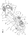
- . la figure 1 est une vue générale en perspective du bras d'autoguidage perfectionné engagé sur un rail directeur,
- . la figure 2 est une vue en perspective d'ensemble de l'avant en oblique côté droit avec brisure sur l'un des galets,
- . la figure 3 est une vue en perspective d'ensemble de l'avant en oblique côté gauche avec brisure sur l'un des galets,
- . la figure 4 est une vue en coupe transversale du couple de galets de guidage dans leur position de travail, c'est-à-dire en roulage sur le rail directeur,
- . les figures 5 et 6 sont des vues en coupe transversale du couple de galets de guidage illustrant la montée de la pièce d'inclinaison conformée en coin pour la libération des supports des galets de guidage,
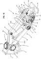
- . les figures 7, 8 et 9 sont des vues de profil illustrant les positions des éléments articulés dans les principales phases de la cinématique du bras,
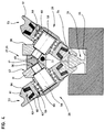
- . la figure 10 est une vue en perspective du côté gauche montrant en perspective une réalisation à pièce d'actionnement conique,
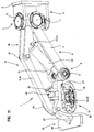
- . la figure 11 est une vue en perspective du côté droit montrant en perspective une réalisation à pièce d'écartement conique.
- . FIG. 1 is a general perspective view of the improved autoguiding arm engaged on a steering rail,
- . FIG. 2 is an overall perspective view of the front oblique on the right side with breaking on one of the rollers,
- . FIG. 3 is an overall perspective view of the oblique front on the left side with breaking on one of the rollers,
- . FIG. 4 is a cross-sectional view of the pair of guide rollers in their working position, that is to say when running on the steering rail,
- . FIGS. 5 and 6 are cross-sectional views of the pair of guide rollers illustrating the mounting of the inclined wedge piece for the release of the supports from the guide rollers,
- . FIGS. 7, 8 and 9 are side views illustrating the positions of the articulated elements in the main phases of the kinematics of the arm,
- . FIG. 10 is a perspective view on the left side showing in perspective an embodiment with a conical actuation part,
- . Figure 11 is a perspective view on the right side showing in perspective an embodiment with a conical spacer.
Le bras relevable perfectionné d'autoguidage selon l'invention constitue l'organe sensible directionnel le long d'un rail directeur d'un système de direction à guidage automatique.The improved self-guiding lifting arm according to the invention constitutes the directional sensitive member along a director rail of a steering system with automatic guidance.
Dans ce système de direction avec autoguidage, la fonction de capteur directionnel est assurée par un bras de guidage 1 monté articulé à la cardan sur un support d'extrémité 2 du châssis d'un véhicule routier constituant un centre d'articulation 3 formé d'un bloc-pivot 4 prolongé latéralement par un levier de commande directionnelle 5. Le bloc-pivot est monté pivotant autour d'un axe vertical 6 de direction et d'un axe horizontal 7 de basculement traversant le corps du bloc-pivot 4 sur lequel s'appuie le bras de guidage 1 pour ses mouvements verticaux d'abaissement et de levage.In this steering system with autoguiding, the directional sensor function is provided by a
Le bras de guidage 1 affecte la forme d'un corps rectiligne allongé en cadre articulé déformable constitué de plusieurs branches de longueur constante articulées à deux axes de pivotement de hauteur fixe et articulées entre elles dont une branche inférieure et une branche supérieure qui sont réunies entre elles, d'une part à l'avant par une branche d'extrémité et à l'arrière par une branche fixe dans le plan de relevage du bras. Le bras est formé d'abord d'une structure oblique inférieure de longueur constante 8 articulée à pivotement par son extrémité supérieure au bloc-pivot 4 par l'axe horizontal de basculement 7 et par son extrémité inférieure 9 au corps mécanique d'une tête de guidage 10 autour d'un axe inférieur de pivotement 11. La tête de guidage 10 forme la branche d'extrémité. Le cadre est formé ensuite de la branche supérieure sous la forme d'un bras articulé de liaison 12, destiné à constituer avec la structure oblique inférieure 8 et d'autres éléments dont la branche d'extrémité, le cadre d'extrémité déformable appelé ci-après ensemble articulé déformable 13 du type parallélogramme déformable.The
La structure oblique inférieure 8 est constituée de deux bielles obliques parallèles 14 et 15 alors que le bras de liaison 12 est formé d'un levier central 16 articulé à pivotement d'une part par un axe de pivotement supérieur 17 à une fourche supérieure 18 et d'autre part à un bloc mécanique de liaison 19 par un axe avant de pivotement 20. Le bloc mécanique de liaison 19 se prolonge à l'avant par un chasse-pierre 21 et s'étend à l'arrière jusqu'à l'axe inférieur de pivotement 11 qu'il porte et sur lequel s'articulent les bielles obliques 14 et 15. Cette unité constitue l'ensemble articulé 13 déformable sous l'action d'un vérin d'actionnement 22 monté articulé à chacune de ses extrémités. L'extrémité supérieure 23 du vérin 22 est articulée à pivotement sur la fourche supérieure 18 au voisinage de son extrémité libre par un axe de pivotement 24 et l'extrémité inférieure 25 du vérin 22 est articulée à pivotement par un axe 26 sur une pièce d'actionnement 27 d'un dispositif de commande en inclinaison pour la mise en prise ou la libération des galets de leur emprise sur le rail directeur.The
Le dispositif de commande en inclinaison des galets assure automatiquement à partir des mouvements de poussée ou de traction du vérin d'actionnement 22, par l'intermédiaire d'une pièce d'inclinaison 27 mobile par rapport à la tête de guidage, la libération ou le rapprochement des galets de guidage ainsi que la position autoverrouillée de fin de course.The device for controlling the inclination of the rollers ensures automatically from the pushing or pulling movements of the
On examinera maintenant plus en détail les moyens spécifiques utilisés.We will now examine in more detail the specific means used.
Le dispositif de commande en inclinaison se compose de la pièce d'inclinaison 27 articulée à pivotement à l'extrémité de la tige du vérin, soit séparément, soit de façon confondue avec l'axe inférieur de pivotement 11.The tilting control device is made up of the tilting
La tête de guidage est équipée de moyens de roulement formés de deux galets 28 et 29 disposés en "V" à pointe dirigée vers le bas, montés sur deux supports porte-galet 30 et 31 articulés à pivotement entre eux autour d'un axe inférieur ou supérieur 32 ou 33 par rapport à la pièce d'inclinaison 27.The guide head is fitted with rolling means formed by two
Selon la réalisation représentée, un des galets est fixe en inclinaison. Le rapprochement ou l'éloignement s'effectue par le mouvement d'un des galets par rapport à l'autre.According to the embodiment shown, one of the rollers is fixed in inclination. Reconciliation or the distance is effected by the movement of one of the rollers relative to the other.
En position de travail, les galets sont en prise sur les épaulements d'un rail directeur 34 qu'ils enserrent par un léger pincement. Ils sont maintenus, par exemple dans cette position, par un verrouillage apporté par le vérin d'actionnement maintenu légèrement en charge ou par le jeu d'inclinaison à faible pente de la pièce d'inclinaison ou tout autre moyen.In the working position, the rollers are engaged on the shoulders of a
Ils sont portés par deux supports porte-galet 30 et 31 de forme variable disposés de façon que la présentation des galets 28 et 29 soit en "V" à pointe dirigée vers le bas. Sur les faces extérieures de ces supports sont montés les axes de roulement des galets.They are carried by two roller carrier supports 30 and 31 of variable shape arranged so that the presentation of the
L'un des supports porte-galet ou les deux supports est ou sont actionné(s) en mouvements de libération ou de rapprochement des galets par le dispositif de commande et plus particulièrement par la pièce d'actionnement 27 qui est montée articulée sur l'extrémité de la tige du vérin d'actionnement 22.One of the roller support supports or the two supports is or are actuated in movement of release or reconciliation of the rollers by the control device and more particularly by the actuating
Différentes formes techniques de la pièce d'inclinaison 27 sont possibles. La fonction générale consiste à provoquer le pivotement d'au moins un support porte-galet par le seul déplacement relatif de cette pièce par rapport à l'autre support.Different technical forms of the tilting
Parmi les nombreuses variantes existantes pour la pièce d'inclinaison 27, on décrira ci-après deux formes de réalisation possibles : celle en coin et celle comportant une tige à extrémité conique.Among the many variants existing for the
Selon un premier mode de réalisation, les supports porte-galet 30 et 31 délimitent entre eux un volume récepteur pour la pièce d'inclinaison 27 dont le mouvement provoque l'actionnement en pivotement par rapport à leur axe commun de pivotement d'au moins un des deux supports porte-galet.According to a first embodiment, the roller carrier supports 30 and 31 delimit between them a receiving volume for the
Selon ce premier mode de réalisation, la pièce d'inclinaison est un sabot 35 à extrémité avant 36 conformée en coin.According to this first embodiment, the tilting piece is a shoe 35 with a
L'arrière de cette pièce d'actionnement présente une saillie sous la forme d'une platine latérale 37 par laquelle elle est articulée à l'extrémité de la tige du vérin. La partie basse 38 de cette pièce d'inclinaison de forme générale coudée est articulée à pivotement sur l'axe inférieur de pivotement 11. Dans le cas de la réalisation représentée, la face frontale de cette partie basse coudée sert de face de butée 39 contre un élément transversal pour permettre le basculement de relevage du bras.The rear of this actuating part has a projection in the form of a
Comme déjà indiqué, l'extrémité avant de la pièce d'inclinaison est réalisée en coin. Ce coin montre une surface latérale côté droit plane et verticale dans sa partie supérieure qui se prolonge vers le bas par un plan incliné 40 et une surface latérale gauche plane et inclinée 41 selon une pente appropriée. Les supports porte-galet 30 et 31 articulés entre eux à pivotement présentent chacun des faces latérales planes situées côté intérieur et disposées en regard. Le support de droite 30 est fixe en inclinaison et comporte une face latérale intérieure plane verticale puis inclinée alors que le support de gauche 31 est mobile en inclinaison par pivotement et présente une face latérale intérieure 42 plane et inclinée par exemple selon la même pente que la face latérale articulée 41 en regard de l'extrémité en coin 36.As already indicated, the front end of the tilting piece is made at a corner. This corner shows a flat right side vertical side surface in its upper part which is extended downwards by an
Les faces latérales en regard côté intérieur délimitent un volume récepteur dont au moins une paroi latérale est mobile en inclinaison.The side faces facing the interior side define a receiving volume, at least one side wall of which is movable in inclination.
Elles sont utilisées à cet effet comme rampe de poussée par le sabot de commande 35 constituant ici la pièce d'inclinaison dont la forme convergente de ces plans d'extrémité permet de convertir son mouvement de descente et d'avance en mouvement d'écartement des faces des parois latérales du volume récepteur et ainsi en mouvement de rapprochement des galets jusqu'à contact de prise avec les épaulements du rail puis effet de pincement et autoverrouillage.They are used for this purpose as a thrust ramp by the control shoe 35 constituting here the tilting piece whose convergent shape of these end planes makes it possible to convert its movement from descent and advance in movement of separation of the faces of the side walls of the receiving volume and thus in movement of approach of the rollers until engagement with the shoulders of the rail then pinching effect and self-locking.
Il convient de préciser ici que l'autoverrouillage peut résulter de l'état du vérin d'actionnement qu'on laisse en charge en fin de course de poussée ou bien d'une pente appropriée plus faible de la pièce d'inclinaison en coin ou tout autre moyen.It should be specified here that the self-locking can result from the state of the actuating cylinder which is left loaded at the end of the thrust stroke or else from an appropriate lower slope of the corner tilting piece or any other way.
Les figures 7, 8 et 9 permettent d'expliquer le fonctionnement général relatif aux mouvements du bras et des galets.Figures 7, 8 and 9 explain the general operation relating to the movements of the arm and rollers.
Le mouvement de relevage s'effectue en trois phases illustrées successivement par les figures ci-dessus qui peuvent être rapprochées des figures en coupe transversale.The lifting movement is carried out in three phases illustrated successively by the above figures which can be compared to the figures in cross section.
Le bras est à l'état initial rabattu avec les galets en prise sur le rail c'est-à-dire en serrant le rail avec un léger effet de pincement.The arm is in the initial state folded down with the rollers engaged on the rail, that is to say by tightening the rail with a slight pinching effect.
Dans cet état, le sabot 35 est en butée sur le fond du volume récepteur et son extrémité avant formant pièce de commande en inclinaison des galets est abaissée sous l'action du vérin d'actionnement et reste verrouillée dans cette position par le maintien d'une force apportée par le vérin légèrement en charge ou autre moyen. La pièce de commande en inclinaison force le galet de gauche en contrainte de pincement sur le rail pour lui même et par réaction mécanique pour le galet opposé.In this state, the shoe 35 is in abutment on the bottom of the receiving volume and its front end forming a control part in inclination of the rollers is lowered under the action of the actuating cylinder and remains locked in this position by maintaining a force provided by the slightly loaded cylinder or other means. The tilt control part forces the left roller under pinching stress on the rail for itself and by mechanical reaction for the opposite roller.
Le mouvement de relevage débute par la libération du galet. Cette libération à lieu par le simple basculement du sabot 35 en arrière autour de l'axe 11 sous l'effet du mouvement de traction du vérin. Au cours de ce mouvement, l'extrémité avant du sabot 35 remonte et libère ainsi le support porte-galet de gauche en mouvement.The lifting movement begins with the release of the roller. This release takes place by the simple tilting of the shoe 35 back about the
Le mouvement de basculement arrière du sabot 35 marque un arrêt par le contact de la face avant de l'extrémité basse de la partie coudée contre la surface de butée en regard.The rear tilting movement of the shoe 35 marks a stop by the contact of the front face of the lower end of the bent part against the facing abutment surface.
La poursuite par la continuation de la traction du vérin provoque la déformation de l'ensemble déformable 13 par rapprochement de la structure oblique inférieure 8 vers la partie supérieure du bras en même temps qu'une légère extension de celui-ci pour se retrouver dans la position représentée sur la figure 9 dans laquelle le bras est relevé et les galets libérés.The continuation by the continuation of the traction of the jack causes the deformation of the
On a réalisé ainsi un mécanisme automatique de relevage et commande des galets en inclinaison actionné uniquement par le vérin qui commande les différentes fonctions et leur succession.An automatic lifting and control mechanism for tilting rollers has thus been produced, actuated only by the jack which controls the various functions and their succession.
La traction du vérin provoque successivement et automatiquement la libération des galets et le soulèvement de l'ensemble.The traction of the jack successively and automatically causes the release of the rollers and the lifting of the assembly.
Inversement, la poussée du vérin rabaisse l'ensemble et verrouille les galets en inclinaison de prise sur le rail directeur.Conversely, the thrust of the jack lowers the assembly and locks the rollers in grip angle on the steering rail.
Selon le deuxième mode de réalisation représenté sur les figures 10 et 11, la pièce d'actionnement est une tige d'inclinaison 43 à extrémité conique dont le mouvement rectiligne d'avance ou de retrait est converti en mouvement d'écartement ou d'éloignement des supports porte-galet droit 44 et gauche 45.According to the second embodiment shown in FIGS. 10 and 11, the actuating part is an
Cette tige d'inclinaison 43 présente à environ mi-longueur une saillie diamétrale en collerette 46.This
La tige d'inclinaison 43 est articulée à pivotement à l'extrémité de la tige du vérin d'actionnement par une chape 47 traversée par l'axe inférieur de pivotement 11.The
Le bloc mécanique de liaison propre à cette variante, référencé 48, de l'ensemble articulé 13 sert toujours de support porte-galet 44 à inclinaison fixe. Il comporte sur son chant supérieur une articulation de pivotement 49 par laquelle le support porte-galet gauche 45 à inclinaison variable est articulé.The mechanical connection block specific to this variant, referenced 48, of the articulated
L'axe de pivotement 33 des porte-galets et donc des galets est déporté vers le haut au dessus de la pièce d'inclinaison 43 et le support porte-galet gauche 45 à inclinaison variable affecte une nouvelle forme technique du type pendulaire. L'exemple de réalisation représenté sur les figures 10 et 11 montre un bloc mécanique pivotant par le haut à face latérale extérieure oblique porte-galet et à extension supérieure traversée par l'axe de pivotement supérieur.The
Le corps du support porte-galet de gauche 45 comporte un volume récepteur qui procède du même principe selon lequel une conversion de mouvement de translation en mouvements de pivotement s'opère par la coopération d'une rampe conique ou simplement inclinée avec un élément mobile de commande en contact de poussée en vue de réaliser le rapprochement des supports porte-galet 44 et 45 et leur libération dans le sens contraire.The body of the
La collerette 46 constitue une structure de butée entre les faces avant 50 et arrière 51 d'un logement supérieur 52 qui détermine la course de commande de la pièce d'actionnement. La traction supplémentaire du vérin d'actionnement provoque le relevage par basculement de l'ensemble articulé 13.The
Les galets présentent un profil de gorge 53 imposant celui de l'épaulement 54 du rail directeur 34 qu'ils doivent suivre.The rollers have a
On peut, à cet effet, utiliser des profils de rail de forme triangulaire, ronde, en forme de coeur ou autre, dont la semelle 55 est montée sur un intercalaire insonorisant en fond de gorge 56 des éléments rectilignes préfabriqués du type caniveau 57 qui contiennent le rail.For this purpose, it is possible to use rail profiles of triangular, round, heart-shaped or other shape, the sole 55 of which is mounted on a sound-absorbing interlayer at the bottom of the
La constitution de chacun des galets est identique. Il s'agit d'une structure composite formée d'un axe de roulement ou axe-fusée 58 solidaire de chaque support porte-galet et sur lequel est monté à rotation un moyeu 59 par l'intermédiaire d'un roulement 60.The constitution of each of the rollers is identical. It is a composite structure formed by a rolling axle or
Sur la gorge périphérique du moyeu 59 est montée une couronne de roulement 61 par l'intermédiaire d'une garniture 62 de jante 63 en matière élastique, par exemple en élastomère, formée de deux rondelles coniques 64 et 65 épaisses disposées en "V" servant d'élément intermédiaire déformable permettant d'absorber par sa déformation les légers déplacements dus aux jeux fonctionnels, mais aussi le déport latéral dans les courbes.On the peripheral groove of the
Ces couronnes en matière élastique assurent en plus un complément d'isolation aux vibrations et l'isolation électrique.These elastic material crowns additionally provide additional vibration isolation and electrical insulation.
On a réalisé ainsi un ensemble de mise en prise de deux galets sur un rail qui est autoverrouillé par exemple par le maintien en charge du vérin d'actionnement ou par le jeu d'une rampe à faible pente pour la pièce d'inclinaison.There is thus produced a set of engagement of two rollers on a rail which is self-locked for example by maintaining the actuator in charge or by the play of a ramp with a slight slope for the tilting part.
Les formes et les fonctions techniques permettent au vérin d'actionnement de libérer automatiquement l'écartement des galets lors de la première phase du mouvement de levage et le rapprochement puis le pincement en fin de mouvement d'abaissement.The shapes and the technical functions allow the actuating cylinder to automatically release the spacing of the rollers during the first phase of the lifting movement and the reconciliation then the clamping at the end of the lowering movement.
Le support chasse-pierre 21 placé devant les galets pour les protéger est formé d'un bras incurvé 66 terminé par une platine transversale horizontale 67 disposée juste au-dessus du rail. Il s'agit d'un support faisant partie intégrante de l'ensemble articulé déformable. Il s'escamote avec lui par relevage de l'ensemble.The stone-chasing
Claims (15)
- Raisable arm for automatically guiding a land vehicle along a guide rail and comprising at its front end two guide rollers (28, 29) which are inclined in a V shape with a downwardly directed point, each guide roller engaging via its groove on one of the shoulders of the guide rail so as to form a directional control member comprising a movable arm (1) which is operatively connected to the vehicle guiding assembly and is articulated on the vehicle chassis by two intersecting axles, one (6) vertical and the other (7) horizontal, the axles being assembled to form an articulation centre (3), the raisable movable arm being actuated for raising and lowering movements via an actuating cylinder (22) articulated between the articulation centre (3) and a bottom part of the arm body, the arm (1) having a support means which is movable under the effect of the actuating cylinder (22) and comprises at its end the pair of guide rollers (28, 29) carried by roller-carrier supports (30, 31), and at least one of these rollers (28, 29) swivelling in an inclined manner relative to the other, the raisable arm comprising a device controlling the rollers (28, 29) such that they move towards one another and releasing them such that they move apart.
- Arm according to Claim 1, characterized in that the movable support means is a structure which is articulated to form a frame which can be deformed in a given vertical plane under the effect of the actuating cylinder (22) and is formed by three branches which are articulated relative to one another and comprise a lower branch, an end branch and an upper branch, the lower and upper branches being connected to two support articulations which swivel about two horizontal swivel pins of constant height during the raising movement, the end branch comprising the guide roller pair.
- Arm according to Claim 1 or 2, characterized in that one of the roller-carrier supports (30, 31) is fixed and the other can move in an inclined manner relative to the adjacent roller-carrier support under the effect of an inclination part (27) actuated by the cylinder (22).
- Arm according to Claim 1 or 2, characterized in that the control device is actuated by the cylinder (22).
- Arm according to any one of the preceding claims, characterized in that the fixed-inclination roller-carrier support (30) is the end branch of the deformable articulated structure.
- Arm according to any one of the preceding claims, characterized in that the swivel pin of the roller-carrier supports (30, 31) is located below the inclination part (27).
- Arm according to Claim 6, characterized in that the inclination part (27) is a tilting shoe (35) which is connected on the one hand to the cylinder rod and on the other to the lower swivel pin and whose end, with a downward movement, actuates at least one of the inclined roller-carrier supports (30, 31) for moving together then squeezing the rollers (28, 29) and, as it rises, releases at least one of the roller-carrier supports.
- Arm according to Claim 7, characterized in that the end (36) of the inclination part is shaped as a wedge of which one of the slopes is inclined and co-operates with the rear face of the roller-carrier support (31) which can move in inclined manner so as to cause the rollers to move together by its downward movement and release these rollers by its upward movement.
- Arm according to any one of the preceding claims, characterized in that the inclination part (27) is held locked in the bottom position.
- Arm according to Claim 9, characterized in that the cylinder remains under load when the inclination part (27) is in the bottom position holding the rollers (28, 29) close together.
- Arm according to Claim 9, characterized in that the inclined slope of the inclination part is shallow.
- Arm according to any one of Claims 1 to 5, characterized in that the roller-carrier support swivel pin is located above the inclination part (27).
- Arm according to the preceding claim, characterized in that the inclination part (27) is articulated on the upper swivel pin and takes the form of rod with a conical end of which the cross-section is delimited by a front stop and a rear stop.
- Arm according to Claim 1, characterized in that the rollers (28, 29) are formed by a bearing ring (61) mounted on the hub by means of a mounting (62) with a rim (63) made of resilient insulating material.
- Arm according to the preceding claim, characterized in that the mounting (62) with a rim (63) has a truncated V-shaped profile formed by the juxtaposition of two conical washers.
Applications Claiming Priority (3)
| Application Number | Priority Date | Filing Date | Title |
|---|---|---|---|
| FR9400732A FR2715119B1 (en) | 1994-01-20 | 1994-01-20 | Improved autoguiding arm of a road vehicle along a steering rail. |
| FR9400732 | 1994-01-20 | ||
| PCT/FR1995/000057 WO1995019904A1 (en) | 1994-01-20 | 1995-01-19 | Improved arm for automatically guiding a road vehicle along a guide rail |
Publications (2)
| Publication Number | Publication Date |
|---|---|
| EP0739286A1 EP0739286A1 (en) | 1996-10-30 |
| EP0739286B1 true EP0739286B1 (en) | 1997-07-23 |
Family
ID=9459335
Family Applications (1)
| Application Number | Title | Priority Date | Filing Date |
|---|---|---|---|
| EP95907048A Expired - Lifetime EP0739286B1 (en) | 1994-01-20 | 1995-01-19 | Improved arm for automatically guiding a road vehicle along a guide rail |
Country Status (12)
| Country | Link |
|---|---|
| US (1) | US5704295A (en) |
| EP (1) | EP0739286B1 (en) |
| KR (1) | KR100358377B1 (en) |
| CN (1) | CN1048217C (en) |
| AT (1) | ATE155751T1 (en) |
| DE (1) | DE69500464T2 (en) |
| DK (1) | DK0739286T3 (en) |
| ES (1) | ES2105891T3 (en) |
| FR (1) | FR2715119B1 (en) |
| RU (1) | RU2124996C1 (en) |
| UA (1) | UA34490C2 (en) |
| WO (1) | WO1995019904A1 (en) |
Cited By (2)
| Publication number | Priority date | Publication date | Assignee | Title |
|---|---|---|---|---|
| DE102005038240B3 (en) * | 2005-08-12 | 2006-12-21 | Siemens Ag | Tracking device for a vehicle with rubber tires has a guard rail and guide wheels to maintain contact with the vehicle's steering device |
| DE102006028689B4 (en) * | 2006-06-22 | 2009-12-17 | Siemens Ag | Device for tracking a road vehicle |
Families Citing this family (27)
| Publication number | Priority date | Publication date | Assignee | Title |
|---|---|---|---|---|
| FR2735728B1 (en) * | 1995-06-23 | 1997-08-08 | Lohr Ind | POWER SUPPLY AND GUIDANCE ASSEMBLY ALONG A GROUND RAIL FOR VEHICLE ON WHEELS |
| FR2759340B1 (en) * | 1997-02-11 | 1999-04-09 | Lohr Ind | GUIDANCE SYSTEM ALONG AT LEAST ONE GROUND RAIL FOR AN AXLE OF A ROAD VEHICLE |
| FR2778161B1 (en) * | 1998-04-30 | 2000-07-21 | Lohr Ind | BIDIRECTIONAL GUIDANCE ASSEMBLY ALONG A RAIL ALLOWING A LATERAL OFFSET FOR A ROAD AXLE |
| EP1047587A4 (en) * | 1998-10-02 | 2002-07-31 | Daimlerchrysler Rail Systems | Guide wheel assembly |
| US6477964B1 (en) * | 1999-10-15 | 2002-11-12 | Tygard Machine And Manufacturing Company | Guide system for a forklift |
| US6374948B1 (en) * | 1999-10-28 | 2002-04-23 | Portec Rail Products, Inc. | Rail lubricator |
| NL1013747C2 (en) * | 1999-12-03 | 2001-06-25 | Stertil Bv | Vehicle blocking device. |
| GB0203296D0 (en) * | 2002-02-12 | 2002-03-27 | Glaxo Group Ltd | Novel composition |
| FR2846917B1 (en) * | 2002-11-08 | 2005-01-07 | Lohr Ind | PERMANENT GROUNDING CONTROL DEVICE FOR ELECTRICAL TIRE AND AUTOGUIDE COMMERCIAL TRANSPORT VEHICLE |
| FR2865986B1 (en) * | 2004-02-09 | 2007-04-13 | Lohr Ind | INCLINE DUCTING GUIDE GALET FOR A GUIDE ASSEMBLY ALONG A RAIL. |
| FR2909061B1 (en) * | 2006-11-29 | 2009-01-09 | Lohr Ind | DEVICE FOR DETECTING THE RISK OF DERAILING AND EVACUATION OF DEBRIS OR OBJECTS ON THE RAILWAY GUIDE OF A VEHICLE. |
| FR2910423B1 (en) * | 2006-12-22 | 2009-02-20 | Lohr Ind | ANTI-EXTRACTION SECURITY DEVICE FOR A GUIDE ASSEMBLY BY TWO INCLINED ROLLERS RUNNING ON A RAIL. |
| FR2916411B1 (en) * | 2007-05-25 | 2009-07-24 | Lohr Ind | BIDIRECTIONAL GUIDE SYSTEM WITH LATERAL DEBATMENT LIMITATION, FOR A ROAD AXIAL GUIDED BY A GROUND RAIL. |
| FR2920448B1 (en) * | 2007-08-29 | 2013-07-05 | Lohr Ind | PREFABRICAL TRACK MODULE FOR URBAN AUTOGUIDE PNEUMATIC TRANSPORT VEHICLE |
| PL2459427T3 (en) * | 2009-07-28 | 2013-11-29 | Siemens Sas | Method and device for detecting the derailment of a guided vehicle |
| FR2981904B1 (en) * | 2011-10-28 | 2013-11-01 | Lohr Ind | SYSTEM FOR DYNAMICALLY CONTROLLING THE ROLLING OF THE GUIDE RAIL (S) FOR A GUIDE ASSEMBLY OF A VEHICLE ALONG AT LEAST ONE RAIL. |
| FR2982827B1 (en) * | 2011-11-22 | 2013-11-29 | Lohr Ind | REENGAGING ANTI-EXTRACTION SECURITY DEVICE FOR A ROLLING ROLLER GUIDE ASSEMBLY ON A GUIDE RAIL |
| EP2676863A1 (en) * | 2012-06-20 | 2013-12-25 | Siemens SAS | Method and devices for protecting against a loss of steering in a guided vehicle |
| FR3014400B1 (en) | 2013-12-11 | 2016-02-05 | Alstom Transport Sa | LAND VEHICLE GUIDE COMPRISING A DEVICE FOR MANAGING A DERAILMENT OF THE VEHICLE, AND METHOD FOR MANAGING THE DERAILMENT THEREOF |
| CN105621039A (en) * | 2015-12-28 | 2016-06-01 | 同方威视技术股份有限公司 | Vehicle traction device and radiation imaging inspection system |
| IT201600082789A1 (en) * | 2016-08-05 | 2018-02-05 | Tesmec Spa | AUTOMATIC RAILWAY POSITIONING SYSTEM |
| CN107196251A (en) * | 2017-07-19 | 2017-09-22 | 成都市新筑路桥机械股份有限公司 | A kind of passive sliding formula crosses line Biodge device |
| US10533609B2 (en) * | 2017-07-19 | 2020-01-14 | Rge Motor Direct Inc. | Roller bearing |
| DE202018104230U1 (en) * | 2018-07-23 | 2019-10-28 | Losyco Gmbh | Rail wheelset and carriage |
| CN109050385B (en) * | 2018-08-14 | 2020-06-05 | 惠龙易通国际物流股份有限公司 | Tank wagon and fixing base |
| FR3096950B1 (en) * | 2019-06-05 | 2022-07-22 | Newtl | Roller flange wear monitoring device |
| DE102022201683A1 (en) | 2022-02-17 | 2023-08-17 | Nt Innovation Ohg | Rail vehicle, in particular two-way vehicle set up for changing lanes and the corresponding system, method and use |
Family Cites Families (17)
| Publication number | Priority date | Publication date | Assignee | Title |
|---|---|---|---|---|
| US128597A (en) * | 1872-07-02 | Improvement in railways | ||
| FR514718A (en) * | 1920-04-29 | 1921-03-17 | Louis Georges Edouard Lefranc | Device intended to automatically ensure the steering of motor or towed vehicles and track system for its application |
| DE1161157B (en) * | 1960-04-09 | 1964-01-09 | Heiner Kuch | Wheel steering for vehicles with guardrail or hand control |
| DE1128765B (en) * | 1960-04-09 | 1962-04-26 | Heiner Kuch | Wheel steering for vehicles with guardrail or hand control |
| US3180280A (en) * | 1963-08-28 | 1965-04-27 | Kuch Heiner | Vehicle and guide rail therefor |
| US3707125A (en) * | 1968-05-08 | 1972-12-26 | Gen Am Transport | Railway trucks |
| US3866484A (en) * | 1970-09-03 | 1975-02-18 | R H Dreshman & Sons Inc | Rack and pinion actuated machine |
| FR2129052A5 (en) * | 1971-03-12 | 1972-10-27 | Materiel De Voirie | |
| US3730105A (en) * | 1971-10-29 | 1973-05-01 | Holley Engin Co Inc | Convertible railhighway vehicle |
| US3942449A (en) * | 1972-06-01 | 1976-03-09 | Ltv Aerospace Corporation | Transportation system |
| SE402243B (en) * | 1975-06-11 | 1978-06-26 | Storm Anders Georg | VEHICLES FOR GRAINING ON SAVEL ROADS AND RAILWAY SAVINGS |
| US4416456A (en) * | 1978-12-08 | 1983-11-22 | Australasian Training Aids Pty. Ltd. | Trolleys for target ranges |
| LU83276A1 (en) * | 1981-04-02 | 1983-03-24 | Constr Ferroviaires & Metalliq | AUTOMATIC GUIDANCE SYSTEM FOR A VEHICLE WITH PNEUMATIC TIRE WHEELS |
| CN1009069B (en) * | 1986-07-17 | 1990-08-08 | 铁路和金属建造股份有限公司 | The homing system of the rapid vehicle of pneumatic tyre steering wheel is housed |
| US5024163A (en) * | 1988-09-02 | 1991-06-18 | Erwin Lenz | Derailment resisting, tractive power railway system |
| US5156639A (en) * | 1991-11-18 | 1992-10-20 | Deere & Company | Railway maintenance vehicle |
| FR2705636B1 (en) * | 1993-05-26 | 1995-07-07 | Lohr Ind | Directional guide assembly for a road vehicle along a rail. |
-
1994
- 1994-01-20 FR FR9400732A patent/FR2715119B1/en not_active Expired - Lifetime
-
1995
- 1995-01-19 EP EP95907048A patent/EP0739286B1/en not_active Expired - Lifetime
- 1995-01-19 DK DK95907048.3T patent/DK0739286T3/en active
- 1995-01-19 DE DE69500464T patent/DE69500464T2/en not_active Expired - Lifetime
- 1995-01-19 CN CN95191280A patent/CN1048217C/en not_active Expired - Fee Related
- 1995-01-19 RU RU96115943A patent/RU2124996C1/en not_active IP Right Cessation
- 1995-01-19 ES ES95907048T patent/ES2105891T3/en not_active Expired - Lifetime
- 1995-01-19 WO PCT/FR1995/000057 patent/WO1995019904A1/en active IP Right Grant
- 1995-01-19 US US08/676,337 patent/US5704295A/en not_active Expired - Lifetime
- 1995-01-19 AT AT95907048T patent/ATE155751T1/en not_active IP Right Cessation
- 1995-01-19 UA UA96083310A patent/UA34490C2/en unknown
- 1995-01-19 KR KR1019960703878A patent/KR100358377B1/en not_active IP Right Cessation
Cited By (2)
| Publication number | Priority date | Publication date | Assignee | Title |
|---|---|---|---|---|
| DE102005038240B3 (en) * | 2005-08-12 | 2006-12-21 | Siemens Ag | Tracking device for a vehicle with rubber tires has a guard rail and guide wheels to maintain contact with the vehicle's steering device |
| DE102006028689B4 (en) * | 2006-06-22 | 2009-12-17 | Siemens Ag | Device for tracking a road vehicle |
Also Published As
| Publication number | Publication date |
|---|---|
| ATE155751T1 (en) | 1997-08-15 |
| US5704295A (en) | 1998-01-06 |
| CN1048217C (en) | 2000-01-12 |
| DE69500464T2 (en) | 1998-02-19 |
| UA34490C2 (en) | 2001-03-15 |
| WO1995019904A1 (en) | 1995-07-27 |
| ES2105891T3 (en) | 1997-10-16 |
| DE69500464D1 (en) | 1997-09-04 |
| DK0739286T3 (en) | 1998-02-16 |
| FR2715119B1 (en) | 1996-02-23 |
| FR2715119A1 (en) | 1995-07-21 |
| CN1138843A (en) | 1996-12-25 |
| KR100358377B1 (en) | 2003-03-04 |
| RU2124996C1 (en) | 1999-01-20 |
| EP0739286A1 (en) | 1996-10-30 |
Similar Documents
| Publication | Publication Date | Title |
|---|---|---|
| EP0739286B1 (en) | Improved arm for automatically guiding a road vehicle along a guide rail | |
| FR2471869A1 (en) | HANDLING DEVICE FOR FACILITATING CHANGES OF VEHICLE WHEELS, ESPECIALLY AGRICULTURAL TRACTORS OR TRUCKS | |
| FR2759340A1 (en) | GUIDANCE SYSTEM ALONG AT LEAST ONE GROUND RAIL FOR AN AXLE OF A ROAD VEHICLE | |
| WO1997020114A1 (en) | Movable covering device, particularly for swimming pools | |
| EP1073576B1 (en) | Two-way guiding assembly along a rail for a road axle lateral offset | |
| EP0062370B1 (en) | Automatic guiding system for a vehicle fitted with pneumatic tyres | |
| FR2807974A1 (en) | CHASSIS FOR LIFT PLATFORM AND SCISSOR LIFT PLATFORM EQUIPPED WITH SUCH A CHASSIS | |
| EP1476343A1 (en) | Hand truck materials handling device | |
| FR2981311A1 (en) | TOWING APPARATUS FOR A MOTOR VEHICLE | |
| FR2899196A1 (en) | TRACTOR FOR TRANSPORTING MOBILE TRANSPORT RECEPTACLES. | |
| EP0100926A1 (en) | Material handling vehicle with an orientable arm and incorporated stabiliser frame | |
| FR2567083A1 (en) | Loading and transport vehicle for airport | |
| EP0178998B1 (en) | Jack-type lifting device for a vehicle | |
| EP0589772B1 (en) | Plate apparatus for mechanical testing of soils and vehicle equipped with this apparatus | |
| FR2545763A1 (en) | Improvement to vehicles capable of driving either on a road or on a railway track | |
| FR2759049A1 (en) | Shopping trolley | |
| FR2516022A1 (en) | TROLLEY TROLLEY | |
| EP1495994B1 (en) | Mobile refuse collecter | |
| FR2491005A1 (en) | Tractor for road or rail use - has road wheel on rail allowing eccentric loading of jib arm | |
| EP0029393B1 (en) | Loading device of the platform-lift type retractable inside a vehicle | |
| FR2551408A1 (en) | Recovery trolley for road vehicle | |
| EP0374194B1 (en) | Systeme for driving carriages on a rail and process for operating same | |
| EP1874670A2 (en) | Lifting appliance or jack for vehicle | |
| CA1302335C (en) | Drive system for trolleys along a rail, and process for its application | |
| FR2585295A1 (en) | Towable vehicle comprising an extensible hitching device |
Legal Events
| Date | Code | Title | Description |
|---|---|---|---|
| PUAI | Public reference made under article 153(3) epc to a published international application that has entered the european phase |
Free format text: ORIGINAL CODE: 0009012 |
|
| 17P | Request for examination filed |
Effective date: 19960801 |
|
| AK | Designated contracting states |
Kind code of ref document: A1 Designated state(s): AT BE CH DE DK ES GB GR IE IT LI LU MC NL PT SE |
|
| GRAG | Despatch of communication of intention to grant |
Free format text: ORIGINAL CODE: EPIDOS AGRA |
|
| GRAG | Despatch of communication of intention to grant |
Free format text: ORIGINAL CODE: EPIDOS AGRA |
|
| 17Q | First examination report despatched |
Effective date: 19961119 |
|
| GRAH | Despatch of communication of intention to grant a patent |
Free format text: ORIGINAL CODE: EPIDOS IGRA |
|
| GRAH | Despatch of communication of intention to grant a patent |
Free format text: ORIGINAL CODE: EPIDOS IGRA |
|
| GRAA | (expected) grant |
Free format text: ORIGINAL CODE: 0009210 |
|
| AK | Designated contracting states |
Kind code of ref document: B1 Designated state(s): AT BE CH DE DK ES GB GR IE IT LI LU MC NL PT SE |
|
| PG25 | Lapsed in a contracting state [announced via postgrant information from national office to epo] |
Ref country code: GR Free format text: LAPSE BECAUSE OF FAILURE TO SUBMIT A TRANSLATION OF THE DESCRIPTION OR TO PAY THE FEE WITHIN THE PRESCRIBED TIME-LIMIT Effective date: 19970723 |
|
| REF | Corresponds to: |
Ref document number: 155751 Country of ref document: AT Date of ref document: 19970815 Kind code of ref document: T |
|
| REG | Reference to a national code |
Ref country code: CH Ref legal event code: EP |
|
| REF | Corresponds to: |
Ref document number: 69500464 Country of ref document: DE Date of ref document: 19970904 |
|
| ITF | It: translation for a ep patent filed |
Owner name: MARIETTI E GISLON S.R.L. |
|
| REG | Reference to a national code |
Ref country code: ES Ref legal event code: FG2A Ref document number: 2105891 Country of ref document: ES Kind code of ref document: T3 |
|
| GBT | Gb: translation of ep patent filed (gb section 77(6)(a)/1977) |
Effective date: 19970929 |
|
| REG | Reference to a national code |
Ref country code: PT Ref legal event code: SC4A Free format text: AVAILABILITY OF NATIONAL TRANSLATION Effective date: 19970929 |
|
| PG25 | Lapsed in a contracting state [announced via postgrant information from national office to epo] |
Ref country code: LU Free format text: LAPSE BECAUSE OF NON-PAYMENT OF DUE FEES Effective date: 19980119 |
|
| REG | Reference to a national code |
Ref country code: DK Ref legal event code: T3 |
|
| PG25 | Lapsed in a contracting state [announced via postgrant information from national office to epo] |
Ref country code: IE Free format text: LAPSE BECAUSE OF NON-PAYMENT OF DUE FEES Effective date: 19980330 |
|
| REG | Reference to a national code |
Ref country code: IE Ref legal event code: FD4D Ref document number: 75337 Country of ref document: IE |
|
| PLBE | No opposition filed within time limit |
Free format text: ORIGINAL CODE: 0009261 |
|
| STAA | Information on the status of an ep patent application or granted ep patent |
Free format text: STATUS: NO OPPOSITION FILED WITHIN TIME LIMIT |
|
| 26N | No opposition filed | ||
| PG25 | Lapsed in a contracting state [announced via postgrant information from national office to epo] |
Ref country code: MC Free format text: LAPSE BECAUSE OF NON-PAYMENT OF DUE FEES Effective date: 19980731 |
|
| REG | Reference to a national code |
Ref country code: GB Ref legal event code: IF02 |
|
| PGFP | Annual fee paid to national office [announced via postgrant information from national office to epo] |
Ref country code: SE Payment date: 20030129 Year of fee payment: 9 |
|
| PGFP | Annual fee paid to national office [announced via postgrant information from national office to epo] |
Ref country code: NL Payment date: 20030131 Year of fee payment: 9 Ref country code: DK Payment date: 20030131 Year of fee payment: 9 |
|
| PG25 | Lapsed in a contracting state [announced via postgrant information from national office to epo] |
Ref country code: SE Free format text: LAPSE BECAUSE OF NON-PAYMENT OF DUE FEES Effective date: 20040120 |
|
| PG25 | Lapsed in a contracting state [announced via postgrant information from national office to epo] |
Ref country code: DK Free format text: LAPSE BECAUSE OF NON-PAYMENT OF DUE FEES Effective date: 20040202 |
|
| PG25 | Lapsed in a contracting state [announced via postgrant information from national office to epo] |
Ref country code: NL Free format text: LAPSE BECAUSE OF NON-PAYMENT OF DUE FEES Effective date: 20040801 |
|
| EUG | Se: european patent has lapsed | ||
| REG | Reference to a national code |
Ref country code: DK Ref legal event code: EBP |
|
| NLV4 | Nl: lapsed or anulled due to non-payment of the annual fee |
Effective date: 20040801 |
|
| PGFP | Annual fee paid to national office [announced via postgrant information from national office to epo] |
Ref country code: PT Payment date: 20050111 Year of fee payment: 11 |
|
| PGFP | Annual fee paid to national office [announced via postgrant information from national office to epo] |
Ref country code: AT Payment date: 20050114 Year of fee payment: 11 |
|
| PG25 | Lapsed in a contracting state [announced via postgrant information from national office to epo] |
Ref country code: AT Free format text: LAPSE BECAUSE OF NON-PAYMENT OF DUE FEES Effective date: 20060119 |
|
| PG25 | Lapsed in a contracting state [announced via postgrant information from national office to epo] |
Ref country code: PT Free format text: LAPSE BECAUSE OF NON-PAYMENT OF DUE FEES Effective date: 20060719 |
|
| REG | Reference to a national code |
Ref country code: PT Ref legal event code: MM4A Effective date: 20060719 |
|
| PGFP | Annual fee paid to national office [announced via postgrant information from national office to epo] |
Ref country code: IT Payment date: 20120126 Year of fee payment: 18 |
|
| PGFP | Annual fee paid to national office [announced via postgrant information from national office to epo] |
Ref country code: CH Payment date: 20130124 Year of fee payment: 19 Ref country code: DE Payment date: 20130126 Year of fee payment: 19 Ref country code: ES Payment date: 20130222 Year of fee payment: 19 Ref country code: GB Payment date: 20130218 Year of fee payment: 19 |
|
| PGFP | Annual fee paid to national office [announced via postgrant information from national office to epo] |
Ref country code: BE Payment date: 20130124 Year of fee payment: 19 |
|
| BERE | Be: lapsed |
Owner name: *LOHR INDUSTRIE Effective date: 20140131 |
|
| REG | Reference to a national code |
Ref country code: DE Ref legal event code: R119 Ref document number: 69500464 Country of ref document: DE |
|
| REG | Reference to a national code |
Ref country code: CH Ref legal event code: PL |
|
| GBPC | Gb: european patent ceased through non-payment of renewal fee |
Effective date: 20140119 |
|
| REG | Reference to a national code |
Ref country code: DE Ref legal event code: R119 Ref document number: 69500464 Country of ref document: DE Effective date: 20140801 |
|
| PG25 | Lapsed in a contracting state [announced via postgrant information from national office to epo] |
Ref country code: CH Free format text: LAPSE BECAUSE OF NON-PAYMENT OF DUE FEES Effective date: 20140131 Ref country code: DE Free format text: LAPSE BECAUSE OF NON-PAYMENT OF DUE FEES Effective date: 20140801 Ref country code: LI Free format text: LAPSE BECAUSE OF NON-PAYMENT OF DUE FEES Effective date: 20140131 |
|
| PG25 | Lapsed in a contracting state [announced via postgrant information from national office to epo] |
Ref country code: GB Free format text: LAPSE BECAUSE OF NON-PAYMENT OF DUE FEES Effective date: 20140119 |
|
| PG25 | Lapsed in a contracting state [announced via postgrant information from national office to epo] |
Ref country code: BE Free format text: LAPSE BECAUSE OF NON-PAYMENT OF DUE FEES Effective date: 20140131 |
|
| REG | Reference to a national code |
Ref country code: ES Ref legal event code: FD2A Effective date: 20150330 |
|
| PG25 | Lapsed in a contracting state [announced via postgrant information from national office to epo] |
Ref country code: ES Free format text: LAPSE BECAUSE OF NON-PAYMENT OF DUE FEES Effective date: 20140120 |
|
| PG25 | Lapsed in a contracting state [announced via postgrant information from national office to epo] |
Ref country code: IT Free format text: LAPSE BECAUSE OF NON-PAYMENT OF DUE FEES Effective date: 20140119 |