EP0738672B1 - Vorrichtung zum Vereinzeln von übereinander verkreuzten Bügelhaken - Google Patents
Vorrichtung zum Vereinzeln von übereinander verkreuzten Bügelhaken Download PDFInfo
- Publication number
- EP0738672B1 EP0738672B1 EP96100825A EP96100825A EP0738672B1 EP 0738672 B1 EP0738672 B1 EP 0738672B1 EP 96100825 A EP96100825 A EP 96100825A EP 96100825 A EP96100825 A EP 96100825A EP 0738672 B1 EP0738672 B1 EP 0738672B1
- Authority
- EP
- European Patent Office
- Prior art keywords
- pins
- hooks
- shaft
- separating
- shafts
- Prior art date
- Legal status (The legal status is an assumption and is not a legal conclusion. Google has not performed a legal analysis and makes no representation as to the accuracy of the status listed.)
- Expired - Lifetime
Links
- 239000007787 solid Substances 0.000 claims description 3
- 238000005266 casting Methods 0.000 claims 1
- 239000012858 resilient material Substances 0.000 claims 1
- 238000000926 separation method Methods 0.000 description 6
- 210000003739 neck Anatomy 0.000 description 2
- 244000089486 Phragmites australis subsp australis Species 0.000 description 1
- 230000002146 bilateral effect Effects 0.000 description 1
- 230000006835 compression Effects 0.000 description 1
- 238000007906 compression Methods 0.000 description 1
- 238000002955 isolation Methods 0.000 description 1
- 239000000463 material Substances 0.000 description 1
- 238000009987 spinning Methods 0.000 description 1
Images



Classifications
-
- B—PERFORMING OPERATIONS; TRANSPORTING
- B65—CONVEYING; PACKING; STORING; HANDLING THIN OR FILAMENTARY MATERIAL
- B65G—TRANSPORT OR STORAGE DEVICES, e.g. CONVEYORS FOR LOADING OR TIPPING, SHOP CONVEYOR SYSTEMS OR PNEUMATIC TUBE CONVEYORS
- B65G47/00—Article or material-handling devices associated with conveyors; Methods employing such devices
- B65G47/22—Devices influencing the relative position or the attitude of articles during transit by conveyors
- B65G47/26—Devices influencing the relative position or the attitude of articles during transit by conveyors arranging the articles, e.g. varying spacing between individual articles
- B65G47/28—Devices influencing the relative position or the attitude of articles during transit by conveyors arranging the articles, e.g. varying spacing between individual articles during transit by a single conveyor
-
- B—PERFORMING OPERATIONS; TRANSPORTING
- B65—CONVEYING; PACKING; STORING; HANDLING THIN OR FILAMENTARY MATERIAL
- B65G—TRANSPORT OR STORAGE DEVICES, e.g. CONVEYORS FOR LOADING OR TIPPING, SHOP CONVEYOR SYSTEMS OR PNEUMATIC TUBE CONVEYORS
- B65G33/00—Screw or rotary spiral conveyors
- B65G33/02—Screw or rotary spiral conveyors for articles
-
- B—PERFORMING OPERATIONS; TRANSPORTING
- B65—CONVEYING; PACKING; STORING; HANDLING THIN OR FILAMENTARY MATERIAL
- B65G—TRANSPORT OR STORAGE DEVICES, e.g. CONVEYORS FOR LOADING OR TIPPING, SHOP CONVEYOR SYSTEMS OR PNEUMATIC TUBE CONVEYORS
- B65G2201/00—Indexing codes relating to handling devices, e.g. conveyors, characterised by the type of product or load being conveyed or handled
- B65G2201/02—Articles
- B65G2201/0229—Clothes, clothes hangers
Definitions
- the invention relates to a device for separating one above the other crossed hooks hanging on a bracket or the like transported goods, with a rotating, in essentially cylindrical, at least partially hollow body, which the hooks grip and from which they are transported, whereby the body a radially outward, between two hooks cross-separating device.
- a generic device is disclosed in WO 93/03985.
- the hanger hooks are passed onto a rotating tube that a separating device pointing radially outwards in the form a separating knife bar.
- Below the spinning Rohres are arranged two separation fingers, which are independent of each other are driven to slide back and forth.
- the dividing fingers are controlled alternately and are so close to each other in parallel arranged that only one bow hook neck between them fits.
- By controlling the separating fingers accordingly two crossed hooks to the separating device positioned.
- the dividing knife bar running around the tube then engages between the two hooks and lifts the upper one Bow hooks across the bottom, separating them.
- By controlling the separating fingers appropriately, the two then separate stirrup transported.
- EP 0 346 991 A1 discloses a separating device for Bow hooks that are conveyed on a spindle.
- the separating device is formed by disc-shaped dividers, which are attached to the spindle.
- the dividers are simply coiled so that you first have individual separating fingers diametrically opposite two separating fingers.
- the slope of the spiral disc is such that the distance between the two Separating fingers roughly corresponds to the wire diameter of the hook, so that only one hanger hook from the separating device can be taken.
- JP 62-235 120 (A) discloses a separating device in distributed over the circumference of a spindle in the axial direction staggered hooks are provided between individual Grab hooks and can separate them.
- the problem is solved in that the separating device a plurality of arranged in parallel Has pins that resiliently mounted inside the body and protrude from the body through elongated holes.
- This training makes it possible, on the one hand, to do more than to separate two crossed hooks, because of the parallel arrangement of the pins several in a row Separation processes can be carried out. Instead of one is a steady movement in the Separation device possible and the separation is independent of temples approaching in time. Naturally brackets can also be separated, the hooks of which are not are crossed.
- the pins are preferably mounted on an axially displaceable, rotatable shaft attached within the hollow body. In which in particular, each pin is attached to a separate shaft.
- a particularly space-saving arrangement can be achieved when the individual waves are nested and in symmetrical Arrangement opposite a radial line in mirror image in the hollow body are arranged.
- the axial movability of the individual shaft arrangements is then opposed. This results in a different direction of movement of the pins, so that evasion when separating for each type of crossed arms is possible.
- pins are provided of which two on a hollow shaft and two on each a full wave are arranged and each a full wave in one Hollow shaft runs. This optimizes the space required.
- the pins are preferably screwed into the Shafts attached. Furthermore, they can preferably be cranked Have point with which the hanger hooks securely from below can be taken and by which is prevented that the Lifting out the upper bracket that slips over the pin.
- the distance between two pins corresponds approximately to the diameter a hook, so that only one hook is always safely guided becomes.
- the body is preferably a spindle, which in turn is bilateral is associated with waves.
- the pins are preferably axially and radially offset. There is a combined axial and radial movement for each pin executable. This makes it particularly quiet and even The brackets can be unbundled.
- the pins are each in an axially sprung bolt, with at least four bolts are provided inside the hollow body.
- the pins in the hollow body in an elastic Mass for example rubber or the like to be shed.
- the Mobility can then be set according to the material selection become.
- the elasticity of the mass must be sufficient to spring the pins back to their original position.
- the pins can preferably each radially by 90 ° be arranged offset and it is advantageous if the Pins are arranged so that their central axis (longitudinal axis) runs parallel to a radial line.
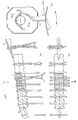
- the device for separating consists essentially of hollow spindle 1 and arranged therein a pin 4, 4 '; 5.5 'shafts 2a, 2b; 3a, 3b.
- a pin 4, 4 ' In the spindle 1 are tangential oblique oblong holes 7,7 '; 8,8' arranged, wherein the course of the two on the drawing ( Figure 2) arranged on the left Elongated holes 7,7 'opposite to that of the two on the right arranged elongated holes 8,8 '.
- the pins 4,4 ', 5,5' protrude radially from the inside of the spindle 1 outward.
- the shafts 2a, 2b, in which the pins 4, 5 are fastened via screws 11, are designed as hollow shafts and accommodate the shafts 3a, 3b designed as solid shafts, in which the pins 4 ', 5' are also fastened via screws 11 .
- the shafts 2a, 3a are arranged in mirror image with respect to the shafts 2b, 3b.
- the shafts 2a, 2b, 3a, 3b are axially displaceable and are supported against pressure springs 9a, 9b and 10a, 10b.
- the springs 9a, 9b; 10a, 10b are pretensioned via pressure screws 6a, 6b, which can be screwed into the spindle 1, and the necessary force, which leads to a deflection movement of the pins 4, 4 ', 5, 5', is thereby determined. Due to the mirror-image arrangement of the shafts 2a, 3a; 2b, 3b, the pins 4,4 ';5,5' in the elongated holes 7,7 ';8,8' lead an opposite movement analogous to the arrows P 1 , P 2 (FIG 12) off.
- the clothes hanger hooks reach the spindle 1 via the slide 24 arranged at a slope.
- individual hangers are crossed with one another.
- the spindle 1 rotates about its central axis according to the arrows E.
- the stirrup hooks - two of which are designated 20.21 by way of example - are transported in the conveying direction F.
- You get into the threads 1 'of the spindle 1 individual stirrups are transported unhindered past the pins 4,4', 5,5 '.
- Cross-shaped hangers are gripped by the first pin 5 in that it is inserted with the bent tip 12 between the two hooks 20, 21 and lifts the upper hook and exposes it.
- the hanger hooks 20, 21 are isolated, they pass the subsequent pins 5 ', 4', 4 unhindered. If there are more than two bow hooks one above the other, the bow hook in relation to the transport direction F is first gripped by the first pin 5 and lifted out. The next pin 5 'then detects the hanger hook behind it, etc. If the hanger hooks 20, 21 are too tightly clamped to one another, the pins 4, 4', 5, 5 'can dodge according to the arrows P 1 , P 2 (FIG. 12).
- Figure 7 shows how the pin 5 in the direction of the superimposed Bow hook 20, 21 rotated
- Figure 8 can be removed, as he between the necks of the hooks 20,21 with the tip 12th dips and presses apart according to Figure 4 and the hanger hook 20 lifts over the hook 21, so that this as in Figure 10 shown in two successive threads 1 ' the spindle 1 come to rest. Hitting a hook directly on one Tip 12 of a pin 4,4 ', 5,5' and threatens to tilt, so there the pin 4,4 ', 5,5' through the resilient mounting of its shaft 2a, 2b, 3a, 3b after the pressure and the hook slips on the tip past.
- FIG. 13 The design of the housing 25 and the gap 26 is shown in FIG. 13 removable, the otherwise another embodiment of the Invention shows.
- a spindle is a hollow body Tube 27 has been selected in the same way as the previous description five pins are stored next to each other in parallel.
- the tube 27 preferably with a slight slope arranged in the conveying direction F to ensure safe transport to ensure.
- a delivery rod 23 can be provided, along which the bracket or Bow hooks can slip to their further destination.
- FIGS. 14 and 15 show a further exemplary embodiment of a Separating device.
- the pins 32, 32a, 33, 33a and 34, 34a combined in pairs and in pairs by 90 ° staggered.
- the pins 32, 32a, 33, 33a, 34, 34a are screwed into bolts 31, 31a.
- the bolts 31, 31a, of which each carries only one pin, is supported by compression springs 36 in from a bore in the shaft 30.
- the shaft 30 is not a pure hollow body, but it is with the bolts 31, 31a provided adapted holes. Via the clamping screws 37 the pins 32, 32a are clamped in the bolts 31, 31a.
- the pins 32, 32a, 33, 33a, 34, 34a can be bent or straight be.
- the pins are radially offset so that their Longitudinal axis not aligned with a radial beam, but in one parallel distance b runs to this.
Landscapes
- Engineering & Computer Science (AREA)
- Mechanical Engineering (AREA)
- Chain Conveyers (AREA)
- Load-Engaging Elements For Cranes (AREA)
- Feeding Of Articles To Conveyors (AREA)
Description
- Figur 1 -
- den Axialschnitt durch die erfindungsgemäße Vorrichtung,
- Figur 2 -
- den Schnitt entlang der Linie II-II nach Figur 1,
- Figur 3 -
- die Seitenansicht nach Figur 1,
- Figur 4 -
- die Seitenansicht der erfindungsgemäßen Vorrichtung mit darauf transportierten Bügelhaken,
- Figur 5 -
- die Draufsicht gemäß Sichtpfeil V nach Figur 4,
- Figur 6 -
- die Seitenansicht der erfindungsgemäßen Vorrichtung,
- Figuren 7-10 -
- den Vereinzelungsvorgang in chronologischer Reihenfolge,
- Figur 11 -
- die schematische Darstellung der Stellung der Stifte jeweils entsprechend einem Zeitpunkt nach Figuren 7 bis 10 gemäß Sichtpfeil X,
- Figur 12 -
- die Ansicht gemäß Sichtpfeil IX nach Figur 5,
- Figur 13 -
- ein weiteres Ausführungsbeispiel der Erfindung,
- Figur 14 -
- ein weiteres Ausführungsbeispiel der Erfindung,
- Figur 15 -
- die Ansicht gemäß Sichtpfeil XV nach Figur 14.
Claims (16)
- Vorrichtung zum Vereinzeln von übereinander verkreuzten Haken (20,21) eines auf Bügeln (22) oder dergleichen hängend transportierten Fördergutes, mit einem sich drehenden, im wesentlichen zylinderförmigen zumindest teilweise hohlen Körper (1), den die Haken (20, 21) umgreifen und von dem sie transportiert werden, wobei der Körper (1) eine radial nach außen weisende, zwischen zwei Haken (20,21) greifende Vereinzelungeinrichtung aufweist, dadurch gekennzeichnet, daß die Vereinzelungseinrichtung eine Mehrzahl parallel angeordneter Stifte (4,4',5,5') aufweist, die im Inneren des Körpers (1) federnd gelagert sind und über Langlöcher (7,7',8,8') aus dem Körper (1) herausragen.
- Vorrichtung nach Anspruch 1, dadurch gekennzeichnet, daß die Stifte (4,4',5,5') an einer axial verschiebbar gelagerten, drehbaren Welle (2a,2b,3a,3b) befestigt sind.
- Vorrichtung nach Anspruch 2, dadurch gekennzeichnet, daß jeder Stift (4,4',5,5') an einer separaten Welle (2b,3b,2a,3a) befestigt ist.
- Vorrichtung nach Anspruch 3, dadurch gekennzeichnet, daß die Wellen (2a,3a,2b,3b) ineinandergesteckt und in symmetrischer Anordnung gegenüber einer radialen Linie (A) spiegelbildlich im Körper (1) angeordnet sind.
- Vorrichtung nach Anspruch 4, dadurch gekennzeichnet, daß vier Stifte (4,4',5,5') vorgesehen sind und davon zwei auf Hohlwellen (2a,2b) und zwei auf Vollwellen (3a,3b) angeordnet sind und je eine Vollwelle (3a,3b) in einer Hohlwelle (2a,2b) verläuft.
- Vorrichtung nach Anspruch 4, dadurch gekennzeichnet, daß die Langlöcher (7,7',8,8') tangential schräg verlaufen.
- Vorrichtung nach Anspruch 2, dadurch gekennzeichnet, daß die Stifte (4,4',5,5') mittels Schrauben (11) in der Welle (2a,2b,3a,3b) befestigt sind.
- Vorrichtung nach Anspruch 1, dadurch gekennzeichnet, daß die Stifte (4,4',5,5') eine abgekröpfte Spitze (12) aufweisen.
- Vorrichtung nach Anspruch 1, dadurch gekennzeichnet, daß der Körper (1) eine Spindel ist.
- Vorrichtung nach Anspruch 9, dadurch gekennzeichnet, daß die Spindel (1) beidseitig mit einer Welle verbunden ist.
- Vorrichtung nach Anspruch 1, dadurch gekennzeichnet, daß die Stifte (32,32a,33,33a,34,34a,35,35a) axial und radial versetzt angeordnet sind.
- Vorrichtung nach Anspruch 1, dadurch gekennzeichnet, daß für jeden Stift (4,4',5,5',32,32a,33,33a,34,34a,35,35a) eine kombinierte axiale und radiale Bewegung ausführbar ist.
- Vorrichtung nach Anspruch 1, dadurch gekennzeichnet, daß die Stifte (32,32a,33,33a,34,34a,35,35a) jeweils in einem axial gefederten Bolzen (31,31a) gelagert sind, und mindestens acht Bolzen (31a) im Inneren des Körpers (1) vorgesehen sind.
- Vorrichtung nach Anspruch 1, dadurch gekennzeichnet, daß die Stifte (4,4',5,5',32,32a,33,33a,34,34a,35,35a) in einer elastischen Masse, wie Gummi oder dergleichen vergossen sind.
- Vorrichtung nach Anspruch 11, dadurch gekennzeichnet, daß die Stifte (32,32a,33,33a,34,34a,35,35a) jeweils paarweise radial um 90° versetzt angeordnet sind.
- Vorrichtung nach einem oder mehreren der vorstehenden Ansprüche, dadurch gekennzeichnet, daß die Stifte (32,32a,33,33a,34,34a,35,35a) jeweils so angeordnet sind, daß ihre zentrale Achse einen parallelen Abstand (b) zu einem radialen Strahl einnimmt.
Applications Claiming Priority (2)
| Application Number | Priority Date | Filing Date | Title |
|---|---|---|---|
| DE19514604A DE19514604C2 (de) | 1995-04-20 | 1995-04-20 | Vorrichtung zum Vereinzeln von übereinander verkreuzten Bügelhaken |
| DE19514604 | 1995-04-20 |
Publications (2)
| Publication Number | Publication Date |
|---|---|
| EP0738672A1 EP0738672A1 (de) | 1996-10-23 |
| EP0738672B1 true EP0738672B1 (de) | 1999-05-06 |
Family
ID=7759999
Family Applications (1)
| Application Number | Title | Priority Date | Filing Date |
|---|---|---|---|
| EP96100825A Expired - Lifetime EP0738672B1 (de) | 1995-04-20 | 1996-01-20 | Vorrichtung zum Vereinzeln von übereinander verkreuzten Bügelhaken |
Country Status (4)
| Country | Link |
|---|---|
| US (1) | US5788054A (de) |
| EP (1) | EP0738672B1 (de) |
| JP (1) | JPH08290817A (de) |
| DE (2) | DE19514604C2 (de) |
Families Citing this family (9)
| Publication number | Priority date | Publication date | Assignee | Title |
|---|---|---|---|---|
| AU2005200211B2 (en) * | 2001-08-06 | 2005-02-24 | Memjet Technology Limited | Printing device with printing control based on integrated circuit device of printing cartridge |
| DE10152926A1 (de) * | 2001-10-26 | 2003-05-08 | Wf Logistik Gmbh | Schneckenförderer zum Transport von an Hängeträgern hängendem Fördergut |
| DE10163427A1 (de) * | 2001-12-21 | 2003-07-03 | Wf Logistik Gmbh | Schneckenförderer zum Transport von an Hängeträgern hängendem Fördergut |
| DE502004000627D1 (de) * | 2004-03-17 | 2006-06-29 | Tfs Global Hanger Man Gmbh | Verfahren und Vorrichtung zur Arretierung von Kleiderbügelhaken |
| CH712560A1 (de) | 2016-05-31 | 2017-12-15 | Ferag Ag | Laufwagen für ein schienengeführtes Fördersystem sowie Fördersystem mit einem solchen Laufwagen. |
| EP3315433B1 (de) * | 2016-11-01 | 2020-07-15 | Ferag AG | Übergabevorrichtung für produkteträger mit haltemitteln |
| ES2712176B2 (es) * | 2017-11-07 | 2019-12-05 | Tecnimusa S L | Sistema separador de perchas |
| CH714647A1 (de) * | 2018-02-15 | 2019-08-15 | Ferag Ag | Trennvorrichtung zum Trennen von überkreuzten Haken. |
| US12441554B2 (en) * | 2022-05-16 | 2025-10-14 | Walmart Apollo, Llc | Hangar guide |
Family Cites Families (7)
| Publication number | Priority date | Publication date | Assignee | Title |
|---|---|---|---|---|
| US2947407A (en) * | 1957-05-15 | 1960-08-02 | Byron A Wood | Conveyor mechanism for garments on hangers |
| US3207262A (en) * | 1960-03-21 | 1965-09-21 | Vic Mfg Company | Article storing and delivering conveyor |
| JPS62235120A (ja) * | 1986-04-07 | 1987-10-15 | Hitachi Ltd | ベルト分離供給装置 |
| NL8801552A (nl) * | 1988-06-17 | 1990-01-16 | Johannes Gerhardus Christianus | Inrichting voor het van elkaar scheiden en stuksgewijs doorvoeren van op een stang aangevoerde platte voorwerpen. |
| DE8905995U1 (de) * | 1989-05-13 | 1989-07-13 | Pavel, Wilfried, 4802 Halle | Förderschnecke für auf Kleiderbügel hängende Bekleidungsstücke |
| US5305896A (en) * | 1992-09-11 | 1994-04-26 | Branch Thomas R | Apparatus for separating crossed garment hangers |
| DE4126615C2 (de) * | 1991-08-12 | 1994-08-18 | Gaertner Franz | Verfahren zum sortierenden Transportieren von Gegenständen und Zwischenhaken zu seiner Durchführung |
-
1995
- 1995-04-20 DE DE19514604A patent/DE19514604C2/de not_active Expired - Fee Related
-
1996
- 1996-01-20 DE DE59601805T patent/DE59601805D1/de not_active Expired - Fee Related
- 1996-01-20 EP EP96100825A patent/EP0738672B1/de not_active Expired - Lifetime
- 1996-02-08 JP JP8022685A patent/JPH08290817A/ja not_active Withdrawn
- 1996-04-08 US US08/629,234 patent/US5788054A/en not_active Expired - Fee Related
Also Published As
| Publication number | Publication date |
|---|---|
| US5788054A (en) | 1998-08-04 |
| DE59601805D1 (de) | 1999-06-10 |
| JPH08290817A (ja) | 1996-11-05 |
| DE19514604A1 (de) | 1996-10-24 |
| EP0738672A1 (de) | 1996-10-23 |
| DE19514604C2 (de) | 1997-09-04 |
Similar Documents
| Publication | Publication Date | Title |
|---|---|---|
| DE69405650T2 (de) | Sternrad mit Justiervorrichtung für unterschiedlich geformte Behälter | |
| DE19816239A1 (de) | Vorrichtung zum Einbringen und/oder Ausbringen von Behältern in bzw. aus einem Behandlungsraum | |
| EP1256637B1 (de) | Werkstückträger | |
| DD300820A5 (de) | Vorrichtung zum Ausrichten von Gegenständen, insbes. zur Beschickung vonEinwickelmaschinen | |
| DE60108546T2 (de) | Vorrichtung für Maschinen zum Umordnen von Behältern, mit automatischen Mitteln zum Ausrichten und Abwerfen eines empfangenen Behälters | |
| DE4340101A1 (de) | Vorrichtung zum Trennen von Kartoffeln von Beimengungen | |
| DE19514604C2 (de) | Vorrichtung zum Vereinzeln von übereinander verkreuzten Bügelhaken | |
| EP0566531B1 (de) | Einrichtung zum Sammeln und anschliessenden Heften gefalteter, bogenförmiger Druckprodukte | |
| EP0312755B1 (de) | Transporteur für kontinuierlich anfallende Flächengebilde, insbesondere Druckereiprodukte | |
| DE4442586B4 (de) | Vorrichtung zum Verteilen von Gefäßen | |
| DE60219978T2 (de) | Vorrichtung zum Anordnen von Behältern, insbesondere von Flaschen, in gleichen Abständen | |
| EP0799580A2 (de) | Schälmaschine | |
| DE29514099U1 (de) | Transportstern für Gefäße | |
| EP3527510A1 (de) | Trennvorrichtung zum trennen von überkreuzten haken | |
| EP0565932A1 (de) | Warenabzugsvorrichtung für Flachstrickmaschinen | |
| AT407210B (de) | Lade- und fördervorrichtung für landwirtschaftliche erntemaschinen, insbesondere selbstladewagen | |
| DE3823488A1 (de) | Huelsenzubringevorrichtung fuer textilmaschinen | |
| DE29519284U1 (de) | Fördereinrichtung | |
| WO1996037445A1 (de) | Rinneneinrichtung für eine i.s.-glasformmaschine | |
| DE102015114567B4 (de) | Einsetzbare Ansteuerungsvorrichtung und Transportvorrichtung für Behälter, sowie schwebend positionierte Ansteuerungsvorrichtung | |
| DE2644500C3 (de) | Vorrichtung zum Zuführen von Kartuschhülsen o.a. einendig geschlossenen, hohlen Werkstücken, in einer bestimmten Ausrichtung | |
| DE10247362A1 (de) | Neck-Handling-Transportstern für den Transport von Behältern | |
| DE2820315B2 (de) | Sortierstern für Flaschen o.dgl | |
| DE60224134T2 (de) | Vorrichtung zur Dekoration von keramischen Gegenständen | |
| CH690576A5 (de) | Vorrichtung zum Verarbeiten von Druckereiprodukten. |
Legal Events
| Date | Code | Title | Description |
|---|---|---|---|
| PUAI | Public reference made under article 153(3) epc to a published international application that has entered the european phase |
Free format text: ORIGINAL CODE: 0009012 |
|
| 17P | Request for examination filed |
Effective date: 19960816 |
|
| AK | Designated contracting states |
Kind code of ref document: A1 Designated state(s): DE FR GB IT |
|
| 17Q | First examination report despatched |
Effective date: 19970530 |
|
| GRAG | Despatch of communication of intention to grant |
Free format text: ORIGINAL CODE: EPIDOS AGRA |
|
| GRAG | Despatch of communication of intention to grant |
Free format text: ORIGINAL CODE: EPIDOS AGRA |
|
| GRAH | Despatch of communication of intention to grant a patent |
Free format text: ORIGINAL CODE: EPIDOS IGRA |
|
| GRAH | Despatch of communication of intention to grant a patent |
Free format text: ORIGINAL CODE: EPIDOS IGRA |
|
| GRAA | (expected) grant |
Free format text: ORIGINAL CODE: 0009210 |
|
| AK | Designated contracting states |
Kind code of ref document: B1 Designated state(s): DE FR GB IT |
|
| GBT | Gb: translation of ep patent filed (gb section 77(6)(a)/1977) |
Effective date: 19990507 |
|
| REF | Corresponds to: |
Ref document number: 59601805 Country of ref document: DE Date of ref document: 19990610 |
|
| ET | Fr: translation filed | ||
| ITF | It: translation for a ep patent filed | ||
| PLBE | No opposition filed within time limit |
Free format text: ORIGINAL CODE: 0009261 |
|
| STAA | Information on the status of an ep patent application or granted ep patent |
Free format text: STATUS: NO OPPOSITION FILED WITHIN TIME LIMIT |
|
| 26N | No opposition filed | ||
| REG | Reference to a national code |
Ref country code: GB Ref legal event code: IF02 |
|
| PGFP | Annual fee paid to national office [announced via postgrant information from national office to epo] |
Ref country code: GB Payment date: 20050112 Year of fee payment: 10 |
|
| PGFP | Annual fee paid to national office [announced via postgrant information from national office to epo] |
Ref country code: FR Payment date: 20050119 Year of fee payment: 10 |
|
| PG25 | Lapsed in a contracting state [announced via postgrant information from national office to epo] |
Ref country code: GB Free format text: LAPSE BECAUSE OF NON-PAYMENT OF DUE FEES Effective date: 20060120 |
|
| PG25 | Lapsed in a contracting state [announced via postgrant information from national office to epo] |
Ref country code: FR Free format text: LAPSE BECAUSE OF NON-PAYMENT OF DUE FEES Effective date: 20060131 |
|
| PGFP | Annual fee paid to national office [announced via postgrant information from national office to epo] |
Ref country code: IT Payment date: 20060131 Year of fee payment: 11 |
|
| PGFP | Annual fee paid to national office [announced via postgrant information from national office to epo] |
Ref country code: DE Payment date: 20060322 Year of fee payment: 11 |
|
| GBPC | Gb: european patent ceased through non-payment of renewal fee |
Effective date: 20060120 |
|
| REG | Reference to a national code |
Ref country code: FR Ref legal event code: ST Effective date: 20060929 |
|
| PG25 | Lapsed in a contracting state [announced via postgrant information from national office to epo] |
Ref country code: DE Free format text: LAPSE BECAUSE OF NON-PAYMENT OF DUE FEES Effective date: 20070801 |
|
| PG25 | Lapsed in a contracting state [announced via postgrant information from national office to epo] |
Ref country code: IT Free format text: LAPSE BECAUSE OF NON-PAYMENT OF DUE FEES Effective date: 20070120 |