EP0738470B1 - Dispositif pour former en série des objets plats de formé et d'épaisseur réglables, par dépôt sur un support d'une substance relativement fluide - Google Patents
Dispositif pour former en série des objets plats de formé et d'épaisseur réglables, par dépôt sur un support d'une substance relativement fluide Download PDFInfo
- Publication number
- EP0738470B1 EP0738470B1 EP96400775A EP96400775A EP0738470B1 EP 0738470 B1 EP0738470 B1 EP 0738470B1 EP 96400775 A EP96400775 A EP 96400775A EP 96400775 A EP96400775 A EP 96400775A EP 0738470 B1 EP0738470 B1 EP 0738470B1
- Authority
- EP
- European Patent Office
- Prior art keywords
- drum
- substance
- shaft
- wall
- distributing
- Prior art date
- Legal status (The legal status is an assumption and is not a legal conclusion. Google has not performed a legal analysis and makes no representation as to the accuracy of the status listed.)
- Expired - Lifetime
Links
Images


Classifications
-
- A—HUMAN NECESSITIES
- A21—BAKING; EDIBLE DOUGHS
- A21B—BAKERS' OVENS; MACHINES OR EQUIPMENT FOR BAKING
- A21B5/00—Baking apparatus for special goods; Other baking apparatus
- A21B5/02—Apparatus for baking hollow articles, waffles, pastry, biscuits, or the like
- A21B5/03—Apparatus for baking hollow articles, waffles, pastry, biscuits, or the like for baking pancakes
Definitions
- the present invention relates to a device for performing in series on a any support for adjustable thickness discs formed from various substances of relatively fluid consistency: creamy, pasty, powdery, etc.
- the device can find applications in many fields, especially in manufacturing cycles of filtration discs or discs in refractory materials such as ceramics, or in industries electronic to spread on circuits, photo-sensitive varnishes or soldering cream prior to welding operations.
- the device according to the invention finds interesting applications in the agro-food industries especially for the automated manufacture of pancakes or patties etc.
- various examples of implementation of devices for making pancakes or pancakes are described in particular in FR patents 2,590,388 or US patents 4,583,451, 4,733,608 or 5,077,072.
- the device according to the invention makes it possible to form flat objects in series and in particular thin pancakes of a particular shape, on an application wall any, from a substance of sufficiently fluid consistency, comprising a distribution drum rotatably mounted on a hollow shaft, suitable for be placed in contact with the application wall, the wall of this dispensing drum comprising at least one opening, the shape of which is chosen in relation to the form to give to each flat object, means connected to the tree to introduce this stuff inside the drum.
- This type of device is known from document FR-A-1578102.
- the device includes a planar distribution element for channeling and spread the substance on the application surface through said opening, this distribution element which communicates with the interior of the tree, being arranged radially between the shaft and the inner face of the drum and guide means to keep the distribution element in contact with it.
- the means for introducing the substance include a container containing the substance, which is connected to the inside of the tree which has at least one radial opening communicating the interior of the shaft with the inside of the timing drum.
- the device advantageously includes a pumping circuit including said container, adapted to circulate the substance continuously along the element of division.
- the distribution element is for example associated with the tree and comprises by example two plates arranged on either side of said opening, delimiting between them, in the vicinity in their zone of contact with the inner wall of the drum, a relatively narrow groove, and it is guided by guide means associated with the shaft which are adapted to press the groove against the inner wall of the drum.
- These guide means comprise for example one or more sockets of section adapted to that of the axial opening in the shaft.
- the distribution element preferably comprises housings for the guide means making it possible to decouple them from the shaft.
- the device comprises for example two arms support fixed to a pivot axis, allowing the drum to tilt between a working position in contact with the application wall and a release and motor means for moving the drum without sliding distribution relative to the application wall.
- the application wall is the surface of an elongated table
- the pivot axis of the two support arms is secured to a carriage movable relative to the table
- the driving means include a gearmotor cooperating with drive elements synchronized drum in rotation and carriage in translation, such as for example a drum drive belt and a rack to translate the trolley in relation to the table.
- the application wall is the surface of a cylinder on which the dispensing drum rests in the position of work
- the driving means comprise for example and elements for setting in synchronized rotation in opposite direction to each other of the cylinder and the drum comprising for example a gear motor cooperating with a belt drum drive.
- the application wall is the surface of an endless conveyor belt on which the dispensing drum rests in the working position, the drive means comprising drive elements synchronized drum in rotation and conveyor belt in translation.
- the device may also include means for cooking flat objects after they have been deposited on the application wall: cooking plates positioned in depending on the distribution of the deposits of substance by the distribution drum, or infrared radiation cooking tunnel, associated with the conveyor belt, which is preferably adapted to be crossed by infrared rays.
- the device may also advantageously further include means for washing and means for moving the dispensing drum between a position in contact with the application wall and a rest position in the vicinity washing means.
- the means for introducing substance inside the dispensing drum have thermoregulation means which can be combined with the substance container to cool it, refrigerate or preheat as appropriate, and / or still installed on a closed circuit between the container and the dispensing drum for example to impose a conservation temperature.
- the device may include means to angularly move the ramp relative to the application wall.
- the device has many advantages. Its simplicity of design is combines great ease of use and maintenance, and is relatively low expensive; the shape and thickness of flat objects: discs, pancakes, etc., products are very regular. According to the modes of implementation of the distribution drum, can vary in significant proportions the amount of flat objects it is possible to manufacture, so the device can be suitable for both both artisanal and industrial applications.
- the discs or pancakes mentioned in the following description are nonlimiting examples of flat objects which it is possible to manufacture with the device according to the invention.
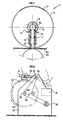
- the distributor shown in FIG. 1 suitable for the manufacture of any object flat comprises first of all an external drum or rotor 1 comprising a tube 2 terminated at its two opposite ends by two flanges 3.
- the thickness of the wall outside of tube 2 is chosen according to the thickness of the discs or pancakes deposit.
- an opening 4 is formed, the shape of which is adapted to that of the discs or wafers to be deposited, for example an opening circular.
- the drum 1 is rotatably mounted by means of two ball bearings 7, on a fixed hollow shaft 8 carried by two arms 9.
- the outer cages of these two ball bearings 7 are secured to the flanges 3 by covers 10 fixed by screw action 11, with lip seals 12 for sealing.
- the cages interior of these same ball bearings 7 are made integral with the shaft 8 by the action of nuts 13 acting axially through the support arms 9, on spacers 14.
- Two tubular guides 15 provided externally with seals 16, are arranged in openings made radially in the shaft 8.
- a distribution ramp 17 made up (Fig. 2) of two parallel plates integral with one another advantageously produced in a temperature resistant antifriction plastic.
- the two plates of the ramp 17 define a groove 18 which is pressed against the inner face of the drum 1 by the action of springs 19 bearing against an end face of the two guides 15.
- the tubular guides 15 make the interior of the shaft 8 communicate with the face inside of the drum 1 between the two plates of the ramp 17.
- the drum 1 is rotated by means of a belt notched drive 20 passing around the cover 10.
- the support arms 9 can pivot around an axis 21 integral with a rigid frame 22 (Fig. 3-5) between a working position W where the drum 1 is supported on a wall 23 to deposit there discs or pancakes, and a rest position R, this wall, according to the modes of realization and / or applications, which can be flat (Fig. 2, 3) or even cylindrical (Fig. 5).
- the substance to be deposited is introduced through the interior of the tree 8. It flows through the tubular guides 15 and the groove 18 in the distribution ramp 17 and spreads on the application wall 23 through the opening 4 in the drum 1.
- the circulation of the substance can be effected by simple gravity or by means of example of a pump (not shown).
- the injection rate of the substance is regular to avoid any stagnation.
- each guide has a profiled collar 24 (Fig. 2) which is normally pressed against the shaft 8 by the springs 19.
- the distribution ramp is provided with housings 25 for each of the flanges 24, sufficiently deep to allow complete release of the guides 15 outside the shaft 8. Lugs 26 are fixed to the ramp 8 under which each of the profiled flanges 24 can be locked by rotation of the guides 15 around their axis.
- the frame 22 includes a table elongated 27 whose surface constitutes the application wall 23.
- the arms 9 associated with the drum 1 are fixed to a carriage 28 which can slide along the table along cylindrical rails 29.
- a gear motor 30 (Fig.4) drives a toothed wheel associated with the carriage 28 which meshes with a rack 31a fixed to the table 27 parallel to its longitudinal axis.
- the same geared motor 30 drives the drum distribution 1 via the toothed belt 20.
- a washing tank 31 is preferably installed at one end of the table 27, above which the drum dispenser in rest position R can be brought.
- the drum being tilted in the working position W at one end of the table 27, we actuates the gear motor 30 so as to obtain a translation of the carriage 28 combined with a rotation of the dispensing drum 1.
- the substance injected into the same time by the shaft 8 (Fig.1), is placed on the table 27 with a distribution which depends on the shape of the opening 4 if it is unique or on the distribution of openings if there are several. Then, the carriage 28 is returned to its initial position for a new cycle.
- the formation of discs or pancakes is made continuous using a cylindrical deposit wall.
- the drum distribution 1 in working position W rolls on a cylinder 33 arranged horizontally, the axis 34 of which is supported by the frame 22.
- the support arms are connected to the axis 21 which can pivot relative to the frame 22 between its working position W and a rest position R where the dispensing drum 1 is found above the cleaning tank 31 also.
- the gear motor 30 rotates in the opposite direction one on the other the cylinder 33 and the distribution drum 1.
- the drive is performed at by means of a belt 35 which drives a pulley 36 integral with the axis 34 of the cylinder 33 by means of a return pulley 37 and a pulley 38 secured to the axis 21 pivoting of the arms, and the toothed belt 20 which drives the drum 1.
- hotplates 32 on the circumference of cylinder 33 with spacings chosen according to the diameter of the drum and its opening (s) 4, so that the deposits of substance are do at their locations.
- Known means such as electric brush collector, allows transmission to the cooking plates of electrical energy. This embodiment is suitable for a process of continuous manufacturing.
- One or more cooking means with infrared rays can also be arranged above the table 27 or around the cylinder 33 of the device according to the embodiments of Figs. 3-5, so as to cook the discs deposited on both sides, if required by the application.
- the production of discs or pancakes on a larger scale can be obtained by implementing the embodiment of FIG. 6
- Belt tension can be adjusted by a spring tension element 42.
- the belt passes between the drum 1 and an idler roller 43 supported by the frame 22.
- the geared motor 30 drives rotation of one of the rollers 40 by a belt 44, and this communicates its movement to the drum 1 by the toothed belt 20.
- a removal device (not shown) can be placed at the end of the mat, on the side of the roller 41 to take off and remove the discs or pancakes as well trained.
- the conveyor belt 40 is passed through a tunnel cooking 45 fitted with infrared cooking rails 46.
- the mat is in this case preferably made of a material transparent to infrared waves such as glass fabric coated with fluorinated plastic.
- the forward speed of the conveyor belt 40 and the heating power are adjusted so that the discs or pancakes reach a cooking point sufficient at the end of the tunnel.
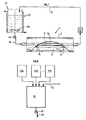
- the device includes a distribution system shown schematically in Fig. 7, which is adapted to establish a continuous circulation of the dough at level of the contact zone between the distribution ramp 17 and the inner face of the drum 1. It comprises a reservoir 47 for the paste or substance, means 48 for mixing of the substance inside the reservoir 47 and a closed pumping circuit connected to the distribution drum 1.
- This circuit includes a pump 49, of the type peristaltic for example, inserted on a tube 50 connecting the pump to a first end of the axial duct 8a.
- the introduced substance is deflected by a first of the two tubular guides 15 towards the distribution ramp 17. It flows along the contact zone between the base of the ramp 17 and either the deposit plate accessible through the opening 4 of the tube 2 at the locations provided for depositing and cooking) or the inner wall of the tube 2 between the locations provided. Unregistered substance including that is in excess at the planned storage locations, is taken up at the second level tubular guide 15 and returns to the axial channel 8a of the shaft, to which a second tube 51 which brings it back to the reservoir 47.
- This diversion of the circulation of the substance towards the deposit zone can be obtained by partitioning the hollow shaft 8 at the locations of branches to the tubular guides 15, either by using a solid shaft in the axis of which are pierced portions of channels of sufficient length to establish the communication with guides 15.
- the device may include a means 52 for thermoregulating the reservoir 47, adapted to the application. It can be a cooling element or refrigeration when it is useful for the good conservation of the substance in particular in the food sector. either to cool it down before recycling it during operation, i.e. between two periods of use of the device to avoid any transfer operation.
- It can also be a device for preheating the substance to bring it to a certain temperature, necessary to bring it to a certain degree fluidity or consistency.
- the device can also include a heat exchanger 53 installed on the circuit at tube 51 for example, to bring or carry the substance crisp at a set temperature.
- Embodiments have been described where the dispensing drum has a single opening 4 and two hollow guides 15 for injecting the substance to be spread. It would not, however, depart from the scope of the present invention to spare several openings with peripheral and lateral spacing suitable for other application, nor by changing the number and the shape of the openings which make communicate the channel inside the shaft 8 with the inside of the drum distribution.
Landscapes
- Life Sciences & Earth Sciences (AREA)
- Engineering & Computer Science (AREA)
- Food Science & Technology (AREA)
- Manufacturing And Processing Devices For Dough (AREA)
- Confectionery (AREA)
- Baking, Grill, Roasting (AREA)
- Detergent Compositions (AREA)
- Materials For Photolithography (AREA)
Description
- la Fig. 1 montre le distributeur de matière vu de face, en coupe longitudinale;
- la Fig.2 montre le distributeur de matière en coupe transversale;
- les Fig.3 et 4 montrent un premier mode de réalisation du dispositif avec un distributeur de matière adapté à déposer des objets plats tels que des galettes, à intervalles réguliers sur un support plat sur lequel il roule;
- la Fig. 5 montre un deuxième mode de réalisation du dispositif avec un distributeur de matière adapté à déposer des objets plats sur un support cylindrique sur lequel il roule;
- la Fig.6 montre un troisième mode de réalisation du dispositif avec un distributeur de matière adapté à déposer des objets plats à intervalles réguliers sur un tapis transporteur passant dans un tunnel de cuisson; et
- la Fig.7 montre un mode de réalisation d'un système d'alimentation continu du distributeur en substance à déposer.
Claims (24)
- Dispositif pour former en série des objets plats et notamment des galettes minces de forme particulière, sur une paroi d'application (23) quelconque, à partir d'une substance de consistance suffisamment fluide, comportant un tambour de distribution (1) monté rotatif sur un arbre creux (8), adapté à être placé au contact de la paroi d'application (23), la paroi de ce tambour de distribution (1) comportant au moins une ouverture (4) dont la forme est choisie en rapport avec la forme à donner à chaque objet plat, des moyens reliés à l'arbre pour introduire de cette substance à l'intérieur du tambour, caractérisé en ce qu'il comporte un élément de répartition plan (17) pour canaliser et étaler de la substance sur la surface d'application au travers de ladite ouverture, cet élément de répartition qui communique avec l'intérieur de l'arbre (8), étant disposé radialement entre l'arbre (8) et la face intérieure du tambour et des moyens de guidage (15,19) pour maintenir au contact de celle-ci l'élément de répartition (17).
- Dispositif selon la revendication 1, caractérisé en ce que les moyens pour introduire la substance comprend un récipient (47) contenant la substance, qui est relié à l'intérieur de l'arbre (8) lequel comporte au moins un orifice radial faisant communiquer l'intérieur de l'arbre avec l'intérieur du tambour de distribution (1).
- Dispositif selon la revendication précédente, caractérisé en ce qu'il comporte un circuit de pompage (47-52) incluant ledit récipient (47), adapté à faire circuler la substance en continu le long de l'élément de répartition (17).
- Dispositif selon l'une des revendications précédentes, caractérisé en ce que l'élément de répartition (17) est associé à l'arbre (8) et comporte deux plaques disposées de part et d'autre de ladite ouverture, délimitant entre elles, au voisinage dans leur zone de contact avec la paroi intérieure du tambour, une rainure (18) relativement étroite.
- Dispositif selon la revendication précédente, caractérisé en ce qu'il comporte des moyens (15, 19) de guidage de l'élément de répartition (17) associés à l'arbre (8) adaptés à plaquer la rainure (18) contre la paroi intérieure du tambour.
- Dispositif selon la revendication précédente, caractérisé en ce que les moyens de guidage (15, 19) de l'élément de répartition (17) comportent au moins une douille de section adaptée à celle de ladite ouverture axiale.
- Dispositif selon l'une des revendications précédentes, caractérisé en ce que l'élément de répartition (17) comporte des logements (24-26) pour les éléments de guidage (15) permettant de les découpler de l'arbre (8).
- Dispositif selon l'une des revendications précédentes, caractérisé en ce qu'il comporte deux bras de support (9) solidaires d'un axe de pivotement (21), permettant de faire basculer le tambour de distribution (t1) entre une position de travail (W) au contact de la paroi d'application et une position de dégagement (R).
- Dispositif selon l'une des revendications précédentes, caractérisé en ce qu'il comporte des moyens moteurs pour déplacer sans glissement le tambour de distribution (1) relativement à ladite paroi d'application (23).
- Dispositif selon la revendication précédente, caractérisé en ce que la paroi d'application est la surface d'une table allongée (27), l'axe (21) de pivotement des deux bras de support (9) étant solidaire d'un chariot (28) déplaçable relativement à la table et les moyens moteurs comportant des éléments (20, 31, 32) d'entraínement synchronisés du tambour en rotation et du chariot en translation.
- Dispositif selon la revendication 9, caractérisé en ce que la paroi d'application est la surface d'un cylindre (33) sur lequel repose le tambour de distribution (1) en position de travail (W), et les moyens moteurs comportent des éléments (35-38) pour la mise en rotation synchronisée en sens inverse l'un de l'autre du cylindre et du tambour.
- Dispositif selon la revendication 9,caractérisé en ce que la paroi d'application est la surface d'un tapis transporteur sans fin (39) sur lequel repose le tambour de distribution (1) en position de travail (W), les moyens moteurs comportant des éléments (30, 44, 20) d'entraínement synchronisé du tambour de distribution (1) en rotation et du tapis transporteur (39) en translation.
- Dispositif selon la revendications 11, caractérisé en ce que les moyens moteurs comportent un motoréducteur (30) coopérant avec une courroie (20) d'entraínement du tambour, et avec une crémaillère (31A) pour translater le chariot (28) par rapport à la table (27).
- Dispositif selon la revendications 11, caractérisé en ce que les moyens moteurs comportent un motoréducteur (30) entraínant une courroie (35) d'entraínement du tambour de distribution (1).
- Dispositif selon l'une des revendications précédentes, caractérisé en ce qu'il comporte des moyens de cuisson des objets plats après leur dépôt sur la paroi d'application.
- Dispositif selon la revendication précédente, caractérisé en ce que les moyens de cuisson comportent au moins une plaque de cuisson (32) positionnée en fonction de la répartition des dépôts de substance par le tambour de distribution (1).
- Dispositif selon la revendication précédente, caractérisé en ce qu'il comporte en outre au moins un autre élément de cuisson (46) distinct de ladite plaque de cuisson (32).
- Dispositif selon les revendications 12 et 15, caractérisé en ce qu'ils comporte un tunnel de cuisson (45), le tapis transporteur (39) étant adapté à être traversé par les rayons infra-rouges.
- Dispositif selon l'une des revendications précédentes, caractérisé en ce qu'il comporte des moyens de lavage (31) et des moyens de déplacement du tambour de distribution (1) entre une position de travail (W) en contact de la la paroi d'application et une position de repos (R) au voisinage des moyens de lavage (31).
- Dispositif selon l'une des revendications précédentes, caractérisé en ce que le tambour de distribution (1) comporte un tube (2) supporté à chacune de ses extrémités par des flasques (3) pouvant tourner par rapport à l'arbre creux (8), le tube étant rendu solidaire des deux flasques par déformation de garnitures (5) venant s'appliquer contre la paroi intérieure du tube (2).
- Dispositif selon l'une des revendications précédentes, caractérisé en ce que les moyens pour introduire de la substance à l'intérieur du tambour de distribution (1) comportent au moins un élément de thermo-régulation.
- Dispositif selon les revendications 2 et 21, caractérisé en ce qu'il comporte un élément de thermorégulation (52 ) associé au récipient (47).
- Dispositif selon les revendications 3 et 21 caractérisé en ce qu'il comporte des moyens (53) installés sur le circuit de pompage (47, 52) pour imposer une température de consigne à la substance issue du tambour de distribution (1).
- Dispositif selon l'une des revendications précédentes, caractérisé en ce qu'il comporte des moyens pour déplacer angulairement la rampe par rapport à la paroi d'application (23).
Applications Claiming Priority (2)
| Application Number | Priority Date | Filing Date | Title |
|---|---|---|---|
| FR9504862 | 1995-04-20 | ||
| FR9504862A FR2733169B1 (fr) | 1995-04-20 | 1995-04-20 | Dispositif pour former en serie des objets plats de forme et d'epaisseur reglables, par depot sur un support d'une subtance relativement fluide |
Publications (2)
| Publication Number | Publication Date |
|---|---|
| EP0738470A1 EP0738470A1 (fr) | 1996-10-23 |
| EP0738470B1 true EP0738470B1 (fr) | 2000-03-08 |
Family
ID=9478379
Family Applications (1)
| Application Number | Title | Priority Date | Filing Date |
|---|---|---|---|
| EP96400775A Expired - Lifetime EP0738470B1 (fr) | 1995-04-20 | 1996-04-10 | Dispositif pour former en série des objets plats de formé et d'épaisseur réglables, par dépôt sur un support d'une substance relativement fluide |
Country Status (6)
| Country | Link |
|---|---|
| US (1) | US5694834A (fr) |
| EP (1) | EP0738470B1 (fr) |
| CA (1) | CA2174592A1 (fr) |
| DE (1) | DE69606901T2 (fr) |
| ES (1) | ES2146846T3 (fr) |
| FR (1) | FR2733169B1 (fr) |
Families Citing this family (7)
| Publication number | Priority date | Publication date | Assignee | Title |
|---|---|---|---|---|
| DE10138333C2 (de) * | 2001-07-27 | 2003-08-28 | Santrade Ltd | Vorrichtung zum Auspressen fließfähiger Substanzen |
| US6716015B2 (en) * | 2001-11-26 | 2004-04-06 | Enersul, Inc. | Distribution system for a pastillation machine |
| US8286548B2 (en) | 2006-03-13 | 2012-10-16 | Soul Of India, Llc | Cooking appliance |
| US8692164B2 (en) | 2006-03-13 | 2014-04-08 | Soul Of India, Llc | Cooking appliance |
| IT1396249B1 (it) * | 2009-10-13 | 2012-11-16 | Giorik Spa | Procedimento combinato per la produzione di vapore in un forno di cottura a vapore per alimenti, e forno di cottura che realizza tale procedimento. |
| CN113500668B (zh) * | 2021-07-28 | 2022-10-04 | 南京林业大学 | 一种用于片状木材的胶合方法及其胶合设备 |
| CN115301550A (zh) * | 2022-08-12 | 2022-11-08 | 安徽张二嘎食品有限公司 | 多味香瓜子用设有瘪壳剔除组件的瓜粒分筛装置及方法 |
Family Cites Families (10)
| Publication number | Priority date | Publication date | Assignee | Title |
|---|---|---|---|---|
| FR1578102A (fr) * | 1968-06-13 | 1969-08-14 | ||
| FR2137052A2 (en) * | 1971-05-12 | 1972-12-29 | Boulbouech Jean Le | Pancake mixture depositor - for flat cakes of controlled thickness and variable shape |
| FR2173433A5 (fr) * | 1972-02-24 | 1973-10-05 | Gideco | |
| US4583451A (en) * | 1984-07-12 | 1986-04-22 | Kanagy Jonas J | Apparatus for automatically cooking products made of batter, such as pancakes |
| US4733608A (en) * | 1985-02-27 | 1988-03-29 | Leon Merdy | Machine for making crepes |
| DE3813756C1 (fr) * | 1988-04-23 | 1989-03-02 | Santrade Ltd., Luzern, Ch | |
| US5077072A (en) * | 1989-09-19 | 1991-12-31 | Sieradzki Stephan A | Method and apparatus for cooking food on a belt |
| US5244370A (en) * | 1992-01-21 | 1993-09-14 | Pillsbury Company | Hash brown depositor |
| AT398635B (de) * | 1992-08-28 | 1995-01-25 | Berndorf Band Gmbh | Vorrichtung zur portionierten abgabe von fliessfähigen massen |
| US5487862A (en) * | 1994-05-18 | 1996-01-30 | Andritz Sprout-Bauer, Inc. | Annular gap expander pellet former and process of using same |
-
1995
- 1995-04-20 FR FR9504862A patent/FR2733169B1/fr not_active Expired - Fee Related
-
1996
- 1996-04-10 DE DE69606901T patent/DE69606901T2/de not_active Expired - Fee Related
- 1996-04-10 ES ES96400775T patent/ES2146846T3/es not_active Expired - Lifetime
- 1996-04-10 EP EP96400775A patent/EP0738470B1/fr not_active Expired - Lifetime
- 1996-04-19 CA CA002174592A patent/CA2174592A1/fr not_active Abandoned
- 1996-04-19 US US08/636,758 patent/US5694834A/en not_active Expired - Fee Related
Also Published As
| Publication number | Publication date |
|---|---|
| CA2174592A1 (fr) | 1996-10-21 |
| FR2733169A1 (fr) | 1996-10-25 |
| DE69606901T2 (de) | 2000-11-16 |
| EP0738470A1 (fr) | 1996-10-23 |
| FR2733169B1 (fr) | 1997-07-11 |
| ES2146846T3 (es) | 2000-08-16 |
| US5694834A (en) | 1997-12-09 |
| DE69606901D1 (de) | 2000-04-13 |
Similar Documents
| Publication | Publication Date | Title |
|---|---|---|
| EP0738470B1 (fr) | Dispositif pour former en série des objets plats de formé et d'épaisseur réglables, par dépôt sur un support d'une substance relativement fluide | |
| EP0493461B1 (fr) | Machine et procede pour le traitement en continu de surface d'articles de grosseur reduite | |
| FR2746599A1 (fr) | Appareil et procede de traitement de produits utilisant un milieu de traitement gazeux et convoyeur pour un dispositif de traitement d'aliments | |
| EP1641580A1 (fr) | Dispositif de realisation de couches minces de poudre notamment a hautes temperatures lors d'un procede base sur l'action d un laser sur de la matiere | |
| FR2533758A1 (fr) | Tambour de moulage perfectionne equipant une machine de moulage en continu de grilles d'accumulateurs | |
| EP2595739A1 (fr) | Machine a granuler pourvue de moyens de lubrification et de refroidissement ameliores | |
| CH626191A5 (fr) | ||
| FR2646589A1 (fr) | Procede et dispositif de cuisson automatique de produits alimentaires | |
| LU86957A1 (fr) | Equipement pour l'application d'email sous forme granulaire sur des carreaux a haute temperature | |
| WO1999034919A2 (fr) | Dispositif d'enrobage pour granules a absorber par voie orale | |
| EP1343624A2 (fr) | Dispositif d'extrusion pour fabriquer un produit a base d'un melange caoutchouteux | |
| FR2850900A1 (fr) | Procede et equipement pour profiler en continu un cable en matiere plastique selon un profil ondule | |
| WO1992015183A1 (fr) | Dispositif de cuisson pour pate molle et machine pour cuire une pate molle comportant un tel dispositif | |
| FR2621502A1 (fr) | Procede de peinture sous-marine et dispositif en faisant application | |
| FR2573527A1 (fr) | Appareil perfectionne pour la distribution de materiaux en poudre. | |
| CH618941A5 (fr) | ||
| LU83240A1 (fr) | Machine de soudage de feuilles thermoplastiques enroulees | |
| FR2484085A1 (fr) | Machine doseuse a piston pour masse pateuse | |
| CA2241001C (fr) | Dispositif tournant de coulee continue | |
| FR2513936A1 (fr) | Procede et appareil pour former des boules creuses | |
| FR2561635A1 (fr) | Appareil perfectionne pour le rincage des bouteilles, pour permettre une construction par modules | |
| EP0125938A1 (fr) | Machine pour effectuer sur des récipients conçus pour des produits pharmaceutiques le dépôt d'un anneau de matière ; ampoules autocassables pourvues d'un tel anneau | |
| FR2565069A1 (fr) | Dispositif pour etirer positivement des patons pour la fabrication industrielle de pains longs | |
| FR2511897A1 (fr) | Dispositif pour l'application de substances visqueuses sur un materiel en bande en mouvement | |
| CH666705A5 (fr) | Appareil pour appliquer un materiau de traitement a un materiau textile. |
Legal Events
| Date | Code | Title | Description |
|---|---|---|---|
| PUAI | Public reference made under article 153(3) epc to a published international application that has entered the european phase |
Free format text: ORIGINAL CODE: 0009012 |
|
| AK | Designated contracting states |
Kind code of ref document: A1 Designated state(s): DE ES FR GB IT |
|
| 17P | Request for examination filed |
Effective date: 19970423 |
|
| GRAG | Despatch of communication of intention to grant |
Free format text: ORIGINAL CODE: EPIDOS AGRA |
|
| 17Q | First examination report despatched |
Effective date: 19990520 |
|
| GRAG | Despatch of communication of intention to grant |
Free format text: ORIGINAL CODE: EPIDOS AGRA |
|
| GRAH | Despatch of communication of intention to grant a patent |
Free format text: ORIGINAL CODE: EPIDOS IGRA |
|
| GRAH | Despatch of communication of intention to grant a patent |
Free format text: ORIGINAL CODE: EPIDOS IGRA |
|
| GRAA | (expected) grant |
Free format text: ORIGINAL CODE: 0009210 |
|
| ITF | It: translation for a ep patent filed | ||
| AK | Designated contracting states |
Kind code of ref document: B1 Designated state(s): DE ES FR GB IT |
|
| GBT | Gb: translation of ep patent filed (gb section 77(6)(a)/1977) |
Effective date: 20000308 |
|
| REF | Corresponds to: |
Ref document number: 69606901 Country of ref document: DE Date of ref document: 20000413 |
|
| REG | Reference to a national code |
Ref country code: ES Ref legal event code: FG2A Ref document number: 2146846 Country of ref document: ES Kind code of ref document: T3 |
|
| PLBE | No opposition filed within time limit |
Free format text: ORIGINAL CODE: 0009261 |
|
| STAA | Information on the status of an ep patent application or granted ep patent |
Free format text: STATUS: NO OPPOSITION FILED WITHIN TIME LIMIT |
|
| 26N | No opposition filed | ||
| REG | Reference to a national code |
Ref country code: GB Ref legal event code: IF02 |
|
| PGFP | Annual fee paid to national office [announced via postgrant information from national office to epo] |
Ref country code: FR Payment date: 20020320 Year of fee payment: 7 |
|
| PGFP | Annual fee paid to national office [announced via postgrant information from national office to epo] |
Ref country code: GB Payment date: 20020328 Year of fee payment: 7 |
|
| PGFP | Annual fee paid to national office [announced via postgrant information from national office to epo] |
Ref country code: ES Payment date: 20020416 Year of fee payment: 7 |
|
| PGFP | Annual fee paid to national office [announced via postgrant information from national office to epo] |
Ref country code: DE Payment date: 20020503 Year of fee payment: 7 |
|
| PG25 | Lapsed in a contracting state [announced via postgrant information from national office to epo] |
Ref country code: GB Free format text: LAPSE BECAUSE OF NON-PAYMENT OF DUE FEES Effective date: 20030410 |
|
| PG25 | Lapsed in a contracting state [announced via postgrant information from national office to epo] |
Ref country code: ES Free format text: LAPSE BECAUSE OF NON-PAYMENT OF DUE FEES Effective date: 20030411 |
|
| PG25 | Lapsed in a contracting state [announced via postgrant information from national office to epo] |
Ref country code: DE Free format text: LAPSE BECAUSE OF NON-PAYMENT OF DUE FEES Effective date: 20031101 |
|
| GBPC | Gb: european patent ceased through non-payment of renewal fee |
Effective date: 20030410 |
|
| PG25 | Lapsed in a contracting state [announced via postgrant information from national office to epo] |
Ref country code: FR Free format text: LAPSE BECAUSE OF NON-PAYMENT OF DUE FEES Effective date: 20031231 |
|
| REG | Reference to a national code |
Ref country code: FR Ref legal event code: ST |
|
| REG | Reference to a national code |
Ref country code: ES Ref legal event code: FD2A Effective date: 20030411 |
|
| PG25 | Lapsed in a contracting state [announced via postgrant information from national office to epo] |
Ref country code: IT Free format text: LAPSE BECAUSE OF NON-PAYMENT OF DUE FEES;WARNING: LAPSES OF ITALIAN PATENTS WITH EFFECTIVE DATE BEFORE 2007 MAY HAVE OCCURRED AT ANY TIME BEFORE 2007. THE CORRECT EFFECTIVE DATE MAY BE DIFFERENT FROM THE ONE RECORDED. Effective date: 20050410 |