EP0738180B1 - In situ cleaning system for fouled membranes - Google Patents
In situ cleaning system for fouled membranes Download PDFInfo
- Publication number
- EP0738180B1 EP0738180B1 EP95903730A EP95903730A EP0738180B1 EP 0738180 B1 EP0738180 B1 EP 0738180B1 EP 95903730 A EP95903730 A EP 95903730A EP 95903730 A EP95903730 A EP 95903730A EP 0738180 B1 EP0738180 B1 EP 0738180B1
- Authority
- EP
- European Patent Office
- Prior art keywords
- permeate
- pressure
- flux
- fibers
- membrane
- Prior art date
- Legal status (The legal status is an assumption and is not a legal conclusion. Google has not performed a legal analysis and makes no representation as to the accuracy of the status listed.)
- Expired - Lifetime
Links
- 239000012528 membrane Substances 0.000 title claims description 87
- 238000004140 cleaning Methods 0.000 title claims description 66
- 238000011065 in-situ storage Methods 0.000 title description 6
- 239000000835 fiber Substances 0.000 claims description 79
- 230000004907 flux Effects 0.000 claims description 73
- 239000012466 permeate Substances 0.000 claims description 72
- 230000003115 biocidal effect Effects 0.000 claims description 44
- XLYOFNOQVPJJNP-UHFFFAOYSA-N water Chemical compound O XLYOFNOQVPJJNP-UHFFFAOYSA-N 0.000 claims description 40
- 239000012530 fluid Substances 0.000 claims description 34
- 239000011148 porous material Substances 0.000 claims description 34
- 238000000034 method Methods 0.000 claims description 24
- 239000000758 substrate Substances 0.000 claims description 21
- 241000894006 Bacteria Species 0.000 claims description 19
- -1 polypropylene Polymers 0.000 claims description 19
- 230000001590 oxidative effect Effects 0.000 claims description 18
- SUKJFIGYRHOWBL-UHFFFAOYSA-N sodium hypochlorite Chemical compound [Na+].Cl[O-] SUKJFIGYRHOWBL-UHFFFAOYSA-N 0.000 claims description 18
- 239000003792 electrolyte Substances 0.000 claims description 17
- KRKNYBCHXYNGOX-UHFFFAOYSA-N citric acid Chemical compound OC(=O)CC(O)(C(O)=O)CC(O)=O KRKNYBCHXYNGOX-UHFFFAOYSA-N 0.000 claims description 16
- 238000001471 micro-filtration Methods 0.000 claims description 11
- 239000012510 hollow fiber Substances 0.000 claims description 10
- 239000007788 liquid Substances 0.000 claims description 10
- 238000000108 ultra-filtration Methods 0.000 claims description 10
- 238000009826 distribution Methods 0.000 claims description 9
- 235000012431 wafers Nutrition 0.000 claims description 8
- 230000009286 beneficial effect Effects 0.000 claims description 7
- 230000007423 decrease Effects 0.000 claims description 7
- 229920002492 poly(sulfone) Polymers 0.000 claims description 7
- MUBZPKHOEPUJKR-UHFFFAOYSA-N Oxalic acid Chemical compound OC(=O)C(O)=O MUBZPKHOEPUJKR-UHFFFAOYSA-N 0.000 claims description 6
- HEMHJVSKTPXQMS-UHFFFAOYSA-M Sodium hydroxide Chemical compound [OH-].[Na+] HEMHJVSKTPXQMS-UHFFFAOYSA-M 0.000 claims description 6
- 150000001450 anions Chemical class 0.000 claims description 6
- 239000002609 medium Substances 0.000 claims description 6
- VEXZGXHMUGYJMC-UHFFFAOYSA-N Hydrochloric acid Chemical compound Cl VEXZGXHMUGYJMC-UHFFFAOYSA-N 0.000 claims description 5
- 239000008213 purified water Substances 0.000 claims description 5
- FAPWRFPIFSIZLT-UHFFFAOYSA-M Sodium chloride Chemical compound [Na+].[Cl-] FAPWRFPIFSIZLT-UHFFFAOYSA-M 0.000 claims description 4
- 241001148470 aerobic bacillus Species 0.000 claims description 4
- 239000012736 aqueous medium Substances 0.000 claims description 4
- 229920000642 polymer Polymers 0.000 claims description 4
- 229920000915 polyvinyl chloride Polymers 0.000 claims description 4
- 239000004800 polyvinyl chloride Substances 0.000 claims description 4
- 239000012260 resinous material Substances 0.000 claims description 4
- 150000003839 salts Chemical class 0.000 claims description 4
- 239000004743 Polypropylene Substances 0.000 claims description 3
- 230000001580 bacterial effect Effects 0.000 claims description 3
- 150000001768 cations Chemical class 0.000 claims description 3
- 238000004891 communication Methods 0.000 claims description 3
- 239000004417 polycarbonate Substances 0.000 claims description 3
- 229920000515 polycarbonate Polymers 0.000 claims description 3
- 229920001155 polypropylene Polymers 0.000 claims description 3
- KCXVZYZYPLLWCC-UHFFFAOYSA-N EDTA Chemical compound OC(=O)CN(CC(O)=O)CCN(CC(O)=O)CC(O)=O KCXVZYZYPLLWCC-UHFFFAOYSA-N 0.000 claims description 2
- DWAQJAXMDSEUJJ-UHFFFAOYSA-M Sodium bisulfite Chemical compound [Na+].OS([O-])=O DWAQJAXMDSEUJJ-UHFFFAOYSA-M 0.000 claims description 2
- 239000005708 Sodium hypochlorite Substances 0.000 claims description 2
- 235000006408 oxalic acid Nutrition 0.000 claims description 2
- 229920000139 polyethylene terephthalate Polymers 0.000 claims description 2
- 239000005020 polyethylene terephthalate Substances 0.000 claims description 2
- 239000011780 sodium chloride Substances 0.000 claims description 2
- 239000007864 aqueous solution Substances 0.000 claims 6
- 239000005416 organic matter Substances 0.000 claims 3
- 230000035899 viability Effects 0.000 claims 2
- 239000003795 chemical substances by application Substances 0.000 claims 1
- 235000015165 citric acid Nutrition 0.000 claims 1
- 235000011167 hydrochloric acid Nutrition 0.000 claims 1
- WSFSSNUMVMOOMR-NJFSPNSNSA-N methanone Chemical compound O=[14CH2] WSFSSNUMVMOOMR-NJFSPNSNSA-N 0.000 claims 1
- 239000013618 particulate matter Substances 0.000 claims 1
- 235000002639 sodium chloride Nutrition 0.000 claims 1
- 235000010267 sodium hydrogen sulphite Nutrition 0.000 claims 1
- 239000000243 solution Substances 0.000 claims 1
- 238000009792 diffusion process Methods 0.000 description 19
- 229910019093 NaOCl Inorganic materials 0.000 description 12
- XEEYBQQBJWHFJM-UHFFFAOYSA-N Iron Chemical compound [Fe] XEEYBQQBJWHFJM-UHFFFAOYSA-N 0.000 description 10
- 238000011010 flushing procedure Methods 0.000 description 10
- 230000000694 effects Effects 0.000 description 9
- 239000003139 biocide Substances 0.000 description 8
- VTYYLEPIZMXCLO-UHFFFAOYSA-L Calcium carbonate Chemical compound [Ca+2].[O-]C([O-])=O VTYYLEPIZMXCLO-UHFFFAOYSA-L 0.000 description 6
- 239000007789 gas Substances 0.000 description 6
- 239000003673 groundwater Substances 0.000 description 6
- 239000007787 solid Substances 0.000 description 6
- MHAJPDPJQMAIIY-UHFFFAOYSA-N Hydrogen peroxide Chemical compound OO MHAJPDPJQMAIIY-UHFFFAOYSA-N 0.000 description 5
- 229910052742 iron Inorganic materials 0.000 description 5
- 239000000463 material Substances 0.000 description 5
- 238000011144 upstream manufacturing Methods 0.000 description 5
- PWHULOQIROXLJO-UHFFFAOYSA-N Manganese Chemical compound [Mn] PWHULOQIROXLJO-UHFFFAOYSA-N 0.000 description 4
- 239000000084 colloidal system Substances 0.000 description 4
- 230000003247 decreasing effect Effects 0.000 description 4
- 229910052748 manganese Inorganic materials 0.000 description 4
- 239000011572 manganese Substances 0.000 description 4
- 238000012360 testing method Methods 0.000 description 4
- 229910000019 calcium carbonate Inorganic materials 0.000 description 3
- 239000010840 domestic wastewater Substances 0.000 description 3
- 229910052751 metal Inorganic materials 0.000 description 3
- 239000002184 metal Substances 0.000 description 3
- 238000011084 recovery Methods 0.000 description 3
- 238000000926 separation method Methods 0.000 description 3
- 238000003860 storage Methods 0.000 description 3
- 239000000126 substance Substances 0.000 description 3
- 239000004696 Poly ether ether ketone Substances 0.000 description 2
- VYPSYNLAJGMNEJ-UHFFFAOYSA-N Silicium dioxide Chemical compound O=[Si]=O VYPSYNLAJGMNEJ-UHFFFAOYSA-N 0.000 description 2
- PPBRXRYQALVLMV-UHFFFAOYSA-N Styrene Chemical compound C=CC1=CC=CC=C1 PPBRXRYQALVLMV-UHFFFAOYSA-N 0.000 description 2
- 238000004458 analytical method Methods 0.000 description 2
- 238000003491 array Methods 0.000 description 2
- 238000011001 backwashing Methods 0.000 description 2
- 230000008901 benefit Effects 0.000 description 2
- 229920001577 copolymer Polymers 0.000 description 2
- 238000011161 development Methods 0.000 description 2
- 230000018109 developmental process Effects 0.000 description 2
- UQSXHKLRYXJYBZ-UHFFFAOYSA-N iron oxide Inorganic materials [Fe]=O UQSXHKLRYXJYBZ-UHFFFAOYSA-N 0.000 description 2
- 235000013980 iron oxide Nutrition 0.000 description 2
- VBMVTYDPPZVILR-UHFFFAOYSA-N iron(2+);oxygen(2-) Chemical class [O-2].[Fe+2] VBMVTYDPPZVILR-UHFFFAOYSA-N 0.000 description 2
- 238000005259 measurement Methods 0.000 description 2
- 244000005700 microbiome Species 0.000 description 2
- 229920002530 polyetherether ketone Polymers 0.000 description 2
- 238000004382 potting Methods 0.000 description 2
- 230000008569 process Effects 0.000 description 2
- 239000011347 resin Substances 0.000 description 2
- 229920005989 resin Polymers 0.000 description 2
- 239000012815 thermoplastic material Substances 0.000 description 2
- 229920001187 thermosetting polymer Polymers 0.000 description 2
- NLHHRLWOUZZQLW-UHFFFAOYSA-N Acrylonitrile Chemical compound C=CC#N NLHHRLWOUZZQLW-UHFFFAOYSA-N 0.000 description 1
- VHUUQVKOLVNVRT-UHFFFAOYSA-N Ammonium hydroxide Chemical compound [NH4+].[OH-] VHUUQVKOLVNVRT-UHFFFAOYSA-N 0.000 description 1
- 239000002028 Biomass Substances 0.000 description 1
- ZOXJGFHDIHLPTG-UHFFFAOYSA-N Boron Chemical compound [B] ZOXJGFHDIHLPTG-UHFFFAOYSA-N 0.000 description 1
- OKTJSMMVPCPJKN-UHFFFAOYSA-N Carbon Chemical compound [C] OKTJSMMVPCPJKN-UHFFFAOYSA-N 0.000 description 1
- 239000004593 Epoxy Substances 0.000 description 1
- WSFSSNUMVMOOMR-UHFFFAOYSA-N Formaldehyde Chemical compound O=C WSFSSNUMVMOOMR-UHFFFAOYSA-N 0.000 description 1
- 239000004677 Nylon Substances 0.000 description 1
- 229910019142 PO4 Inorganic materials 0.000 description 1
- 239000004952 Polyamide Substances 0.000 description 1
- 101000916532 Rattus norvegicus Zinc finger and BTB domain-containing protein 38 Proteins 0.000 description 1
- QAOWNCQODCNURD-UHFFFAOYSA-L Sulfate Chemical compound [O-]S([O-])(=O)=O QAOWNCQODCNURD-UHFFFAOYSA-L 0.000 description 1
- 230000009471 action Effects 0.000 description 1
- 230000006978 adaptation Effects 0.000 description 1
- 230000004075 alteration Effects 0.000 description 1
- 239000004760 aramid Substances 0.000 description 1
- 229920003235 aromatic polyamide Polymers 0.000 description 1
- QVGXLLKOCUKJST-UHFFFAOYSA-N atomic oxygen Chemical compound [O] QVGXLLKOCUKJST-UHFFFAOYSA-N 0.000 description 1
- 239000007844 bleaching agent Substances 0.000 description 1
- 229910052796 boron Inorganic materials 0.000 description 1
- MTAZNLWOLGHBHU-UHFFFAOYSA-N butadiene-styrene rubber Chemical compound C=CC=C.C=CC1=CC=CC=C1 MTAZNLWOLGHBHU-UHFFFAOYSA-N 0.000 description 1
- 230000008859 change Effects 0.000 description 1
- 239000012459 cleaning agent Substances 0.000 description 1
- 230000001332 colony forming effect Effects 0.000 description 1
- 239000012141 concentrate Substances 0.000 description 1
- 238000010276 construction Methods 0.000 description 1
- 239000000356 contaminant Substances 0.000 description 1
- 238000007796 conventional method Methods 0.000 description 1
- 239000008367 deionised water Substances 0.000 description 1
- 229910021641 deionized water Inorganic materials 0.000 description 1
- 230000002939 deleterious effect Effects 0.000 description 1
- 238000013461 design Methods 0.000 description 1
- 239000003599 detergent Substances 0.000 description 1
- 238000006073 displacement reaction Methods 0.000 description 1
- 238000004070 electrodeposition Methods 0.000 description 1
- 238000005516 engineering process Methods 0.000 description 1
- 230000007613 environmental effect Effects 0.000 description 1
- 238000002474 experimental method Methods 0.000 description 1
- 239000000706 filtrate Substances 0.000 description 1
- 229920002313 fluoropolymer Polymers 0.000 description 1
- 239000004811 fluoropolymer Substances 0.000 description 1
- 239000003365 glass fiber Substances 0.000 description 1
- 239000010439 graphite Substances 0.000 description 1
- 229910002804 graphite Inorganic materials 0.000 description 1
- 230000002706 hydrostatic effect Effects 0.000 description 1
- 230000006872 improvement Effects 0.000 description 1
- 229910003480 inorganic solid Inorganic materials 0.000 description 1
- 230000003993 interaction Effects 0.000 description 1
- 230000002045 lasting effect Effects 0.000 description 1
- 239000001095 magnesium carbonate Substances 0.000 description 1
- ZLNQQNXFFQJAID-UHFFFAOYSA-L magnesium carbonate Chemical compound [Mg+2].[O-]C([O-])=O ZLNQQNXFFQJAID-UHFFFAOYSA-L 0.000 description 1
- 229910000021 magnesium carbonate Inorganic materials 0.000 description 1
- 150000002696 manganese Chemical class 0.000 description 1
- 150000002739 metals Chemical class 0.000 description 1
- 239000012982 microporous membrane Substances 0.000 description 1
- 238000012544 monitoring process Methods 0.000 description 1
- 235000015097 nutrients Nutrition 0.000 description 1
- 229920001778 nylon Polymers 0.000 description 1
- 150000001451 organic peroxides Chemical class 0.000 description 1
- 239000001301 oxygen Substances 0.000 description 1
- 229910052760 oxygen Inorganic materials 0.000 description 1
- 239000003973 paint Substances 0.000 description 1
- 239000002245 particle Substances 0.000 description 1
- 230000035699 permeability Effects 0.000 description 1
- NBIIXXVUZAFLBC-UHFFFAOYSA-K phosphate Chemical compound [O-]P([O-])([O-])=O NBIIXXVUZAFLBC-UHFFFAOYSA-K 0.000 description 1
- 239000010452 phosphate Substances 0.000 description 1
- 229920002647 polyamide Polymers 0.000 description 1
- 229920000098 polyolefin Polymers 0.000 description 1
- 229920002223 polystyrene Polymers 0.000 description 1
- 229920002981 polyvinylidene fluoride Polymers 0.000 description 1
- 238000002360 preparation method Methods 0.000 description 1
- 239000000047 product Substances 0.000 description 1
- 230000002035 prolonged effect Effects 0.000 description 1
- 230000001681 protective effect Effects 0.000 description 1
- 230000003134 recirculating effect Effects 0.000 description 1
- 238000004064 recycling Methods 0.000 description 1
- 239000012465 retentate Substances 0.000 description 1
- 238000001223 reverse osmosis Methods 0.000 description 1
- 238000009991 scouring Methods 0.000 description 1
- 239000000377 silicon dioxide Substances 0.000 description 1
- 229910021653 sulphate ion Inorganic materials 0.000 description 1
- 239000000725 suspension Substances 0.000 description 1
- 229920001169 thermoplastic Polymers 0.000 description 1
- 239000004416 thermosoftening plastic Substances 0.000 description 1
- 230000001988 toxicity Effects 0.000 description 1
- 231100000419 toxicity Toxicity 0.000 description 1
Images


Classifications
-
- B—PERFORMING OPERATIONS; TRANSPORTING
- B01—PHYSICAL OR CHEMICAL PROCESSES OR APPARATUS IN GENERAL
- B01D—SEPARATION
- B01D65/00—Accessories or auxiliary operations, in general, for separation processes or apparatus using semi-permeable membranes
- B01D65/02—Membrane cleaning or sterilisation ; Membrane regeneration
-
- B—PERFORMING OPERATIONS; TRANSPORTING
- B01—PHYSICAL OR CHEMICAL PROCESSES OR APPARATUS IN GENERAL
- B01D—SEPARATION
- B01D2321/00—Details relating to membrane cleaning, regeneration, sterilization or to the prevention of fouling
- B01D2321/16—Use of chemical agents
- B01D2321/168—Use of other chemical agents
Definitions
- This invention relates to a cleaning system for substantially restoring transmembrane flux (hereafter "flux” for brevity), measured as liters of permeate per square meter of membrane surface per hour (L/m2.hr or “LMH”), in fouled, porous/semipermeable microfiltration (MF) or ultrafiltration (UF) membranes in a membrane device (module) used to recover purified water from contaminated or "dirty" water in feedstream, without draining the feed (substrate), hence referred to as an " in situ cleaning” method.
- a membrane device to be periodically cleaned uses hollow fiber membranes ("fibers" for brevity) which operate in "outside-in” flow.
- Purified water is extracted from the dirty water with a desirably high flux despite the membrane being covered, in about 8 hr or less, with a "fouling film” deposited by "foulant(s)" in the substrate.
- a foulant film formed in an aqueous medium rich in microorganisms (“biomass”) is termed a “biofilm”, and the fouling phenomenon is referred to as “biofouling”.
- biofilm a aqueous medium rich in microorganisms
- biofouling By “rich in microorganisms” we refer to a cell count in excess of 5000 CFU/ml (colony forming units/ml).
- Fibers are used in a module, either in an array or in a bundle, deployed directly in a substrate without being enclosed; or, the array may be appropriately held within a shell.
- “filtrate” or “permeate flows through the microporous membrane into the lumens of the fibers and retentate or, concentrate leaves the shell.
- Diffusion-controlled flow occurs at low pressure through the walls of the membranes and out into the feed (hence referred to as "inside-out flow” of a “substantially pressureless” cleaning solution).
- the definition of "diffusion-controlled” permeation is that which occurs at a pressure below the "bubble-pressure breakthrough" (or “bubble-point") for a membrane, and the permeating rate "J" is measured in gm-moles/sec/cm 2 .
- This definition is adapted from a method for measuring the pore sizes of a membrane by diffusion of air through water which fills the pores of the membrane at the "bubble-pressure breakthrough" for a membrane.
- the pressure at breakthrough is measured by the force required to force one immiscible fluid through the pores of a membrane previously filled with a second immiscible fluid (see Membrane Handbook edited by W.S. Winston Ho and Kamaalesh K. Sirkar, Chapter VII "Ultrafiltration” pg 426 Van Nostrand Reinhold, New York).
- This method was originally practiced by placing a water-filled membrane with air impingement from below. Bubbles of air penetrate the membrane into an overlying water layer. The largest pores open at the lowest pressure; thus, by slowly increasing the air pressure (1 bar/min) and monitoring air passage, a pore size distribution can be estimated. Though all pores are filled with water, gas will dissolve at the upstream face of the membrane, diffuse through the pores in solution and come out of solution at the lower pressures downstream of the membrane.
- the permeating rate is about 16 ml/min (see Handbook of Separation Techniques for Chemical Engineers M.C. Porter, Appendix A).
- the membranes may have pores ranging in size from as large as 5 ⁇ m (micrometers) or as small as 50 ⁇ , and are commonly termed "semipermeable" membranes.
- the pores in a MF membrane range from about 300 ⁇ to 20,000 ⁇ in nominal diameter; and those in a UF membrane, from about 50 ⁇ to about 1,000 ⁇ (0.1 ⁇ m).
- the fouling film is a thin continuous layer which develops on the surface of the membrane within the first 0.25 - 3 hr, generally no more than about 8hr, after the membrane is placed in operating service. Presence of the film is inferred from concentration of foulant in the substrate feed. Such concentration may be measured as the cell count in the water phase, or the concentration of metal salts, and is judged in terms of how much performance (flux) has dropped below target.
- the target flux is normally the initial stable flux obtained in the 9th or 10th hour, but often in the 5th or 6th, after a new membrane is contacted with dirty water.
- a biofilm typically comprises cells, both dead and alive, cell debris and extracellular polymer substances (EPS), with the EPS accounting for a substantial portion of the biofilm's dry mass. Wet biofilm may contain up to 95% or more of water.
- the surprisingly effective method disclosed herein for cleaning membranes uses a cleaning fluid which is a biocidal oxidizing liquid, and it contacts the lumens of the fibers at low, negligibly small fluid velocity, if any, and typically at less than 1 meter/sec through the lumens, the fibers are under only enough internal pressure to cause gentle permeation of the cleaning fluid through the membrane and fouling film. It is critical that the pressure for such gentle permeation be below the membrane's bubble point.
- the cleaning fluid is recirculated, held stagnant, or pulsed. Because under recirculation or pulsed conditions the cleaning fluid is in laminar flow, the method is also referred to as "in situ diffusion cleaning". Such cleaning occurs even when the fluid is simply held in the fibers at no velocity, under only enough pressure to allow the fluid to diffuse through the membrane into the reservoir in which the membrane is immersed. It also occurs under low pressure (below bubble point) pulsing of the cleaning fluid to urge the fluid to take a path other than through already-clean pores, thus to improve distribution of the fluid on the permeate side, and to vary the flow pattern of distribution of fluid as the membrane's flux is restored.
- in situ diffusion cleaning Such cleaning occurs even when the fluid is simply held in the fibers at no velocity, under only enough pressure to allow the fluid to diffuse through the membrane into the reservoir in which the membrane is immersed. It also occurs under low pressure (below bubble point) pulsing of the cleaning fluid to urge the fluid to take a path other than through already-clean pores, thus to improve distribution of
- the cleaning system of this invention does not require a conventional holding tank such as used in a prior art clean-in-place system.
- the biocidal liquid in our system may be dispensed from a container the fluid volume of which is only slightly greater than that of the sum of the lumens of all the fibers to be cleaned simultaneously, or the sum of the bores of all the tubes, or all the spiral passages. The solution is recirculated when it returns to the container.
- a further unexpected advantage is that there is no need to counteract or recover the cleaning fluid which diffuses into the feed since that amount is too small to be objectionable, typically less than 10 ppm in a reservoir of substrate, and is biooxidized at that low concentration, negating biocide build-up.
- the feed is shut off and drained, as is the permeate, the fibers are soaked in cleaning solution, washed and rinsed, on their outside surfaces, then finish-rinsed with fresh permeate before the membranes are returned to service.
- the invention provides a method for cleaning an outer surface of a hollow fiber semipermeable membrane as set out in claims 1 to 9 and a device for withdrawing permeate from a multicomponent liquid substrate as set out in claim 10.
- Highly effective cleaning of a module containing an UF or a MF membrane having a fouled surface is obtained by the method according to the invention during an unexpectedly short period, without draining feed (substrate) from the module, by introducing a chosen cleaning fluid into the permeate and recycling it through the lumens at low pressure in the range from about atmospheric but no more than the bubble-point of the fiber.
- the method comprises maintaining a selected low pressure no more than the bubble-point either continuously, or cyclically applied, over a short period of time, preferably less than 1 hr, sufficient to diffuse enough cleaning fluid through pores in the membrane into the dirty water, substantially to re-establish the initial stable flux.
- the low pressure may be substantially constant, or it may be deliberately varied within a period of less than 5 sec, preferably less than 1 sec.
- the pressure exerted by the cleaning fluid may vary from a minimum of about 100 kPa (1 bar, at least 2.7 kPa, preferably 13.5 kPa) for a "loose" MF (5 ⁇ m) to a maximum of 2700 kPa for a "tight" UF (50 ⁇ ), within less than 1 sec, which pulsing affords diffusion-controlled permeation.
- the pulsed maximum pressure which provides diffusion-controlled flow depends upon the pore size and distribution of the membrane but is generally no higher than about 300 kPa.
- Such flow discharges a predetermined amount of cleaning fluid into the feed and effectively removes the fouling film sufficiently to restore the transmembrane flux to within 20% of its initial stable flux over a period of 24 hr.
- the amount of cleaning fluid discharged into the feed is so small with each cleaning cycle that, even after an arbitrarily large number of cycles greater than 1000, continued withdrawal of permeate from the feed contaminated with cleaning fluid, does not deleteriously affect the permeate quality.
- diffusion through the wall of the membrane under diffusion-controlled flow occurs in a surprisingly short time, which provides for a short cleaning period; and a short cleaning period is a critical factor in the commercial attractiveness of a membrane separation.
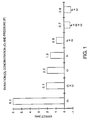
- Fig 1 there is shown a bar graph in which the results of a factorial analysis of data derived from in situ cleaning of polysulfone membranes were plotted.
- the duration of contact with the cleaning fluid is the variable with the most dominant effect.
- concentration is the next most dominant variable.
- pressure which has the least effect. Since duration and concentration are the most influential variables, and these variables define the type of flow, we believe this flow to be diffusion-controlled flow.
- the in sit u cleaning process is most preferred in particular situations where it is practical deliberately to kill no more than 20%, preferably ⁇ 10% (cell count, CFU/ml) of the bacterial population in the interest of maintaining the beneficial effects of that population.
- biocidal solution it must first permeate the macroporous wall of the membrane in which essentially no bacteria are lodged (they cannot come through the skin and intermediate transport layers of a membrane) and attack bacteria, dead and alive, randomly lodged in the biofilm to provide a random network of pores through as much of the biofilm as is left. In general, there always is some biofilm left because the time over which diffusion takes place is insufficient to remove all the biofilm even if all the bacteria are killed in the biofilm.
- biocidal solution which is incapable of diffusing through the biofilm easily will require too long a soak period and/or too long a recirculation period. Therefore the choice of biocidal solution is typically an oxidative electrolyte, and the concentration in which it is to be used, must be related to the transmembrane flux of that solution through the membrane to be cleaned and to the foulant(s) to be removed.
- oxidative electrolyte we refer to one which at least has an active anion, and preferably also an active associated cation and include such materials as the organic peroxides and hydrogen peroxide.
- Preferred biocidal solutions and the foulants for which they are generally particularly effective are listed side-by-side in Table herebelow : Cleaning solution Foulant Hydrochloric acid, HCl - pH 4 Inorganic solids, CaCO 3 2.0 wt% citric acid + NH 4 OH - pH 4 Inorganic colloids, metal, oxides, CaCO 3 NaOH - pH 11 Organics, inorganic colloids, silica 0.25 wt% HCHO followed by a detergent (with phosphate) Biological matter NaOCl with 100 ppm "active" Cl -pH 5 to 10 Organics, biological matter 1 wt% NaCl General cleaning 1 wt% oxalic acid - pH 2 to 4 Colloids, iron oxides 1 wt% NaHSO 3 - pH 5 to 6 Colloids, iron oxides 700 ppm EDTA/2500 ppm NaEDTA -pH 6 Metals, CaCO 3 , MgCO 3 ; oxide or sulphate scales
- solution is used since it is most convenient to use an aqueous biocidal solution of known concentration.
- the cleaning fluid chosen is preferably inert relative to the synthetic resinous material of the membrane though it may swell in contact with the cleaning fluid; for example, polypropylene fibers tend to be hydrolyzed with NaOCl solution, but are inert with respect to aqueous H 2 O 2 (hydrogen peroxide); and, polysulfone fibers tend to swell in contact with NaOCl solution but are otherwise inert to the solution.
- polypropylene fibers tend to be hydrolyzed with NaOCl solution, but are inert with respect to aqueous H 2 O 2 (hydrogen peroxide); and, polysulfone fibers tend to swell in contact with NaOCl solution but are otherwise inert to the solution.
- H 2 O 2 hydrogen peroxide
- polysulfone fibers tend to swell in contact with NaOCl solution but are otherwise inert to the solution.
- as little as 10 ppm of the cleaning fluid can be effective.
- a concentration no greater than 500 ppm of the active anion, e.g. OCl - , or Cl - is preferred, since higher concentrations up to 0.1% by weight of the active anion fail to provide significantly improved performance.
- the temperature of the biocidal solution as well as its concentration may be raised provided neither is deleterious to the membrane, and the increased concentration provides a justifiable effectiveness of "kill" without jeopardizing the vitality of the bacteria population.
- the fibers used in an array may be formed of any conventional organic membrane material. They are typically polymers which form an asymmetric membrane having a thin layer or "skin" on the outside or “shell side” of the fibers.
- Preferred materials for a base membrane which do not contain a repeating unit derived from acrylonitrile are polysulfones, poly(styrenes), including styrene-containing copolymers such as butadiene-styrene and styrene-vinylbenzylhalide copolymers, polycarbonates, cellulosic polymers, polypropylene, poly(vinyl chloride), poly(ethylene terephthalate), poly(vinylidene fluoride), aromatic polyamides and the like disclosed in U.S. Patent No. 4,230,463.
- the direction of the flow of feed is immaterial as the direction in which the feed enters a lumen is generally transverse to the upstanding fibers.
- a module housing one or more cartridges of wafers such as are shown in U.S. Patent No. 5,232,593 to Pedersen et al
- the flow of feed through the module is over the fibers and orthogonal thereto. It is preferred to use banks of modules constructed as disclosed in US Patent 5,248,424 (Cote et al).
- Typical hollow fiber membranes which are particularly amenable to being cleaned in situ have an i.d. in the range from 0.5 mm to 2.5 mm and have an o.d. in the range from 0.7 mm to 3.5 m m.
- the average pore cross sectional diameter in a fiber may vary widely, being in the range from about 5 ⁇ to 2000 ⁇ .
- the preferred pore diameter for separation of components in a liquid feedstream is in the range from about 10 ⁇ to 200 ⁇ .
- the length of a fiber in a skein is essentially independent of the strength of the fiber, or its diameter, because the skein is buoyed, both by bubbles of oxygen-containing gas introduced if live aerobic bacteria ar present, and the substrate in which it is deployed.
- the length of each fiber in the skein is preferably determined by the conditions under which the array is to operate.
- fibers of a skein range from 1 m to about 10 m long, depending upon dimensions of the body of substrate (depth and width) in which the array is deployed.
- the number of fibers in an array is arbitrary, typically being in the range from about 1,000 to about 10,000, and the preferred surface area for a skein in commercial service is in the range from 10 m 2 to 100 m 2 .
- the materials for the headers are most preferably either thermosetting or thermoplastic synthetic resinous materials, optionally reinforced with glass fibers, boron or graphite fibers and the like.
- Thermoplastic materials are preferred for relatively low temperature service below 100°C, these being chosen so as to be sufficiently compatible with the material of the fibers to produce a lasting, fluid-tight bond.
- Such thermoplastic materials may be crystalline, such as polyolefins, polyamides (nylon), polycarbonates and the like, semi-crystalline such as polyetherether ketone (PEEK), or substantially amorphous, such as poly(vinyl chloride) (PVC), and the like.
- Thermosetting resins are preferred for higher temperature service, and for ease of use.
- each of the fibers be secured in fluid-tight relationship within each header. This may be effected by simply not bundling the terminal portions of the fibers too tightly before potting them.
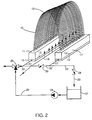
- a membrane device referred to generally by reference numeral 10, comprising an upstream header 11 and a downstream header 11', one being substantially identical to the other, upstream and downstream collection pans 15 and 15' to collect the permeate, and their respective permeate withdrawal conduits 17 and 17'.
- the purpose of the headers 11 and 11' is to pot fibers 12 in spaced apart relationship with each other in a potting resin such as an epoxy.
- the bases 13 and 13' of each header are snugly accommodated in collection pans 15 and 15' sized to the base 13 above a permeate collection zone within the pan. Air is provided through a gas distribution means 19 to maintain beneficial bacteria present in the dirty water.
- Permeate withdrawn into the lumens of the fibers collects in the pans and is discharged to a collection point as is described in the '424 patent, until the flow of permeate is about one-half of the flow at initial stable flux, at which time the flow of dirty water is shut off so that the lumens of the fibers remain filled with permeate, and the cleaning cycle is commenced.
- Conduits 21, 22 and 23 are provided as shown, connecting the lumens of fibers 12 in valved communication with the discharge of a pump 24 via a 3-way valve 25, which in one of its positions allows permeate to be withdrawn from the headers.
- Conduit 22 serves as a manifold for the collection pans 15, and an intermediate portion 22' of the conduit 22 is provided with a check valve 26 which allows biocidal solution held in cleaning tank 27 to be circulated through the lumens of fibers 12, and returned through conduit 23 to the tank 27.
- a check valve 28 is provided in conduit 23 to shut off flow of either permeate or biocidal solution to the cleaning tank.
- the 3-way valve 25 is positioned to flow biocidal solution to the upstream collection pan and enough solution is pumped from tank 27 to fill the upstream collection pan and the lumens of the fibers 12, then flow into the downstream collection pan from which it is returned to the tank 27.
- Check valve 23 is left open when cleaning solution is either circulated with pump 24 or pulsed when a pulse pump is substituted for pump 24. In those instances where it is desired to "dead end" the biocidal solution under only enough pressure to permit its diffusion-controlled flow out of the fibers, both the check valves 26 and 28 are closed.
- a module 40 having a shell 41 within which at least one cartridge 42 of wafers (only the rectangular-mesh protective screen 43 on the topmost wafer is visible) is disposed between upper and lower feed plates 44 and 44' (not visible in this view) which are longitudinally axially connected with diametrical baffles 45 and 45' which extend the length of the shell and fit in fluid-tight relationship with diagonally opposed ends 46 and 46' of the cartridge so that the permeate side of the shell is divided into two separate permeate withdrawal zones.
- the fibers in each wafer are in parallel spaced apart relationship and discharge permeate under suction conditions into both permeate withdrawal zones when dirty water is flowed axially through the center of the module as described in greater detail in US-A-5 232 593.
- biocidal solution is circulated through conduits analogous to those used in the prior embodiment, except that a 3-way valve 29 is substituted for check valves 26 and 28 in Fig 2.
- the 3-way valves indicate that permeate is being withdrawn from the module 40 through permeate withdrawal conduits 17 and 17'.
- biocidal solution is circulated through their lumens until the flux is restored to at least 70% of the initial stable flux, and preferably to more than 80%.
- permeate withdrawal in normal operation is re-commenced.
- the flow of dirty water need not be shut off. If shut off the dirty water remains in the casing outside the tube and in contact with the biofilm on the outer surface of the membrane.
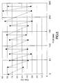
- Fig 4 there is plotted the results of a pilot plant test in which the effect of various back-flushes, each having a duration of 30 min, and carried out sequentially, was evaluated.
- the integers in brackets identify the value of the flux after the array was back-flushed with the solution/water/permeate identified, as follows: (1) 300 ppm Cl as NaOCl solution at 170 kPa (10 psig); (2) RO water at 170 kPa; (3) RO water at 170 kPa, dead-ended; (4) permeate at 170 kPa; (5) 150 ppm Cl as NaOCl solution; (6) 300 ppm Cl as NaOCl solution at 150 kPa.
- the initial flux is about 44 LMH, but the initial stable flux after a soak period of 4 hr is 38 LMH under a permeate withdrawal suction of 25.4 cm of Hg. After 72 hr the flux decreases to about 12 LMH, and the permeate being withdrawn is drained to storage.
- the piping is configured to recycle a 300 ppm Cl NaOCl solution through the lumens by positioning the 3-way valve 25, closing check valve 26 and opening check valve 28 (see Fig 3). On the scale illustrated, the 30 min period for back-flushing is not visible. Though restoration to the initial stable flux is not instantaneous (as evident from the inclination of the near-vertical line) after circulation of the biocidal solution is stopped, it is clear that the recovery is rapid.
- the pressure of 170 kPa was arrived at by trial and error for the particular fibers used, this pressure being sufficient to provide diffusion-controlled flow, the rate of which was not noticeably changed between 150 - 170 kPa. At 190 kPa the rate of flow was noticeably increased indicating flow under pressure due to developed hydraulic forces.
- FIG 5 there is plotted the results of a pilot plant test in which a frameless array analogous to that shown in Fig 2, of 1400 MF fibers each 2 meters long, having an o.d. of 2 mm, an i.d. of 1.5 mm, and pores having a nominal diameter of about 0.15 ⁇ m, the majority of which are smaller than 0.15 ⁇ m, the smallest being about 0.08 ⁇ m and the largest 0.35 ⁇ m.
- the array is fully immersed in a tank into which domestic wastewater is fed.
- the initial stable flux after a soak period of 4 hr is 78 LMH.
- FIG 6 there is plotted the results of a pilot plant test for recovering purified water from groundwater flowing into a tank in which a frameless array analogous to that shown in Fig 2, is immersed. As permeate is withdrawn, the groundwater is concentrated into an aqueous substrate. A portion of this substrate is purged either continuously or periodically, to maintain a desired concentration of contaminants in the substrate.
- the array used 110 MF fluoropolymer fibers each 2 meters long, havi an o.d. of 2 mm, an i.d. of 1.5 mm, and pores having a nominal diameter of about 0.15 ⁇ m the majority of which are smaller than 0.15 ⁇ m, the smallest being about 0.08 ⁇ m and the largest 0.35 ⁇ m.
- the array is fully immersed in a tank into which the groundwater contaminated with iron and manganese salts, is fed.
- the initial stable flux after a soak period of 4 hr is 90 LMH.
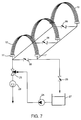
- Fig 7 is schematically illustrated the use of 3 modules of frameless arrays of fibers freely swaying in skeins above headers which are manifolded for withdrawal of permeate from the lumens, in the medium of a reservoir in which beneficial aerobic bacteria are nourished. Conduits for supplying air under the skeins are not shown. As indicated, the clearing cycles of each module may be undertaken separately, or they may be cleaned together. In each case, the flow of cleaning solution is not blocked through the skeins of fibers.
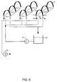
- Fig 8 is schematically illustrated another, larger use than that described in Fig 7.
- 3 banks of 3 modules each are manifolded for withdrawal of permeate from the lumens.
- the cleaning cycles of each bank may be undertaken separately, or they may be cleaned together. In each case, the flow of cleaning solution is not blocked through the skeins of fibers.
Landscapes
- Chemical & Material Sciences (AREA)
- Chemical Kinetics & Catalysis (AREA)
- Separation Using Semi-Permeable Membranes (AREA)
Applications Claiming Priority (3)
| Application Number | Priority Date | Filing Date | Title |
|---|---|---|---|
| US08/170,053 US5403479A (en) | 1993-12-20 | 1993-12-20 | In situ cleaning system for fouled membranes |
| US170053 | 1993-12-20 | ||
| PCT/CA1994/000691 WO1995017241A1 (en) | 1993-12-20 | 1994-12-19 | In situ cleaning system for fouled membranes |
Publications (2)
| Publication Number | Publication Date |
|---|---|
| EP0738180A1 EP0738180A1 (en) | 1996-10-23 |
| EP0738180B1 true EP0738180B1 (en) | 1998-08-19 |
Family
ID=22618357
Family Applications (1)
| Application Number | Title | Priority Date | Filing Date |
|---|---|---|---|
| EP95903730A Expired - Lifetime EP0738180B1 (en) | 1993-12-20 | 1994-12-19 | In situ cleaning system for fouled membranes |
Country Status (6)
| Country | Link |
|---|---|
| US (1) | US5403479A (cg-RX-API-DMAC7.html) |
| EP (1) | EP0738180B1 (cg-RX-API-DMAC7.html) |
| AU (1) | AU1269795A (cg-RX-API-DMAC7.html) |
| DE (1) | DE69412647T2 (cg-RX-API-DMAC7.html) |
| TW (1) | TW259726B (cg-RX-API-DMAC7.html) |
| WO (1) | WO1995017241A1 (cg-RX-API-DMAC7.html) |
Families Citing this family (133)
| Publication number | Priority date | Publication date | Assignee | Title |
|---|---|---|---|---|
| US5639373A (en) | 1995-08-11 | 1997-06-17 | Zenon Environmental Inc. | Vertical skein of hollow fiber membranes and method of maintaining clean fiber surfaces while filtering a substrate to withdraw a permeate |
| KR0154384B1 (ko) * | 1995-07-03 | 1998-10-15 | 박원훈 | 중공사 막을 사용하는 수처리 장치 |
| US8852438B2 (en) * | 1995-08-11 | 2014-10-07 | Zenon Technology Partnership | Membrane filtration module with adjustable header spacing |
| US20040238432A1 (en) * | 1995-08-11 | 2004-12-02 | Mailvaganam Mahendran | Membrane filtration module with adjustable header spacing |
| KR100693944B1 (ko) * | 1995-08-11 | 2007-03-12 | 제논 인바이런멘탈 인코포레이티드 | 수직한 중공사 멤브레인 다발 및 섬유 표면을 깨끗하게유지시키는 방법 |
| US7087173B2 (en) * | 1995-08-11 | 2006-08-08 | Zenon Environmental Inc. | Inverted cavity aerator for membrane module |
| FR2741280B1 (fr) * | 1995-11-22 | 1997-12-19 | Omnium Traitement Valorisa | Procede de nettoyage d'une installation de filtration du type a membranes immergees |
| EP1736234A3 (en) | 1996-12-20 | 2007-06-13 | Siemens Water Technologies Corp. | Method for scouring fouled membranes |
| US20040232076A1 (en) * | 1996-12-20 | 2004-11-25 | Fufang Zha | Scouring method |
| JP3429148B2 (ja) * | 1996-12-27 | 2003-07-22 | 株式会社荏原製作所 | 浸漬型中空糸分離膜モジュール及びその製造方法 |
| US6120688A (en) * | 1997-02-25 | 2000-09-19 | Zenon Environmental, Inc. | Portable reverse osmosis unit for producing drinking water |
| US6027572A (en) * | 1997-06-23 | 2000-02-22 | Princeton Trade And Technologt, Inc | Cleaning method for removing biofilm and debris from lines and tubing |
| US6641733B2 (en) * | 1998-09-25 | 2003-11-04 | U. S. Filter Wastewater Group, Inc. | Apparatus and method for cleaning membrane filtration modules |
| AU4986599A (en) * | 1998-07-14 | 2000-02-07 | Desalination Systems, Inc. | Cleaning fouled membranes |
| US6280626B1 (en) * | 1998-08-12 | 2001-08-28 | Mitsubishi Rayon Co., Ltd. | Membrane separator assembly and method of cleaning the assembly utilizing gas diffuser underneath the assembly |
| TWI222895B (en) | 1998-09-25 | 2004-11-01 | Usf Filtration & Separations | Apparatus and method for cleaning membrane filtration modules |
| US20040007527A1 (en) * | 1998-11-23 | 2004-01-15 | Zenon Environmental Inc. | Membrane filtration device and process |
| DE69924642T2 (de) * | 1998-11-23 | 2006-02-09 | Zenon Environmental Inc., Oakville | Wasserfiltration mittels unterwassermembranen |
| US6156200A (en) * | 1998-12-08 | 2000-12-05 | Usf Filtration & Separations Group, Inc. | Gas-scrubbed hollow fiber membrane module |
| WO2000048943A1 (en) * | 1999-02-18 | 2000-08-24 | Beall Timothy A | Reverse osmosis system with biological contamination prevention |
| US6322703B1 (en) | 1999-04-20 | 2001-11-27 | Asahi Kasei Kabushiki Kaisha | Method for purifying aqueous suspension |
| AUPP985099A0 (en) * | 1999-04-20 | 1999-05-13 | Usf Filtration And Separations Group Inc. | Membrane filtration manifold system |
| US6331251B1 (en) | 1999-06-10 | 2001-12-18 | Envirogen, Inc. | System and method for withdrawing permeate through a filter and for cleaning the filter in situ |
| US6627082B2 (en) * | 1999-06-10 | 2003-09-30 | Envirogen, Inc. | System and method for withdrawing permeate through a filter and for cleaning the filter in situ |
| WO2001008790A1 (en) * | 1999-07-29 | 2001-02-08 | Zenon Environmental Inc. | Chemical cleaning backwash for immersed filtering membranes |
| US6547968B1 (en) | 1999-07-30 | 2003-04-15 | Zenon Environmental Inc. | Pulsed backwash for immersed membranes |
| US6303035B1 (en) | 1999-07-30 | 2001-10-16 | Zenon Environmental Inc. | Immersed membrane filtration process |
| US20040007525A1 (en) * | 1999-07-30 | 2004-01-15 | Rabie Hamid R. | Maintenance cleaning for membranes |
| US20050178729A1 (en) * | 1999-07-30 | 2005-08-18 | Rabie Hamid R. | Maintenance cleaning for membranes |
| US20010052494A1 (en) * | 1999-10-25 | 2001-12-20 | Pierre Cote | Chemical cleaning backwash for normally immersed membranes |
| US6214231B1 (en) * | 1999-08-27 | 2001-04-10 | Zenon Environmental Inc. | System for operation of multiple membrane filtration assemblies |
| AUPQ680100A0 (en) * | 2000-04-10 | 2000-05-11 | Usf Filtration And Separations Group Inc. | Hollow fibre restraining system |
| US6387262B1 (en) * | 2000-06-05 | 2002-05-14 | Northwestern University | Hollow-fiber membrane biofilm reactor for autohydrogenotrophic treatment of water |
| DE10045227C1 (de) * | 2000-09-13 | 2002-02-07 | Vosenkaul Klaus | Membranfilter für die Wasseraufbereitung |
| AUPR064800A0 (en) * | 2000-10-09 | 2000-11-02 | Usf Filtration And Separations Group Inc. | Improved membrane filtration system |
| US6706171B2 (en) | 2000-10-12 | 2004-03-16 | Biochem Technology, Inc. | Systems for treating wastewater in a series of filter-containing tanks |
| AUPR094600A0 (en) * | 2000-10-23 | 2000-11-16 | Usf Filtration And Separations Group Inc. | Fibre membrane arrangement |
| AUPR143400A0 (en) * | 2000-11-13 | 2000-12-07 | Usf Filtration And Separations Group Inc. | Modified membranes |
| AUPR421501A0 (en) | 2001-04-04 | 2001-05-03 | U.S. Filter Wastewater Group, Inc. | Potting method |
| AUPR584301A0 (en) * | 2001-06-20 | 2001-07-12 | U.S. Filter Wastewater Group, Inc. | Membrane polymer compositions |
| AUPR692401A0 (en) | 2001-08-09 | 2001-08-30 | U.S. Filter Wastewater Group, Inc. | Method of cleaning membrane modules |
| AUPR774201A0 (en) * | 2001-09-18 | 2001-10-11 | U.S. Filter Wastewater Group, Inc. | High solids module |
| EP1312408B1 (en) * | 2001-11-16 | 2006-07-19 | US Filter Wastewater Group, Inc. | Method of cleaning membranes |
| AU2002357338A1 (en) * | 2002-01-09 | 2003-07-30 | Hydranautics | Methods for improving filtration performance of hollow fiber membranes |
| US7247238B2 (en) * | 2002-02-12 | 2007-07-24 | Siemens Water Technologies Corp. | Poly(ethylene chlorotrifluoroethylene) membranes |
| AUPS300602A0 (en) | 2002-06-18 | 2002-07-11 | U.S. Filter Wastewater Group, Inc. | Methods of minimising the effect of integrity loss in hollow fibre membrane modules |
| DE10237082B4 (de) * | 2002-08-09 | 2014-12-31 | Sartorius Stedim Biotech Gmbh | Verfahren und Vorrichtung zur biotechnologischen Herstellung von Wertstoffen |
| US8147699B2 (en) * | 2002-08-21 | 2012-04-03 | Hpd, Llc | Monolith filter apparatus and membrane apparatus, and method using same |
| JP2005537920A (ja) * | 2002-09-04 | 2005-12-15 | バイオラブ、インコーポレーテッド | 逆浸透メンブランの消毒 |
| ATE542593T1 (de) | 2002-10-10 | 2012-02-15 | Siemens Industry Inc | Membranfilter und rückspülverfahren dafür |
| AU2002953111A0 (en) | 2002-12-05 | 2002-12-19 | U. S. Filter Wastewater Group, Inc. | Mixing chamber |
| IL157581A (en) * | 2003-01-09 | 2004-08-31 | Ide Technologies Ltd | Direct osmosis membrane cleaning |
| DE10301860A1 (de) * | 2003-01-17 | 2004-07-29 | Puron Ag | Membrananlage und Verfahren zur permeatseitigen Reinigung dieser Anlage |
| WO2004078222A1 (en) * | 2003-03-04 | 2004-09-16 | Valspar Sourcing Inc. | Treating an electrocoat system with a biosurfactant |
| ES2308159T3 (es) * | 2003-03-05 | 2008-12-01 | Hydranautics | Dispositivo de filtracion modular de membrana sumergible que tiene elementos de membrana sustituibles. |
| US20040262209A1 (en) * | 2003-04-25 | 2004-12-30 | Hiroyuki Umezawa | Filtration apparatus |
| AU2003903507A0 (en) | 2003-07-08 | 2003-07-24 | U. S. Filter Wastewater Group, Inc. | Membrane post-treatment |
| KR101115173B1 (ko) | 2003-08-29 | 2012-02-24 | 지멘스 워터 테크놀로지스 코포레이션 | 역류 |
| SG119706A1 (en) * | 2003-09-19 | 2006-03-28 | Us Filter Wastewater Group Inc | Improved methods of cleaning membrane modules |
| US7879229B2 (en) * | 2003-10-29 | 2011-02-01 | Zenon Technology Partnership | Water treatment plant with immersed membranes |
| US8114293B2 (en) * | 2003-10-29 | 2012-02-14 | Zenon Technology Partnership | Method of operating a water treatment plant with immersed membranes |
| AU2004289373B2 (en) | 2003-11-14 | 2010-07-29 | Evoqua Water Technologies Llc | Improved module cleaning method |
| US20070051679A1 (en) * | 2004-02-27 | 2007-03-08 | Adams Nicholas W H | Water filtration using immersed membranes |
| CA2482517A1 (en) * | 2004-09-24 | 2006-03-24 | Zenon Environmental Inc. | Membrane filter cleansing process |
| WO2005092799A1 (en) | 2004-03-26 | 2005-10-06 | U.S. Filter Wastewater Group, Inc. | Process and apparatus for purifying impure water using microfiltration or ultrafiltration in combination with reverse osmosis |
| JP2007535398A (ja) | 2004-04-22 | 2007-12-06 | シーメンス ウォーター テクノロジース コーポレイション | 有機物質を消化するためのメンブレンバイオリアクタおよび処理槽を含む濾過装置ならびに廃液処理方法 |
| US7819956B2 (en) * | 2004-07-02 | 2010-10-26 | Siemens Water Technologies Corp. | Gas transfer membrane |
| ATE523240T1 (de) | 2004-07-05 | 2011-09-15 | Siemens Water Tech Corp | Hydrophile membranen |
| CN101052457B (zh) | 2004-08-20 | 2012-07-04 | 西门子工业公司 | 正方形mbr歧管系统 |
| US8790515B2 (en) | 2004-09-07 | 2014-07-29 | Evoqua Water Technologies Llc | Reduction of backwash liquid waste |
| CA2579857A1 (en) | 2004-09-14 | 2006-03-23 | Siemens Water Technologies Corp. | Membrane filtration module and cleaning process |
| EP1807181A4 (en) * | 2004-09-15 | 2009-04-22 | Siemens Water Tech Corp | CONTINUOUS ADJUSTABLE VENTILATION |
| US7591950B2 (en) | 2004-11-02 | 2009-09-22 | Siemens Water Technologies Corp. | Submerged cross-flow filtration |
| CN101084057B (zh) * | 2004-12-03 | 2013-10-23 | 西门子工业公司 | 膜的后处理方法 |
| US20060118487A1 (en) * | 2004-12-07 | 2006-06-08 | Adams Nicholas W H | Membrane filtration process |
| EP1835985B1 (en) * | 2004-12-24 | 2012-03-14 | Siemens Industry, Inc. | Cleaning in membrane filtration systems |
| JP2008525167A (ja) | 2004-12-24 | 2008-07-17 | シーメンス・ウォーター・テクノロジーズ・コーポレーション | 簡易ガス洗浄方法および当該技術分野の装置 |
| US20060191837A1 (en) * | 2005-02-28 | 2006-08-31 | Alfa Laval Corporate Ab | Permeate spacer module |
| US20060266705A1 (en) * | 2005-04-22 | 2006-11-30 | Arnold Janson | Refreshing chemicals during membrane cleaning |
| EP1885475B1 (en) * | 2005-04-29 | 2015-03-25 | Evoqua Water Technologies LLC | Chemical clean for membrane filter |
| AU2006243804B2 (en) * | 2005-04-29 | 2011-08-18 | Evoqua Water Technologies Llc | Chemical clean for membrane filter |
| US20060273038A1 (en) * | 2005-06-02 | 2006-12-07 | Syed Murtuza A | Chemical cleaning for membranes |
| NZ563980A (en) * | 2005-06-20 | 2011-07-29 | Siemens Water Tech Corp | Cross linking treatment of polymer membranes |
| EP1901835B1 (en) | 2005-07-14 | 2012-11-14 | Siemens Industry, Inc. | Monopersulfate treatment of membranes |
| DE102005035044A1 (de) * | 2005-07-27 | 2007-02-01 | Koch Membrane Systems Gmbh | Verfahren zum Rückspülen von Kapillarmembranen einer Membrananlage |
| EP1945333B1 (en) | 2005-08-22 | 2011-06-08 | Siemens Industry, Inc. | An assembly for water filtration to minimise backwash volume |
| WO2007044442A2 (en) * | 2005-10-05 | 2007-04-19 | Siemens Water Technologies Corp. | Method and system for treating wastewater |
| WO2007044345A2 (en) | 2005-10-05 | 2007-04-19 | Siemens Water Technologies Corp. | Method and apparatus for treating wastewater |
| WO2007044415A2 (en) | 2005-10-05 | 2007-04-19 | Siemens Water Technologies Corp. | Method and apparatus for treating wastewater |
| WO2007064831A1 (en) * | 2005-12-02 | 2007-06-07 | Kinetico Incorporated | Membrane flushing system |
| US7455765B2 (en) | 2006-01-25 | 2008-11-25 | Siemens Water Technologies Corp. | Wastewater treatment system and method |
| US20070289362A1 (en) * | 2006-06-19 | 2007-12-20 | David Brian Ross | Air scouring for immersed membranes |
| SG141244A1 (en) * | 2006-09-08 | 2008-04-28 | Ultra Flo Pte Ltd | Filter renewal system and a method thereof |
| WO2008051546A2 (en) | 2006-10-24 | 2008-05-02 | Siemens Water Technologies Corp. | Infiltration/inflow control for membrane bioreactor |
| US20080149570A1 (en) * | 2006-12-20 | 2008-06-26 | Zeiher E H Kelle | Method of cleaning and maintaining a membrane used with an aqueous stream |
| DE102008006501B4 (de) * | 2007-03-19 | 2013-05-16 | Sonja Lauterborn | Kombiniertes Ultraschall-Luft-Rückspülverfahren zur chemikalienfreien In- situ-Reinigung getauchter Membranen bei Rückspülung während des Betriebes |
| WO2008123972A1 (en) | 2007-04-02 | 2008-10-16 | Siemens Water Technologies Corp. | Improved infiltration/inflow control for membrane bioreactor |
| US9764288B2 (en) | 2007-04-04 | 2017-09-19 | Evoqua Water Technologies Llc | Membrane module protection |
| CN103055703B (zh) | 2007-05-29 | 2016-08-10 | 伊沃夸水处理技术有限责任公司 | 使用脉冲气提泵的膜清洗 |
| US20090242484A1 (en) | 2008-04-01 | 2009-10-01 | Ana-Mariana Urmenyi | Environmentally friendly hybrid microbiological control technologies for cooling towers |
| AU2009273775B2 (en) | 2008-07-24 | 2014-11-20 | Evoqua Water Technologies Llc | Frame system for membrane filtration modules |
| CN102123784A (zh) | 2008-08-20 | 2011-07-13 | 西门子水处理技术公司 | 改进的膜系统反洗能效 |
| WO2010142673A1 (en) | 2009-06-11 | 2010-12-16 | Siemens Water Technologies Corp. | Methods for cleaning a porous polymeric membrane and a kit for cleaning a porous polymeric membrane |
| WO2011048681A1 (ja) * | 2009-10-22 | 2011-04-28 | 旭化成ケミカルズ株式会社 | 浸漬型分離膜装置の洗浄方法、及び浸漬型分離膜装置の洗浄システム |
| CN102869432B (zh) | 2010-04-30 | 2016-02-03 | 伊沃夸水处理技术有限责任公司 | 流体流分配装置 |
| WO2012040412A1 (en) | 2010-09-24 | 2012-03-29 | Siemens Industry, Inc. | Fluid control manifold for membrane filtration system |
| JPWO2012077506A1 (ja) * | 2010-12-10 | 2014-05-19 | 東レ株式会社 | 浸漬膜エレメントの薬品洗浄方法 |
| RU2719308C2 (ru) | 2011-04-12 | 2020-04-17 | Сан Пэтент Траст | Способ кодирования движущихся изображений, устройство кодирования движущихся изображений, способ декодирования движущихся изображений, устройство декодирования движущихся изображений и устройство кодирования и декодирования движущихся изображений |
| CN103492054B (zh) * | 2011-04-25 | 2015-06-03 | 东丽株式会社 | 膜组件的洗涤方法 |
| KR102126486B1 (ko) | 2011-05-24 | 2020-06-25 | 벨로스 미디어 인터내셔널 리미티드 | 화상 부호화 방법, 화상 부호화 장치, 화상 복호 방법, 화상 복호 장치, 및, 화상 부호화 복호 장치 |
| US8910799B2 (en) | 2011-08-01 | 2014-12-16 | Enveera, Inc. | Integrated membrane system for distributed water treatment |
| CN103781533A (zh) * | 2011-09-16 | 2014-05-07 | 通用电气公司 | 改进用于膜蒸馏的膜的性能的方法 |
| SG11201401089PA (en) | 2011-09-30 | 2014-04-28 | Evoqua Water Technologies Llc | Improved manifold arrangement |
| KR20140097140A (ko) | 2011-09-30 | 2014-08-06 | 에보쿠아 워터 테크놀로지스 엘엘씨 | 아이솔레이션 밸브 |
| KR102108593B1 (ko) | 2012-06-28 | 2020-05-29 | 에보쿠아 워터 테크놀로지스 엘엘씨 | 포팅 방법 |
| JP5985914B2 (ja) * | 2012-07-23 | 2016-09-06 | 三井造船株式会社 | 膜処理装置の薬液循環の制御装置 |
| US9868834B2 (en) | 2012-09-14 | 2018-01-16 | Evoqua Water Technologies Llc | Polymer blend for membranes |
| FR2995540B1 (fr) | 2012-09-20 | 2014-11-21 | Total Sa | Unite sous-marine de traitement de l'eau et procede de nettoyage de ladite unite |
| CN104684631A (zh) | 2012-09-26 | 2015-06-03 | 伊沃夸水处理技术有限责任公司 | 膜固定设备 |
| US9962865B2 (en) | 2012-09-26 | 2018-05-08 | Evoqua Water Technologies Llc | Membrane potting methods |
| EP2900356A1 (en) | 2012-09-27 | 2015-08-05 | Evoqua Water Technologies LLC | Gas scouring apparatus for immersed membranes |
| WO2015050764A1 (en) | 2013-10-02 | 2015-04-09 | Evoqua Water Technologies Llc | A method and device for repairing a membrane filtration module |
| WO2017011068A1 (en) | 2015-07-14 | 2017-01-19 | Evoqua Water Technologies Llc | Aeration device for filtration system |
| WO2017106623A1 (en) | 2015-12-16 | 2017-06-22 | Ecolab Usa Inc. | Peroxyformic acid compositions for membrane filtration cleaning |
| EP4147574A1 (en) | 2016-04-15 | 2023-03-15 | Ecolab USA Inc. | Performic acid biofilm prevention for industrial co2 scrubbers |
| US11767501B2 (en) | 2016-05-09 | 2023-09-26 | Global Algae Technology, LLC | Biological and algae harvesting and cultivation systems and methods |
| WO2017196384A1 (en) | 2016-05-09 | 2017-11-16 | Global Algae Innovations, Inc. | Biological and algae harvesting and cultivation systems and methods |
| KR101727862B1 (ko) * | 2016-07-15 | 2017-04-17 | (주)프라임 텍 인터내쇼날 | 극세사 여과 카세트의 세정제 조성물 |
| EP3512813B1 (en) * | 2016-09-15 | 2024-11-06 | Fluence Water Israel Ltd | Containerized desalination system |
| BR112019010464B1 (pt) | 2016-12-15 | 2024-02-06 | Ecolab Usa Inc | Método para remover micro-organismos e depósitos minerais em um sistema de membrana |
| EP3628023A1 (en) * | 2017-05-08 | 2020-04-01 | Smith, Michael | System and method for preventing membrane fouling in reverse osmosis purification systems utilizing hydrodynamic cavitation |
| WO2019147856A1 (en) * | 2018-01-25 | 2019-08-01 | Johnson Jack E | Membrane and diffuser de-fouling treatment |
| CA3107770C (en) | 2018-08-16 | 2023-09-05 | Emd Millipore Corporation | Closed bioprocessing device |
Family Cites Families (14)
| Publication number | Priority date | Publication date | Assignee | Title |
|---|---|---|---|---|
| US4414113A (en) * | 1982-09-29 | 1983-11-08 | Ecodyne Corporation | Liquid purification using reverse osmosis hollow fibers |
| US4767538A (en) * | 1983-01-14 | 1988-08-30 | Baxter Travenol Laboratories, Inc. | Washing of semipermeable membrane |
| US5047154A (en) * | 1983-03-10 | 1991-09-10 | C.P.C. Engineering Company | Method and apparatus for enhancing the flux rate of cross-flow filtration systems |
| EP0160014B1 (en) * | 1983-09-30 | 1993-01-07 | Memtec Limited | Cleaning of filters |
| JPH01501046A (ja) * | 1986-09-04 | 1989-04-13 | メムテック・リミテッド | 中空繊維フィルターの洗浄方法 |
| GB8807825D0 (en) * | 1988-03-31 | 1988-05-05 | Romicon Inc | Multiple membrane filtration systems |
| US4840768A (en) * | 1988-11-14 | 1989-06-20 | The Babcock & Wilcox Company | Austenitic Fe-Cr-Ni alloy designed for oil country tubular products |
| US4865752A (en) * | 1988-12-05 | 1989-09-12 | Jacobs Albert L | Separation and filtration membranes and their regeneration |
| US5248424A (en) * | 1990-08-17 | 1993-09-28 | Zenon Environmental Inc. | Frameless array of hollow fiber membranes and method of maintaining clean fiber surfaces while filtering a substrate to withdraw a permeate |
| JP2904564B2 (ja) * | 1990-08-31 | 1999-06-14 | オルガノ株式会社 | 中空糸膜を用いる濾過塔のスクラビング方法 |
| US5132015A (en) * | 1990-10-04 | 1992-07-21 | Rohm And Haas Company | Flow control for ultra filtration systems |
| FR2668078B1 (fr) * | 1990-10-17 | 1992-12-24 | Dumez Lyonnaise Eaux | Procede pour le retrolavage de membrane tubulaires de filtration, et dispositif de mise en óoeuvre. |
| JPH04265127A (ja) * | 1991-02-20 | 1992-09-21 | Ebara Corp | 中空糸ろ過モジュール |
| DE4205826A1 (de) * | 1992-02-26 | 1993-09-02 | Zehetner Michael Dipl Ing Univ | Verfahren und vorrichtung zur reinigung von umkehrosmosegeraeten |
-
1993
- 1993-12-20 US US08/170,053 patent/US5403479A/en not_active Expired - Fee Related
-
1994
- 1994-12-19 WO PCT/CA1994/000691 patent/WO1995017241A1/en not_active Ceased
- 1994-12-19 DE DE69412647T patent/DE69412647T2/de not_active Expired - Fee Related
- 1994-12-19 AU AU12697/95A patent/AU1269795A/en not_active Abandoned
- 1994-12-19 EP EP95903730A patent/EP0738180B1/en not_active Expired - Lifetime
-
1995
- 1995-01-25 TW TW084100631A patent/TW259726B/zh active
Also Published As
| Publication number | Publication date |
|---|---|
| WO1995017241A1 (en) | 1995-06-29 |
| DE69412647D1 (de) | 1998-09-24 |
| TW259726B (cg-RX-API-DMAC7.html) | 1995-10-11 |
| DE69412647T2 (de) | 1999-04-01 |
| EP0738180A1 (en) | 1996-10-23 |
| AU1269795A (en) | 1995-07-10 |
| US5403479A (en) | 1995-04-04 |
Similar Documents
| Publication | Publication Date | Title |
|---|---|---|
| EP0738180B1 (en) | In situ cleaning system for fouled membranes | |
| US6547968B1 (en) | Pulsed backwash for immersed membranes | |
| US9675938B2 (en) | Chemical clean for membrane filter | |
| US6303035B1 (en) | Immersed membrane filtration process | |
| US7070695B2 (en) | Ultrafiltration and microfiltration module and system | |
| US7585411B2 (en) | Low pressure filtration | |
| US20080203019A1 (en) | Membrane batch filtration process | |
| US20030146153A1 (en) | Chemical cleaning backwash for normally immersed membranes | |
| US20060065596A1 (en) | Membrane filter cleansing process | |
| WO2001008790A1 (en) | Chemical cleaning backwash for immersed filtering membranes | |
| EP2276705B1 (en) | Environmentally friendly hybrid microbiological control technologies for cooling towers | |
| US20170274325A1 (en) | Water treatment method | |
| NZ228510A (en) | Membrane separation system: membranes partially immersed in permeate | |
| WO2005082498A1 (en) | Water filtration using immersed membranes | |
| WO2019183221A1 (en) | Chemical cleaning for membrane filters | |
| US20050178729A1 (en) | Maintenance cleaning for membranes | |
| Doyen et al. | Methodology for accelerated pre-selection of UF type of membranes for large scale applications | |
| US20210146312A1 (en) | Process for cleaning a membrane comprising drying the membrane | |
| AU2006243804B2 (en) | Chemical clean for membrane filter | |
| JP2002028456A (ja) | スパイラル型膜モジュールを用いた処理システムおよびその運転方法 | |
| US20060266705A1 (en) | Refreshing chemicals during membrane cleaning | |
| Doyen et al. | UF as an alternative pretreatment step for producing drinking water | |
| JP4583557B2 (ja) | スパイラル型膜エレメントおよびスパイラル型膜モジュールの運転方法および洗浄方法 | |
| CA2279087A1 (en) | Maintenance cleaning for membranes | |
| EP1718398A1 (en) | Water filtration using immersed membranes |
Legal Events
| Date | Code | Title | Description |
|---|---|---|---|
| PUAI | Public reference made under article 153(3) epc to a published international application that has entered the european phase |
Free format text: ORIGINAL CODE: 0009012 |
|
| 17P | Request for examination filed |
Effective date: 19960705 |
|
| AK | Designated contracting states |
Kind code of ref document: A1 Designated state(s): DE FR GB IT NL |
|
| 17Q | First examination report despatched |
Effective date: 19961031 |
|
| GRAG | Despatch of communication of intention to grant |
Free format text: ORIGINAL CODE: EPIDOS AGRA |
|
| GRAG | Despatch of communication of intention to grant |
Free format text: ORIGINAL CODE: EPIDOS AGRA |
|
| GRAH | Despatch of communication of intention to grant a patent |
Free format text: ORIGINAL CODE: EPIDOS IGRA |
|
| GRAH | Despatch of communication of intention to grant a patent |
Free format text: ORIGINAL CODE: EPIDOS IGRA |
|
| GRAA | (expected) grant |
Free format text: ORIGINAL CODE: 0009210 |
|
| AK | Designated contracting states |
Kind code of ref document: B1 Designated state(s): DE FR GB IT NL |
|
| REF | Corresponds to: |
Ref document number: 69412647 Country of ref document: DE Date of ref document: 19980924 |
|
| ET | Fr: translation filed | ||
| PLBE | No opposition filed within time limit |
Free format text: ORIGINAL CODE: 0009261 |
|
| STAA | Information on the status of an ep patent application or granted ep patent |
Free format text: STATUS: NO OPPOSITION FILED WITHIN TIME LIMIT |
|
| 26N | No opposition filed | ||
| REG | Reference to a national code |
Ref country code: GB Ref legal event code: IF02 |
|
| PGFP | Annual fee paid to national office [announced via postgrant information from national office to epo] |
Ref country code: NL Payment date: 20051204 Year of fee payment: 12 |
|
| PGFP | Annual fee paid to national office [announced via postgrant information from national office to epo] |
Ref country code: FR Payment date: 20051208 Year of fee payment: 12 |
|
| PGFP | Annual fee paid to national office [announced via postgrant information from national office to epo] |
Ref country code: GB Payment date: 20051214 Year of fee payment: 12 |
|
| PGFP | Annual fee paid to national office [announced via postgrant information from national office to epo] |
Ref country code: DE Payment date: 20051215 Year of fee payment: 12 |
|
| PGFP | Annual fee paid to national office [announced via postgrant information from national office to epo] |
Ref country code: IT Payment date: 20061231 Year of fee payment: 13 |
|
| REG | Reference to a national code |
Ref country code: GB Ref legal event code: 732E |
|
| NLS | Nl: assignments of ep-patents |
Owner name: ZENON TECHNOLOGY PARTNERSHIP Effective date: 20061206 |
|
| PG25 | Lapsed in a contracting state [announced via postgrant information from national office to epo] |
Ref country code: NL Free format text: LAPSE BECAUSE OF NON-PAYMENT OF DUE FEES Effective date: 20070701 |
|
| PG25 | Lapsed in a contracting state [announced via postgrant information from national office to epo] |
Ref country code: DE Free format text: LAPSE BECAUSE OF NON-PAYMENT OF DUE FEES Effective date: 20070703 |
|
| GBPC | Gb: european patent ceased through non-payment of renewal fee |
Effective date: 20061219 |
|
| NLV4 | Nl: lapsed or anulled due to non-payment of the annual fee |
Effective date: 20070701 |
|
| REG | Reference to a national code |
Ref country code: FR Ref legal event code: ST Effective date: 20070831 |
|
| REG | Reference to a national code |
Ref country code: FR Ref legal event code: TP |
|
| PG25 | Lapsed in a contracting state [announced via postgrant information from national office to epo] |
Ref country code: GB Free format text: LAPSE BECAUSE OF NON-PAYMENT OF DUE FEES Effective date: 20061219 |
|
| PG25 | Lapsed in a contracting state [announced via postgrant information from national office to epo] |
Ref country code: FR Free format text: LAPSE BECAUSE OF NON-PAYMENT OF DUE FEES Effective date: 20070102 |
|
| PG25 | Lapsed in a contracting state [announced via postgrant information from national office to epo] |
Ref country code: IT Free format text: LAPSE BECAUSE OF NON-PAYMENT OF DUE FEES Effective date: 20071219 |