EP0737873A2 - Dispersionsgesteuerter optischer Wellenleiter - Google Patents
Dispersionsgesteuerter optischer Wellenleiter Download PDFInfo
- Publication number
- EP0737873A2 EP0737873A2 EP96105573A EP96105573A EP0737873A2 EP 0737873 A2 EP0737873 A2 EP 0737873A2 EP 96105573 A EP96105573 A EP 96105573A EP 96105573 A EP96105573 A EP 96105573A EP 0737873 A2 EP0737873 A2 EP 0737873A2
- Authority
- EP
- European Patent Office
- Prior art keywords
- diameter
- core
- length
- preform
- region
- Prior art date
- Legal status (The legal status is an assumption and is not a legal conclusion. Google has not performed a legal analysis and makes no representation as to the accuracy of the status listed.)
- Granted
Links
Images


Classifications
-
- G—PHYSICS
- G02—OPTICS
- G02B—OPTICAL ELEMENTS, SYSTEMS OR APPARATUS
- G02B6/00—Light guides; Structural details of arrangements comprising light guides and other optical elements, e.g. couplings
- G02B6/02—Optical fibres with cladding with or without a coating
- G02B6/028—Optical fibres with cladding with or without a coating with core or cladding having graded refractive index
- G02B6/0281—Graded index region forming part of the central core segment, e.g. alpha profile, triangular, trapezoidal core
-
- C—CHEMISTRY; METALLURGY
- C03—GLASS; MINERAL OR SLAG WOOL
- C03B—MANUFACTURE, SHAPING, OR SUPPLEMENTARY PROCESSES
- C03B37/00—Manufacture or treatment of flakes, fibres, or filaments from softened glass, minerals, or slags
- C03B37/01—Manufacture of glass fibres or filaments
- C03B37/012—Manufacture of preforms for drawing fibres or filaments
- C03B37/01205—Manufacture of preforms for drawing fibres or filaments starting from tubes, rods, fibres or filaments
- C03B37/01211—Manufacture of preforms for drawing fibres or filaments starting from tubes, rods, fibres or filaments by inserting one or more rods or tubes into a tube
-
- C—CHEMISTRY; METALLURGY
- C03—GLASS; MINERAL OR SLAG WOOL
- C03B—MANUFACTURE, SHAPING, OR SUPPLEMENTARY PROCESSES
- C03B37/00—Manufacture or treatment of flakes, fibres, or filaments from softened glass, minerals, or slags
- C03B37/01—Manufacture of glass fibres or filaments
- C03B37/012—Manufacture of preforms for drawing fibres or filaments
- C03B37/01205—Manufacture of preforms for drawing fibres or filaments starting from tubes, rods, fibres or filaments
- C03B37/01225—Means for changing or stabilising the shape, e.g. diameter, of tubes or rods in general, e.g. collapsing
- C03B37/01228—Removal of preform material
-
- C—CHEMISTRY; METALLURGY
- C03—GLASS; MINERAL OR SLAG WOOL
- C03B—MANUFACTURE, SHAPING, OR SUPPLEMENTARY PROCESSES
- C03B37/00—Manufacture or treatment of flakes, fibres, or filaments from softened glass, minerals, or slags
- C03B37/01—Manufacture of glass fibres or filaments
- C03B37/012—Manufacture of preforms for drawing fibres or filaments
- C03B37/01205—Manufacture of preforms for drawing fibres or filaments starting from tubes, rods, fibres or filaments
- C03B37/01225—Means for changing or stabilising the shape, e.g. diameter, of tubes or rods in general, e.g. collapsing
- C03B37/0124—Means for reducing the diameter of rods or tubes by drawing, e.g. for preform draw-down
-
- C—CHEMISTRY; METALLURGY
- C03—GLASS; MINERAL OR SLAG WOOL
- C03B—MANUFACTURE, SHAPING, OR SUPPLEMENTARY PROCESSES
- C03B37/00—Manufacture or treatment of flakes, fibres, or filaments from softened glass, minerals, or slags
- C03B37/01—Manufacture of glass fibres or filaments
- C03B37/012—Manufacture of preforms for drawing fibres or filaments
- C03B37/01205—Manufacture of preforms for drawing fibres or filaments starting from tubes, rods, fibres or filaments
- C03B37/01225—Means for changing or stabilising the shape, e.g. diameter, of tubes or rods in general, e.g. collapsing
- C03B37/01254—Means for changing or stabilising the shape, e.g. diameter, of tubes or rods in general, e.g. collapsing by expanding radially, e.g. by forcing a mandrel through or axial pressing a tube or rod
-
- C—CHEMISTRY; METALLURGY
- C03—GLASS; MINERAL OR SLAG WOOL
- C03B—MANUFACTURE, SHAPING, OR SUPPLEMENTARY PROCESSES
- C03B37/00—Manufacture or treatment of flakes, fibres, or filaments from softened glass, minerals, or slags
- C03B37/01—Manufacture of glass fibres or filaments
- C03B37/012—Manufacture of preforms for drawing fibres or filaments
- C03B37/01205—Manufacture of preforms for drawing fibres or filaments starting from tubes, rods, fibres or filaments
- C03B37/01225—Means for changing or stabilising the shape, e.g. diameter, of tubes or rods in general, e.g. collapsing
- C03B37/01257—Heating devices therefor
-
- C—CHEMISTRY; METALLURGY
- C03—GLASS; MINERAL OR SLAG WOOL
- C03B—MANUFACTURE, SHAPING, OR SUPPLEMENTARY PROCESSES
- C03B37/00—Manufacture or treatment of flakes, fibres, or filaments from softened glass, minerals, or slags
- C03B37/01—Manufacture of glass fibres or filaments
- C03B37/012—Manufacture of preforms for drawing fibres or filaments
- C03B37/014—Manufacture of preforms for drawing fibres or filaments made entirely or partially by chemical means, e.g. vapour phase deposition of bulk porous glass either by outside vapour deposition [OVD], or by outside vapour phase oxidation [OVPO] or by vapour axial deposition [VAD]
- C03B37/01413—Reactant delivery systems
-
- C—CHEMISTRY; METALLURGY
- C03—GLASS; MINERAL OR SLAG WOOL
- C03B—MANUFACTURE, SHAPING, OR SUPPLEMENTARY PROCESSES
- C03B37/00—Manufacture or treatment of flakes, fibres, or filaments from softened glass, minerals, or slags
- C03B37/01—Manufacture of glass fibres or filaments
- C03B37/012—Manufacture of preforms for drawing fibres or filaments
- C03B37/014—Manufacture of preforms for drawing fibres or filaments made entirely or partially by chemical means, e.g. vapour phase deposition of bulk porous glass either by outside vapour deposition [OVD], or by outside vapour phase oxidation [OVPO] or by vapour axial deposition [VAD]
- C03B37/01466—Means for changing or stabilising the diameter or form of tubes or rods
-
- C—CHEMISTRY; METALLURGY
- C03—GLASS; MINERAL OR SLAG WOOL
- C03B—MANUFACTURE, SHAPING, OR SUPPLEMENTARY PROCESSES
- C03B37/00—Manufacture or treatment of flakes, fibres, or filaments from softened glass, minerals, or slags
- C03B37/01—Manufacture of glass fibres or filaments
- C03B37/012—Manufacture of preforms for drawing fibres or filaments
- C03B37/014—Manufacture of preforms for drawing fibres or filaments made entirely or partially by chemical means, e.g. vapour phase deposition of bulk porous glass either by outside vapour deposition [OVD], or by outside vapour phase oxidation [OVPO] or by vapour axial deposition [VAD]
- C03B37/0148—Means for heating preforms during or immediately prior to deposition
-
- C—CHEMISTRY; METALLURGY
- C03—GLASS; MINERAL OR SLAG WOOL
- C03B—MANUFACTURE, SHAPING, OR SUPPLEMENTARY PROCESSES
- C03B37/00—Manufacture or treatment of flakes, fibres, or filaments from softened glass, minerals, or slags
- C03B37/01—Manufacture of glass fibres or filaments
- C03B37/012—Manufacture of preforms for drawing fibres or filaments
- C03B37/014—Manufacture of preforms for drawing fibres or filaments made entirely or partially by chemical means, e.g. vapour phase deposition of bulk porous glass either by outside vapour deposition [OVD], or by outside vapour phase oxidation [OVPO] or by vapour axial deposition [VAD]
- C03B37/01486—Means for supporting, rotating or translating the preforms being formed, e.g. lathes
- C03B37/01493—Deposition substrates, e.g. targets, mandrels, start rods or tubes
-
- C—CHEMISTRY; METALLURGY
- C03—GLASS; MINERAL OR SLAG WOOL
- C03B—MANUFACTURE, SHAPING, OR SUPPLEMENTARY PROCESSES
- C03B37/00—Manufacture or treatment of flakes, fibres, or filaments from softened glass, minerals, or slags
- C03B37/01—Manufacture of glass fibres or filaments
- C03B37/02—Manufacture of glass fibres or filaments by drawing or extruding, e.g. direct drawing of molten glass from nozzles; Cooling fins therefor
- C03B37/025—Manufacture of glass fibres or filaments by drawing or extruding, e.g. direct drawing of molten glass from nozzles; Cooling fins therefor from reheated softened tubes, rods, fibres or filaments, e.g. drawing fibres from preforms
- C03B37/027—Fibres composed of different sorts of glass, e.g. glass optical fibres
-
- C—CHEMISTRY; METALLURGY
- C03—GLASS; MINERAL OR SLAG WOOL
- C03C—CHEMICAL COMPOSITION OF GLASSES, GLAZES OR VITREOUS ENAMELS; SURFACE TREATMENT OF GLASS; SURFACE TREATMENT OF FIBRES OR FILAMENTS MADE FROM GLASS, MINERALS OR SLAGS; JOINING GLASS TO GLASS OR OTHER MATERIALS
- C03C25/00—Surface treatment of fibres or filaments made from glass, minerals or slags
- C03C25/62—Surface treatment of fibres or filaments made from glass, minerals or slags by application of electric or wave energy; by particle radiation or ion implantation
- C03C25/6206—Electromagnetic waves
- C03C25/6226—Ultraviolet
-
- G—PHYSICS
- G02—OPTICS
- G02B—OPTICAL ELEMENTS, SYSTEMS OR APPARATUS
- G02B6/00—Light guides; Structural details of arrangements comprising light guides and other optical elements, e.g. couplings
- G02B6/02—Optical fibres with cladding with or without a coating
- G02B6/02214—Optical fibres with cladding with or without a coating tailored to obtain the desired dispersion, e.g. dispersion shifted, dispersion flattened
- G02B6/02219—Characterised by the wavelength dispersion properties in the silica low loss window around 1550 nm, i.e. S, C, L and U bands from 1460-1675 nm
- G02B6/02247—Dispersion varying along the longitudinal direction, e.g. dispersion managed fibre
-
- C—CHEMISTRY; METALLURGY
- C03—GLASS; MINERAL OR SLAG WOOL
- C03B—MANUFACTURE, SHAPING, OR SUPPLEMENTARY PROCESSES
- C03B2203/00—Fibre product details, e.g. structure, shape
- C03B2203/10—Internal structure or shape details
- C03B2203/18—Axial perturbations, e.g. in refractive index or composition
- C03B2203/20—Axial perturbations, e.g. in refractive index or composition helical
-
- C—CHEMISTRY; METALLURGY
- C03—GLASS; MINERAL OR SLAG WOOL
- C03B—MANUFACTURE, SHAPING, OR SUPPLEMENTARY PROCESSES
- C03B2203/00—Fibre product details, e.g. structure, shape
- C03B2203/10—Internal structure or shape details
- C03B2203/22—Radial profile of refractive index, composition or softening point
- C03B2203/24—Single mode [SM or monomode]
-
- C—CHEMISTRY; METALLURGY
- C03—GLASS; MINERAL OR SLAG WOOL
- C03B—MANUFACTURE, SHAPING, OR SUPPLEMENTARY PROCESSES
- C03B2203/00—Fibre product details, e.g. structure, shape
- C03B2203/36—Dispersion modified fibres, e.g. wavelength or polarisation shifted, flattened or compensating fibres (DSF, DFF, DCF)
-
- C—CHEMISTRY; METALLURGY
- C03—GLASS; MINERAL OR SLAG WOOL
- C03C—CHEMICAL COMPOSITION OF GLASSES, GLAZES OR VITREOUS ENAMELS; SURFACE TREATMENT OF GLASS; SURFACE TREATMENT OF FIBRES OR FILAMENTS MADE FROM GLASS, MINERALS OR SLAGS; JOINING GLASS TO GLASS OR OTHER MATERIALS
- C03C2218/00—Methods for coating glass
- C03C2218/30—Aspects of methods for coating glass not covered above
- C03C2218/31—Pre-treatment
Definitions
- the invention is directed to a dispersion managed (DM) single-mode optical waveguide fiber and a method for making the inventive fiber.
- DM dispersion managed
- One strategy proposed to overcome this dilemma is to construct a system using cabled waveguide fiber lengths some of which have a positive total dispersion and some of which have a negative total dispersion. If the length weighted average of dispersion for all the cable segments is close to zero, the regenerator spacing can be large. However, the signal essentially never passes through a waveguide length where the dispersion is close to zero, so that four wave mixing is prevented.
- each link between regenerators must be tailored to give the required length weighted average of dispersion. Maintaining cable dispersion identity from cabling plant through to installation is an undesirable added task and source of error. Further, the need to provide not only the proper dispersion, but also the proper length of cable having that dispersion, increases the difficulty of manufacture and leads to increased system cost. A further problem arises when one considers the need for replacement cables.
- the present invention overcomes these problems by making each individual fiber a self contained dispersion managed system.
- the cabled waveguide fibers all have essentially identical dispersion product characteristics, and there is no need to assign a particular set of cables to a particular part of the system.
- Power penalty due to four wave mixing is essentially eliminated, or reduced to a pre-selected level, while total link dispersion is held to a pre-selected value, which may be a value substantially equal to zero.
- phase mismatch is proportional to the dispersion product.
- accumulated phase mismatch is proportional to the sum of dispersion products.
- FIGS. 6 - 7 may be best understood by regarding them as illustrative of the relation of phase mismatch to total dispersion and oscillation length.
- FIGS. 6 - 7 show the dependence of power penalty on phase mismatch, where phase mismatch has been expressed in terms of distinct measurable waveguide fiber characteristics, i.e., total dispersion and oscillation length.
- the present invention meets the need for a waveguide fiber length wherein total dispersion product is controlled to a pre-selected value which meets a system link requirement.
- Each waveguide fiber is interchangeable with any other waveguide fiber designed for that system link.
- a first aspect of the invention is a single-mode waveguide fiber having a core region surrounded by a cladding layer.
- the core region is characterized by a refractive index profile, which is the expression of the refractive index at each point along the core radius.
- a refractive index profile which is the expression of the refractive index at each point along the core radius.
- the core refractive index profile In order to guide light in the core region, at least a part of the core refractive index profile must be greater than the clad index.
- the clad has a substantially flat index, although some advantageous designs have been found wherein the clad layer has a non-constant profile.
- the dispersion of the inventive fiber is made to vary between a range of positive values and a range of negative values along the waveguide length.
- the dispersion product, expressed as ps/nm, of a particular length, l, is the product (D ps/nm-km *l km) .
- a positive number of ps/nm will cancel an equal negative number of ps/nm.
- the dispersion associated with a length l i may vary from point to point along l i . That is, the dispersion D i lies within a pre-determined range of dispersions, but may vary from point to point along l i .
- l i is made up of segments dl i over which the associated total dispersion D i is essentially constant. Then the sum of products dl i * D i characterizes the dispersion product contribution of l i . Note that, in the limit where dl i approaches zero, the sum of products dl i * D i is simply the integral of dl i * D i over the length l i . If the dispersion is essentially constant over sub-length l i , then the sum of products is simply l i * D i .
- the dispersion of the overall waveguide fiber length is managed by controlling the dispersion D i of each segment dl i , so that the sum of the products D i * dl i is equal to a pre-selected value appropriate to a particular system design.
- the sum of products is controlled to a pre-selected value over a wavelength range wherein signals may be multiplexed.
- the wavelength range in the low attenuation window from about 1525 nm to 1565 nm may be advantageously chosen.
- a preferred embodiment would have the sum of products targeted at zero over that range of wavelengths.
- the D i magnitudes are held above 0.5 ps/nm-km to substantially prevent four wave mixing and below about 20 ps/nm-km so that overly large swings in the waveguide fiber parameters are not required.
- the length over which a given total dispersion persists is generally greater than about 0.1 km. This lower length limit reduces the power penalty, (see FIG. 7 ), and simplifies the manufacturing process.
- the period of a DM single-mode waveguide is defined as a first length having a total dispersion which is within a first range, plus a second length having a dispersion which is in a second range, wherein the first and second ranges are of opposite sign, plus a length over which the dispersion makes a transition between the first and second range.
- These three lengths need not be adjacent, because the quantity being controlled is the sum of D * dl products over an entire fiber length. However, for ease of process control, the three lengths are generally arranged as a first length, an adjacent transition length, followed by a second length adjacent the transition length.
- the part of the transition length which has an associated total dispersion less than about 0.5 ps/nm-km as short as possible, preferably less than about 500 meters per transition and preferably no more than 10% of the period.
- the dispersion of a waveguide length can be changed by a plurality of methods including varying waveguide geometry, waveguide refractive index, waveguide refractive index profile, or waveguide composition.
- a core preform made by any of the processes known to those of ordinary skill in the art, may be processed to have sections of reduced diameter. The reduction can be done by any of several methods such as heating and stretching one or more sections of the preform or by removing annular regions of the preform by a mechanical technique such as grinding and polishing, a chemical technique such as acid etching and polishing, or an energy bombardment technique such as laser ablation.
- the resulting core preform is then overcladded, by any of several methods, including soot deposition or use of overcladding tubes, to form a draw blank or preform having a uniform, substantially cylindrical outer surface.
- a core preform is processed to have sections of increased diameter.
- the core preform can be heated, and regions of the preform on opposite sides of the heated region can be traversed toward the heated region to enlarge or bulge the heated region.
- the resulting core preform is then overcladded to form a draw preform.
- the waveguide core radius will be reduced over lengths corresponding to the reduced radius lengths in the core preform.
- a diameter reduction of about 5 % to 25 % is sufficient to produce the desired positive to negative dispersion variation.
- the 25 % reduction would be needed only in cases where the absolute value of total dispersion is about 20 ps/nm-km.
- a range of radii variation of 5 % to 10 % is, in general, sufficient for most applications.
- the quantity controlled is the sum of products D i * dl i and D j * dl j , where D i is a total dispersion corresponding to a reduced radius r i , which lies within a first range of values, and D j is a total dispersion corresponding to an unreduced radius r j which falls within a second range of values.
- D i and D j are of different algebraic sign in the operating wavelength range.
- the core diameter variations may also be obtained by reducing segments of the diameter of a draw preform or blank, having a substantially uniform diameter core portion, and then drawing the preform to a waveguide fiber having a uniform outer diameter.
- the waveguide core will have segments of decreased diameter corresponding to draw preform segments for which the diameter was not reduced.
- the refractive index of the fiber core is varied along the waveguide length.
- the refractive index may be changed by irradiating the fiber with radiation in the electromagnetic spectrum, or bombarding the waveguide with sub-atomic particles such as electrons, alpha particles or neutrons. Each particle is characterized by its corresponding DeBroglie wavelength. One may thus describe particle bombardment as irradiation with a particular DeBroglie wavelength.
- a preferred way to cause a variation in core index is to irradiate the waveguide fiber with ultraviolet light. Due to the nature of the polymer coating materials used to protect the waveguide fiber, the ultraviolet irradiation is done after the fiber has passed out of the hot zone of the furnace, and before it has received a polymer coating. An index difference of as low as 5 x 10 -6 can serve to limit four wave mixing. An index difference greater than about 1.0 x 10 -3 is preferred.
- the varying refractive index produces a varying total dispersion which allows the sum of products of D i * dl i and D j * dl j to be controlled.
- D i is a total dispersion corresponding to a first refractive index range.
- D j is a total dispersion corresponding to a second refractive index range.
- D i and D j are of different algebraic sign.
- a particular set of index profiles which provides the properties necessary to the inventive waveguide, are those having a core region which includes a central portion, having a refractive index profile, and at least one annular portion, surrounding the central portion having a different refractive index profile.
- Optical fibers having this type of profile are referred to as segmented core fibers.
- the term ⁇ is defined as (n 1 2 - n 2 2 )/2n 1 2 , where n 1 is the maximum refractive index of a core region and n 2 is the refractive index of the clad glass
- the index profile includes an essentially constant central portion, having a refractive index substantially equal to the clad glass refractive index and the adjacent annular index portion is a rounded step index.
- an index profile having a constant central region and one annular rounded step index portion is preferred.
- the preferred embodiment of this simple index profile has a maximum index % ⁇ of about 1 % and a ratio a 1 /a of about 0.5, where a 1 and a are defined in of FIG. 4 .
- Another aspect of the invention is a single-mode optical waveguide having a number of sub-lengths, l i , which are made up of segments, dl i , which have respective essentially constant associated dispersions, D i , where the zeros of dispersion of the D i are within a first wavelength range.
- the remaining sub-lengths, l j which together with the l i and the transition lengths, make up the waveguide fiber length, are made up of segments dl j , which have respective essentially constant associated dispersions D j , and the dispersion zeros of the D j are within a second wavelength range which is disjoint from the first wavelength range.
- disjoint The common meaning of the term disjoint is that the two ranges have no values in common.
- the lengths and dispersions are chosen so that the algebraic sum of products dl i * D i and dl j * D j is a pre-selected value over a pre-determined wavelength range.
- a preferred pre-determined system operating range is about 1525 nm to 1565 nm.
- the first range for dispersion zeros is about 1570 nm to 1680 nm, and the second range is about 1480 nm to 1535 nm.
- the communication signals will substantially always travel in a waveguide fiber of non-zero dispersion, for example a total dispersion not less than about 0.5 ps/nm-km, thereby substantially preventing four wave mixing.
- the overall system total dispersion may be held essentially at zero, so that little or no signal degradation occurs due to total dispersion, i.e., material plus waveguide dispersion.
- Yet another aspect of the invention is a method for making a DM waveguide fiber.
- a core preform is prepared having at least one sub-length of reduced diameter relative to the rest of the core preform.
- a clad layer is applied to provide a draw preform.
- the draw preform is then drawn into waveguide fiber having a substantially constant outer diameter. In keeping with the nominal specifications, the waveguide fiber is substantially free of voids.
- the core of this waveguide will have a sub-length of reduced diameter corresponding to the preform sub-length of reduced diameter.
- the number, longitudinal extent and depth of the sub-lengths of reduced diameter are chosen so that the sum of the total dispersion times sub-length products equals a pre-selected value over a predetermined wavelength range.
- the sub-length is made up of segments each having an associated, essentially constant, total dispersion and a characteristic total dispersion times length product.
- An alternative process for introducing diameter variations is the reduction of the diameter of at least one sub-length of the draw blank, which is characterized as having a substantially uniform radial core dimension. Drawing the waveguide to a uniform diameter will again produce a core having diameter fluctuations. In this case the waveguide core diameter will be smaller in the corresponding draw preform sub-lengths which are not reduced in diameter.
- the diameter reduction of either the core preform or draw preform may be carried out using any of several techniques known to those of ordinary skill in the art. These include the series techniques, grinding and polishing, etching and polishing or heating and stretching.
- core diameter variations can be introduced into the core preform by heating sections of the core preform and urging portions of the core preform on opposite sides of the heated section toward the heated section to cause it to bulge.
- the amount of the reduction is preferably in the range of about 5 % to 25 % of the unreduced core diameter. As stated above a range of 5 % to 10 % is usually sufficient.
- the sub-lengths of reduced diameter are evenly spaced along the core or draw preform to produce in the waveguide pairs of reduced and unreduced waveguide fiber sub-lengths, which are joined by a transition length over which the diameter changes from reduced to unreduced size, or vice versa. If the entire waveguide length is made up of such pairs, the overall total dispersion can be readily be targeted at zero.
- the overall dispersion target may also be a value other than zero.
- the entire waveguide fiber length is formed of a number of sub-length pairs whose dispersions essentially cancel and an additional sub-length designed to have the targeted or pre-selected dispersion times length value.
- Another aspect of the invention is a method of managing dispersion over a length of single-mode waveguide fiber, wherein the refractive index profile is increased, over at least one sub-length, by means of ultraviolet radiation so that a difference in total dispersion exists between irradiated and un-irradiated sub-lengths.
- the irradiating step is advantageously carried out after drawing but before coating of the waveguide. As mentioned above an index difference greater than about 1.0 x 10 -3 is preferred.
- An irradiation scheme effective to reduce power loss due to four wave mixing is one wherein at least one pulse of ultraviolet light, having an energy flux of about 100 mJ/cm 2 , delivered over a time in the range of about 10 to 20 ns, and, having a spot size of about 1 cm 2 , is incident upon the fiber. That is, sufficient refractive index variation is produced in the waveguide fiber to reduce signal power loss due to four wave mixing.
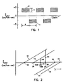
- FIG. 1 is an illustration of total dispersion varying along the waveguide fiber length.
- FIG. 2 shows how the zero dispersion of a waveguide fiber may vary to maintain total dispersion of the waveguide within a pre-selected range over a pre-determined wavelength window.
- FIG. 3 is an illustration of a waveguide fiber having a bi-modal waveguide dispersion over a pre-selected wavelength range.
- FIG. 4 is a chart of % index delta vs. radius for a simple design which approximates a bi-modal waveguide dispersion.
- FIG. 5a is a chart illustrating the power penalty vs. input power for a system comprised of particular waveguide sub-lengths having a low total dispersion magnitude.
- FIG. 5b is a chart illustrating the power penalty vs. input power for a system comprised of particular waveguide sub-lengths having a higher total dispersion magnitude.
- FIG. 6 is a chart of total dispersion vs. power penalty.
- FIG. 7 is a chart of dispersion variation period length vs. power penalty.
- FIG. 8 is a chart of transition region length vs. power penalty.
- FIG. 9 is a schematic of an apparatus for drawing a fiber and irradiating the fiber before applying a protective coating.
- FIG. 10a illustrates a longitudinal section of a core preform having length sections of reduced diameter.
- FIG. 10b illustrates the application of cladding glass particles to a core preform.
- FIG. 10c shows undulations that can exist in the surface of the draw blank as a result of diameter variations in the core preform.
- FIG. 10d shows a longitudinal section of the core preform of FIG. 10a with an overclad layer having a cylindrical outer surface.
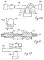
- FIG. 11a illustrates a method of periodically reducing the diameter of sections of a core preform.
- FIG. 11b is a temperature profile of the burner flame of FIG. 11a .
- FIG. 12 is an enlarged cross-sectional view of the core preform of F IG. 11a .
- FIG. 13 illustrates the cooling of regions of a core preform adjacent regions that are to be heated and stretched.
- FIG. 14 illustrates a device for confining the burner flame to a narrow section of the core preform.
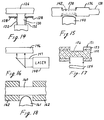
- FIG. 15 shows the heating of a slotted region of a core preform.
- FIG. 16 shows the heating of a core preform with a laser beam.
- FIG. 17 shows that a laser beam can be used for machining slots in a core preform.
- FIG. 18 illustrates the use of heat conducting sleeves.
- FIG. 19 illustrates that the core preform can be heated and bulged to periodically form regions of different diameter.
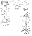
- FIGS. 20-21 illustrate methods of drawing a core preform to periodically form regions of different diameter.
- FIG. 22 is a graph of an optical time division reflectometry signal from a Dispersion managed fiber showing periodic dips in the signal that signify diameter fluctuations in the fiber core.
- FIGS. 23a-23c are plots of dispersion vs. wavelength for optical fibers having different core diameters.
- FIG. 24a is a longitudinal section of a draw blank having length sections of reduced diameter.
- FIG. 24b is a longitudinal section of the essentially constant outer diameter waveguide which results from drawing the draw blank of FIG. 24a .
- FIGS. 25 shows a method of adding sleeves to a draw blank to form length sections of different diameter
- FIGS. 26 shows a method of inserting a core preform into a sleeved cladding tube to form a draw blank having length sections of different diameter.
- FIGS. 27-29 illustrate another method for forming a variable diameter draw blank from which a variable core diameter dispersion managed fiber can be drawn.
- the present invention is directed to a single-mode optical waveguide fiber wherein the total dispersion product, expressed as ps/nm, is managed over a waveguide length.
- the power penalty due to four wave mixing in a wavelength division multiplexed system can thus be largely avoided and the overall system dispersion can be maintained at a pre-selected value.
- the desired pre-selected value for total dispersion product is essentially zero.
- the total dispersion is charted vs. waveguide length in FIG. 1 .
- the total dispersion is seen to alternate between positive values 2 and negative values 4 .
- FIG. 1 illustrates a plurality of sublengths exhibiting negative dispersion and a plurality of sublengths exhibiting positive dispersion, only one negative dispersion sublength and one positive dispersion sublength are required.
- the spread in total dispersion values indicated by line 6 illustrates that total dispersion varies with the wavelength of light propagated.
- the horizontal lines of the spread 6 represent total dispersion for a particular light wavelength.
- the length of waveguide 8 characterized by a particular total dispersion, is greater than about 0.1 km. There is essentially no upper limit on length 8 except one which may be inferred from the requirement that the sum of products, length x corresponding total dispersion, is equal to a pre-selected value.
- the chart of total dispersion vs. wavelength shown in FIG. 2 serves to illustrate design considerations for a DM single-mode waveguide fiber.
- Lines 10 , 12 , 14 and 16 represent total dispersion for four individual waveguide fibers. Over the narrow wavelength range considered for each waveguide, i.e., about 30 nm, the dispersion may be approximated by a straight line as shown.
- the wavelength range in which multiplexing is to be done is the range from 26 to 28 . Any waveguide segment which has a zero dispersion wavelength in the range of 18 to 20 may be combined with a waveguide segment having a zero dispersion wavelength in the range 22 to 24 , to yield a waveguide having a pre-selected total dispersion over the operating window 26 to 28 .
- the operating window Take the operating window to be 1540 n to 1565 nm.
- the single-mode waveguide fiber has a dispersion slope of about 0.08 ps/nm 2 -km.
- line 30 be the 0.5 ps/nm-km value and line 32 the 4 ps/nm-km value. Apply the condition that the total dispersion within the operating window must be in the range of about 0.5 to 4 ps/nm-km.
- a simple straight line calculation then yields zero dispersion wavelength range, 18 to 20 , of 1515 nm to 1534 nm.
- a similar calculation yields a zero dispersion wavelength range, 22 to 24 , of 1570 nm to 1590 nm.
- Algebraic addition of the total dispersion of waveguide fiber segments having dispersion zero within the stated ranges will yield a total dispersion between 0.5 and 4 ps/nm-km.
- the means for shifting zero dispersion wavelength include varying radius or % ⁇ along the core preform or draw preform length.
- Curve 34 corresponds to the refractive index profile represented by solid line 38 illustrated in FIG. 4 .
- Fiber designs exhibiting bimodal dispersion are disclosed in U.S. patent application S.N. 08/287,262.
- Curve 34 includes relatively flat regions 34a and 34b and a relatively steep transition region 34c.
- Line 35 of FIG. 3 signifies that the low ⁇ 0 wavelength region 34a and the high ⁇ 0 wavelength region 34b can be well controlled and at the same time widely separated.
- line 37 crosses curve 36 or curve 34 represents the average between the high and the low waveguide dispersions.
- Fibers that have dispersion characteristics represented by curve 34 also have the following advantage.
- the manufacturing process may result in slight deviations in diameter from design diameter.
- the operating points for the fiber regions of different core diameter are D 1 and D 2 in FIG. 3 . If D 1 and D 2 are located along the relatively flat regions of the bimodal curve, small fluctuations in core diameter or cutoff wavelength around D 1 and D 2 will not significantly alter the ⁇ 0 value of the small core diameter regions nor the ⁇ 0 value of the large core diameter regions.
- An ideal profile might be that represented by curve 38 of FIG. 4 , the inner and outer radii of the core ring being represented by a 1 and a, respectively.
- certain manufacturing techniques may result in dopant diffusion causing the profile to deviate from the ideal profile to a profile such as that represented by dashed line curve 40.
- the inner radius of the core ring of profile 40 is smaller than a 1 and the outer radius is larger than a. This would make the waveguide dispersion curve less steep as shown in dashed line curve 36 of FIG. 3 .
- a waveguide fiber which has a sharp transition region separating waveguide dispersions of different levels is preferred.
- the required shifting between two disjoint wavelength ranges of dispersion zero may then be accomplished with smaller changes in radius, as low as 5 % to 10 % radius change, for profiles having the bi-modal waveguide dispersion.
- the management of the sign change of total dispersion is facilitated.
- the distance in the waveguide that the signal travels, over which the total dispersion is less than about 0.5 ps/nm-km, is held to a minimum.
- FIGS. 5a and 5b show power penalty charted vs. input power for a 120 km link having 8 channels, wherein the frequency separation of channels is 200 GHz.
- the power penalty is that due primarily to four wave mixing.
- Curve 62 in FIG. 5a rises steeply to a penalty near 1 dB for an input power of about 10 dBm.
- the penalty is about 0.6 dB for an input power of 10 dBm (curve 64).
- the magnitude of the total dispersion is about 0.5 ps/nm-km.
- the sub-length for total dispersion of a given sign is 10 km.
- the corresponding sub-length of the dispersion in curve 64 is 60 km.
- the extra penalty results from the additional transitions through zero dispersion for the shorter, 10 km sub-length case.
- An alternative statement is for the 10 km case, the phase separation of the signals, which is proportional to the oscillation sub-length, is not large enough to substantially prevent four wave mixing.
- Curve 66 in FIG. 5b shows the power penalty for a system identical to that shown in FIG. 5a , except that the sub-length is shorter, about 1 km, but the total dispersion magnitude is 1.5 ps/nm-km.
- Causing the waveguide total dispersion to make wider positive to negative swings reduces power penalty significantly, from 0.6 dB to less than 0.2 dB.
- the penalty difference of about 0.4 dB/120 km is large enough to be the difference between a functional and non-functional link, especially for long unregenerated links of 500 km or more.
- FIG. 6 is interpreted in essentially the same manner as FIG. 5a an 5b .
- Curve 68 shows power penalty charted vs. total dispersion magnitude.
- the sub-length of the waveguide is chosen as about 1 km because the length of the shortest cables in general use is about 2 km.
- Curve 70 represents power penalty vs. sub-length magnitude for a system having 8 channels with 200 GHz frequency separation and 10 dBm input power.
- the length is chosen to be 60 dispersion sub-lengths and the sub-length is allowed to vary.
- Lower power penalties result when the sub-length is above 2 km. But with the relatively large total dispersion magnitude, little is gained by lengthening the sub-length beyond 2 km.
- the input power is again 10 dBm.
- Four channels are used having a frequency separation of 200 GHz.
- the magnitude of total dispersion is 1.5 ps/nm-km and the oscillation length of the total dispersion is taken to be 2 km.
- the chart of power penalty vs. transition length shown as curve 74 in FIG. 8 , shows that shorter transition lengths are preferred.
- the number of transitions should be a minimum, in the framework of other design considerations and cost benefit studies. Because some systems may allow a power penalty of about 1 dB, a maximum tolerable transition length is about 500 meters, as shown in FIG. 8 .
- the period of the optical fiber can be chosen to be a few tens of meters to hundreds of meters so that over any reasonable link length, the average dispersion is quite small over the operating wavelength window.
- transition regions between the regions of higher and lower dispersion are too long, the dispersion in the central portions of the transition regions will be near zero for some finite length of fiber. This will result in some power penalty due to four wave mixing. The longer the transition regions are, the higher the power penalty.
- the transition regions should therefore be sufficiently sharp that the fiber power penalty does not cause the total system power penalty to exceed the allocated power penalty budget.
- the process should not be one that itself induces an excess loss that is unrelated to four wave mixing.
- the process should be simple and be sufficiently flexible that it can be implemented with a variety of fiber designs and materials.
- the disclosed techniques include: (a) modification of core refractive index during draw, (b) fabrication of a draw preform having a variable diameter core and a constant diameter cladding or a substantially constant diameter cladding, and (c) fabrication of a draw preform having a constant diameter core and a variable diameter cladding. Moreover, combinations of these techniques could be employed.
- FIG. 9 A schematic of waveguide fiber draw apparatus is shown in FIG. 9 .
- draw blank 77 is heated in furnace 78 , and drawn into waveguide fiber 79 .
- Waveguide 79 is given a protective coating at coating apparatus 80 and wound onto a take up reel 81 .
- the novel addition to this apparatus is a high power, well focused source of ultraviolet radiation 76 , directed at the waveguide fiber after drawing but before coating.
- Ultraviolet light is known to have the effect of raising refractive index in a doped region of the waveguide. Thus ultraviolet light will act to increase the refractive index of the core region.
- the ultraviolet source is turned off and on periodically to induce variation in refractive index along the waveguide fiber length.
- the variations must be large enough to produce variation in total dispersion sufficient to reduce power penalty due to four wave mixing. It has been found that at least one pulse of 10 to 20 ns duration having an energy flux of about 100 mJ/cm 2 is sufficient to produce some beneficial effect.
- An excimer laser, operating at about 248 nm, is an excellent source of high intensity, well focused ultraviolet radiation.
- a core preform is a preform that, after being provided with cladding glass, can be drawn into an optical fiber.
- An economical technique for forming high quality core preforms includes the steps of (a) forming a porous glass preform by a glass particle deposition process, (b) consolidating the porous preform to form a consolidated preform, (c) closing the axial aperture in the consolidated preform if such an aperture exists, and (d) optionally stretching the preform before applying the cladding (the aperture closing step is advantageously performed during this stretching step). See U.S. patent 4,486,212, which is incorporated herein by reference. As disclosed in U.S. patent 4,486,212, the core preform may comprise a central region of core glass surrounded by a thin layer of cladding glass. Alternatively, the core preform may consist entirely of core glass, as shown in FIG. 10a .
- FIG. 10a shows a glass core preform 82 of diameter 83 .
- the diameter is reduced as shown by diameter 84 .
- the length of the reduced area is shown by line 85 .
- Diameter 84 may be reduced relative to diameter 83 by 5 % to 25 % to yield the desired variation in core diameter.
- the length 85 is adjusted to yield in the resultant optical fiber the desired sub-length of reduced core diameter.
- the diameter of the core preform may be reduced by any of several methods known to those skilled in the art, including grinding, etching, laser ablation and heating and stretching. A polishing step may be used after grinding or etching to insure a uniform and clean interface between core preform and cladding layer.
- the core preform by machining or etching into the core, then it is preferred that the core have a step index profile. That portion of the core that is removed will have substantially the same refractive index as the remaining portion.
- Core preform 82 of FIG. 10a is rotated (arrow 82a) and translated along its longitudinal axis with respect to burner 86 which directs a stream 87 of cladding glass particles thereon to build up a layer 88 of cladding glass particles.
- the resultant coated core preform is inserted into a consolidation furnace where coating 88 is dried and sintered to form a draw blank having a dense glass cladding layer. If the length 85 of the core preform slots is at least a few millimeters, the cladding particles 87 will fill the reduced diameter regions. The outer surface of the draw preform will therefore be slightly nonuniform. The diameter variations in the draw blank will tend to be small because the amount of the core diameter reduction is small.
- the overclad soot 88 of the coated core preform or the consolidated glass draw preform may be smoothed by ordinary techniques to insure a cylindrical shape for the draw preform. Since the core preform is fragile, the diameter modification step is preferably performed on the consolidated preform.
- FIG. 10c shows a consolidated preform 89 having diameter variations. The thickness of these variations is exagerated for the sake of clarity. Preform 89 can be rotated about its central longitudinal axis and the regions of larger radius can be removed by machining, etching, or the like, so that surface regions 90 have the same diameter as the remainder of the preform. As shown in FIG. 10d , the resultant draw preform has a substantially uniform outer diameter 91 .
- the modified core preform 82 is shown encased in cladding material 92.
- the overcladding method may readily be modified by one skilled in the art to insure a uniform diameter draw preform.
- the rate of traverse of burner 86 with respect to core preform 82 can be varied in accordance with the particular sublength of core preform that is being built up by stream 87.
- the burner traverse is slower as it deposits particles on the narrow diameter core regions than when it deposits on the large diameter core regions.
- the buildup of cladding glass particles over the narrow and wide core preform regions can be such that the diameter of the of the draw blank produced by consolidating the particles is essentially constant.
- the reduced diameter core preform portions become reduced diameter core portions of the fiber. If a draw blank has regions of larger diameter, such as those shown in FIG. 10c , the core of the fiber sublength drawn from that larger diameter region will have a diameter that is smaller than desired. If the larger diameter regions of the draw blank are not removed as described above, the diminishing of the fiber core diameter in those regions of the resultant fiber will have to be considered when designing the DM fiber.
- a core preform 93 of any appropriate fiber core design is mounted in a lathe 96 , 98 (horizontal or vertical) or other appropriate equipment and heated with a very narrow flame 102 from burner 100 .
- the heat from the burner is preferably axially localized to no more than a few millimeters along the core preform.
- the temperature and heat capacity of the flame must be sufficient to locally soften the core preform glass.
- core preform 93 includes a core region 95 surrounded by a layer 94 of cladding glass.
- core preform 93 would be one that is suitable for forming a dispersion shifted fiber having zero dispersion in that range.
- the core preform is pulled to reduce the diameter in the heated region. This produces the narrow diameter regions 108.
- the pulling step is normally performed while the flame is directed at the region being pulled. If a horizontal lathe is used, rotation of the core preform would help prevent any distortion of the core preform during the pulling operation.
- the heating and pulling steps are performed at the required intervals along the length of the core preform.
- the stretching is preferably done such that the lengths L 1 and L 2 of the core preform at the two diameters are approximately equal.
- the burner is then moved at a rapid rate to the next region that is to be softened and stretched.
- FIG. 11a shows one type of burner design that provides a very localized heating condition that results in sharp transitions between the core preform regions of different diameters.
- the face of burner 100 has a circular array of combustion gas orifices that provides a flame 102, and a circular array of outer shield gas orifices that provide a cylindrical stream of cooling gas.
- Outer shield stream 103 confines and focuses flame 102 and at the same time provides convection cooling on the core preform outside of the localized heating zone.
- the flame should have as uniform a temperature as possible across the hot zone with as sharp a temperature gradient as possible at the edge of the hot zone. This will result in a relatively short transition length L T .
- Temperature profile 106 of FIG. 11b represents a preferred profile across region A-A of flame 102.
- a focusing burner such as that disclosed in U.S. patent 3,565,345 contains slanted nozzle openings to direct streams of combustable gas to a common point.
- a ring burner capable of providing a flame confined by a focusing outer shield gas stream could surround the core preform and simultaneously heat an entire circumferential region of the preform.
- a ribbon burner having one or more linear arrays of combustion gas orifices and optionally containing linear arrays of shield gas orifices could be employed, the array of combustion gas orifices being disposed perpendicular to the longitudinal axis of the core preform.
- a core preform 93 having a cladding diameter of about 7 mm and a core diameter of about 5 mm is reduced in diameter to about 6.5 mm at intervals along the core preform length.
- the length L 1 ( FIG. 12 ) is chosen to be 2 mm.
- the core preform is overclad as shown in FIG. 10b and consolidated to form a draw preform having a final diameter of about 50 mm.
- the length L 1 becomes about 320 meters, assuming that the mass of the 2 mm segment is conserved and that the core radius variation, expressed as % difference, is about 14 %.
- the refractive index profile of the core is of the type disclosed in U.S. patent 4,715,679 and U.S. patent applications S.N. 08/323,795, S.N. 08/287,262, and S.N. 08/378,780, whereby a core diameter of about 16 ⁇ m will result in single-mode propagation.
- draw preform diameter is about 100 mm
- length 85 becomes 1280 meters and the core radius variation is unchanged.
- FIG. 13 shows that additional localization of the heat can be achieved by directing external focused cooling jets 122 of air, nitrogen, helium or the like from sources 120 onto that portion of core preform 116 adjacent the region that is to be heated by flame 118.
- external cooling jets is meant jets that originate from a source other than the burner face. These jets could flow from orifices formed in a plate at the end of the coolant gas delivery tube. Sources 120 could be positioned 180° with respect to the burner, as shown, or they could be positioned 90° or any other suitable orientation with respect to the burner that ensures that the jets do not interfere with the heating of the core preform.
- FIG. 14 Another technique for sharpening the temperature profile of the flame is illustrated in FIG. 14 .
- Shields or baffles 128 deflect portions 132 of the flame and allow only central region 130 of the flame to heat core preform 126.
- the baffles can consist of cooled plates of metal, ceramic or carbon.
- Periodic slots 138 are initially formed in core preform 136 of FIG. 15 by etching, grinding, laser ablation or the like to reduce the mass of the core preform within the slots. The flame heats up these slotted regions more rapidly and preferentially as compared to the adjacent large diameter regions. When a slotted region is heated and stretched to form narrow diameter region 142, it therefore forms a relatively sharp transition region.
- FIG. 16 illustrates the use of a laser 148, such as a CO 2 laser, of sufficient power to provide a beam 147 for locally heating and softening core preform 146 so that it can be stretched as described above.
- a laser 148 such as a CO 2 laser
- the power and/or duration of the laser beam 154 can be sufficient to ablate material from a core preform 151 to form narrow diameter regions 156.
- lasers suitable for this purpose are CO 2 and Excimer lasers. Since the regions formed by laser ablation are relatively smooth and since the laser beam can cut through the cladding portion 153 of the core preform and into the core region 152, no stretching step is required to form the different diameter core regions.
- FIG. 18 illustrates the use of heat conducting sleeves 162, which are optionally provided with means for conducting a coolant medium on or within the surface thereof.
- Sleeves 162 localize the region of core preform 160 that is sufficiently heated to permit stretching. The core preform is therefore provided with a relatively sharp diameter transition when it is stretched.
- the core preform 165 is inserted into a flame working lathe as described above. Spaced regions are heated by flame 167. Instead of pulling the core preform, opposite sides of the heated region are traversed toward the heated region, thereby increasing the diameter in the heated region with sharp bulges 166.
- a multi-diameter core preform can be formed in a draw furnace ( FIG. 20 ) which includes resistance heater 171.
- Preform feed apparatus 175 and motor-driven tractors 176 advance into the hot zone generated by heater 171 that portion of core preform 170 that is to be stretched. After the glass is soft enough to be stretched, tractors 174 and/or the preform feed apparatus 175 pull the engaged portion of the core preform away from the heated region to stretch it, thereby forming small diameter region 172.
- Means 175 and 176 then traverse the core preform through the hot zone generated by heater 171 until the next region to be stretched is positioned in it.
- the heated regions of the core preform of FIG. 20 could be made to enlarge rather than reduce in diameter by merely causing the redraw tractors 174 and/or the delivery apparatus 175 advance the preform toward the heated region.
- a multidiameter core preform 182 is drawn from the consolidated preform 181 in a draw furnace which includes feed apparatus 175, heater 171 and tractors 176.
- Consolidated core preform 181 is of the type formed by the method of the aforementioned U.S. patent 4,486,212, whereby a longitudinal aperture extends therethrough.
- Preform 181 is fed to the hot zone at a constant rate by feed means 175.
- the preform aperture is evacuated by affixing to the end of the preform a vacuum fixture 184 that is connected to a vacuum source V.
- the tractors pull at a first draw rate to form the large diameter regions 185 and at a higher rate to form the narrow diameter regions 186.
- the evacuated aperture collapses.
- the core preform After the core preform is stretched or expanded in accordance with any of the methods described above, it can be overclad using normal procedures. If the core preform diameter and overclad deposition weight are properly adjusted, a substantially cylindrical draw blank can be formed during the consolidation process.
- a preform was formed by a glass particle deposition process of the type disclosed in U.S. patent 4,486,212.
- the preform was stretched to form a core preform having an outside diameter (OD) of 7 mm and a core diameter of 4.55 mm.
- the core refractive index profile was that of a standard dispersion shifted fiber and was similar to that disclosed in U.S. patent application S.N. 08/323,795.
- the profile included a central region of GeO 2 -doped SiO 2 (where the GeO 2 content decreased substantially linearly with radius) surrounded by a layer of substantially pure SiO 2 which was in turn surrounded by a layer of GeO 2 doped SiO 2 .
- the peak GeO 2 concentration (at the center of the core) was about 20 wt.%.
- the cladding was formed of pure silica.
- the diameter of sections of the core preform was reduced by the technique disclosed in connection with FIG. 11a .
- the heat source was a small burner known as Type 3A blowpipe torch having a 1 mm nozzle: it is made by Veriflo Corporation of Richmond, California.
- the fuel was hydrogen and oxygen.
- a length of the core preform was not stretched so that a constant core diameter reference fiber could be drawn.
- the resultant core preform was overclad with silica particles.
- the coating of cladding glass particles was consolidated, and separate fibers were drawn from the reference section and from the section having diameter variations.
- the optical time division reflectometry (OTDR) signal from the DM fiber shows periodic dips in the signal, thereby signifying diameter fluctuations.
- the trace shows uniform sections with reasonably sharp transitions. The length of a period is about 600 meters.
- the fiber drawn from the reference section of the draw blank had an OD of 125 ⁇ m and a length of 2.0 km. As shown in FIG. 23(a) the reference fiber exhibited zero dispersion at 1500 nm.
- a DM fiber drawn from the flame-stretched portion of the draw blank to an OD of 130 ⁇ m and a length of 3.6 km has a zero dispersion wavelength of 1525 nm as shown in FIG. 23(b) .
- a DM fiber drawn from the flame-stretched portion of the draw blank to an OD of 120 ⁇ m and a length of 4.0 km has a zero dispersion wavelength of 1544.5 nm as shown in FIG. 23(c) .
- a DM fiber drawn from the flame-stretched portion of the draw blank to an OD of 125 ⁇ m would exhibit a zero dispersion wavelength of 1535 nm.
- Back reflection data indicates that even with the diameter variations in the fiber, the back reflection is only slightly higher than that for a fiber having a constant diameter core.
- FIGS. 24a and 24b] An alternative method for introducing the core radius variation is illustrated in FIGS. 24a and 24b] .
- the draw blank 187 is reduced in diameter at intervals along its length by grinding, laser machining, etching or the like.
- the resultant draw blank has preselected sublengths 189 having relatively large diameter and preselected smaller diameter sublengths 190.
- the diameter of core region 188 is uniform.
- the subsequent drawing of draw blank 187 to a fiber 192 having a uniform outside diameter 193 transfers the diameter variation from the outer surface of the draw preform to the fiber core 194. As described in conjunction with FIGS.
- fiber 192 includes sub-lengths, l i , of reduced core diameter corresponding to the draw preform sub-lengths of larger diameter, the remainder of fiber 192 comprising sub-lengths, l j of larger core diameter.
- the reduced core diameter sub-lengths are made up of segments dl i , having an associated total dispersion product dl i * D i
- the larger diameter sub-lengths are made up of segments dl j , having an associated total dispersion product dl j * D j .
- the algebraic sum of products dl i * D i and dl j * D j is equal to a pre-selected value, over a predetermined wavelength range R.
- a draw blank 201 includes a constant diameter core 202 surrounded by a constant diameter cladding layer 203.
- the core diameter is sufficient to provide a fiber section having a given zero dispersion wavelength.
- Sleeves 205 of cladding glass are fused to draw blank 201 at periodic positions along its length to form a modified draw blank from which a DM fiber can be drawn.
- the resultant optical fiber will have a constant outside diameter, and the core diameter will vary in accordance with the periodicity of sleeves 203.
- the fiber drawn from the region of the blank surrounded by a sleeve will have a smaller diameter core than the regions of the blank having no sleeve.
- the dispersion of the narrow diameter portion of the DM fiber will exhibit a zero dispersion wavelength different from the given zero dispersion wavelength.
- a periodically-shaped cladding glass sleeve 209 having small diameter portions 210 and large diameter portions 211 and a bore 212 extending along the central longitudinal axis.
- Sleeve 209 can be formed by techniques such as machining a cylindrically-shaped glass tube or by fusing glass sleeves onto a cylindrically shaped tube.
- a core preform 213 preferably including a core region 214 and a thin cladding layer 215 is formed by any suitable technique. As indicated by arrow 216, core preform 213 is inserted into bore 212.
- the resultant draw blank is drawn into an optical fiber having a constant outside diameter, and a core diameter that varies in accordance with the periodicity of sleeves 211.
- FIGS. 25 and 26 separate the core preform fabrication process from the process of shaping that part of the draw blank that introduces the periodic aspect of the draw blank.
- the process of making dispersion shifted fiber of the type disclosed in U.S. patent 4,715,679 and U.S. patent applications S.N. 08/323,795, S.N. 08/287,262, and S.N. 08/378,780 includes a tuning step directed by measurements on the core preform. Tapering or etching the core preform could complicate that tuning process. By using independently prepared sleeves, the process of making the draw blank will have minimal impact on the core preform tuning process.
- FIGS. 25 and 26 should result in very sharp transitions between the two regions of different dispersion; as stated above, this is a desirable characteristic of DM fiber.
- FIGS. 27-29 show a core preform 218 having a core region 219 and a cladding 220.
- Annular slots 221 are formed in the surface of preform 218 by grinding, laser machining or the like. In accordance with this method, slots 221 should not extend into the core region.
- Burner 226 directs a stream 225 of cladding glass particles onto preform 218 to build up a porous glass layer 227.
- FIG. 28 An enlarged view of a single slot is shown in FIG. 28 .
- the maximum length 222 of 221 is about 1 to 2 mm.
- the flow conditions of stream 225 impinging upon a surface having such a short annular slot results in a low density glass particle buildup within the slot.
- the density of the dots in FIG. 28 represents the density of the deposited glass particles.
- the density of buildup is also affected by the composition of the glass particles.
- Softer glass particles result in the formation of a denser buildup.
- particles of pure silica which is a very high viscosity glass, form a buildup of very low density in slots 221.
- the resultant preform is consolidated (dried and sintered). This step is conventionally carried out in an atmosphere of helium and a small percentage of chlorine to dehydrate the glass particles.
- the preform could be soaked in pure helium prior to the sintering process to degas any voids during the later high temperature sintering step.
- the sintered draw blank has sublengths of reduced diameter where the glass particles had been deposited over the slots.
- the core includes smaller diameter regions 242 and larger diameter regions 243 which correspond to those regions of the draw blank where the slots had been.
- FIGS. 30a and 30b A method that produces very short transition regions is illustrated in FIGS. 30a and 30b .
- Two different core preforms are made by a method such as that disclosed in U.S. patent 4,486,212. Both core preforms have core refractive index profiles of the type that yield dispersion shifted fibers.
- the first core preform is such that if it were provided with cladding and drawn into a single-mode fiber having a 125 ⁇ m OD, it would exhibit zero dispersion at 1520 nm.
- the second preform is such that if it were similarly formed into a 125 ⁇ m OD single-mode fiber, its zero dispersion wavelength would be 1570 nm.
- Both core preforms are stretched to a diameter slightly less than 7.5 mm. The first stretched preform is cut into tablets 250, and the second stretched preform is cut into tablets 252 that preferably have the same length as tablets 250. The tablets are made by the simple score and snap method.
- a short length 264 of capillary tubing is fused to one end of a silica tube 266 having an inside diameter (ID) of 7.5 mm and an O.D. of 9 mm.
- Tube 266 is overclad with silica particles by the method of FIG. 10b to form a porous silica coating 268.
- Layer 268 is built up to a sufficient OD that the resultant preform can be consolidated and drawn into a 125 ⁇ m OD single-mode fiber. Tablets 250 and 252 are alternately inserted into tube 266.
- Tube 270 is fused to the end of tube 266 opposite tube 264.
- Tube 270 is part of a ball joint type gas feed system of the type disclosed in U.S patent 5,180,410.
- the resultant assembly 272 is suspended in a consolidation furnace. While assembly 272 is rotated at 1 rpm, it is lowered into consolidation furnace muffle 274 at a rate of 5 mm per minute. A gas mixture comprising 50 sccm chlorine and 40 slpm helium flows upwardly through the muffle. Chlorine (arrow 276 flows downwardly around tablets 250 and 252 and exhausts through tube 264. A centerline flow of 0.3 slpm chlorine is suitable. The maximum temperature in the consolidation furnace is about 1450° C. As assembly 272 moves downwardly into the furnace, it is subjected to a sufficiently high temperature that the centerline chlorine flow chemically cleans the adjacent surfaces of tablets 250 and 252 and tube 266.
- tube 264 fuses and cuts off the centerline chlorine flow.
- a valve is then switched to pull a vacuum within tube 266.
- assembly 272 continues its movement into the furnace muffle, first its tip and then the remainder of the assembly is subjected to the maximum furnace temperature which is sufficient to consolidate coating 268.
- tube 266 is forced inwardly against tablets 250 and 252, and the contacting surfaces become fused.
- the fused assembly is removed from the consolidation furnace and is drawn to form a dispersion managed optical fiber having an OD of 125 ⁇ m.
- Single-mode dispersion managed optical fibers made by the foregoing process have been drawn without upsets; attenuation has typically been .21 dB/km.
- the two different types of tablets that were employed in the fiber making process combined to provide a zero dispersion wavelength of 1550 nm.
- the oscillation lengths and the period are controlled by the lengths of the core preform tablets. Fibers having oscillation lengths of 1.2 to 2.5 km have been drawn.
Landscapes
- Chemical & Material Sciences (AREA)
- Engineering & Computer Science (AREA)
- Life Sciences & Earth Sciences (AREA)
- Geochemistry & Mineralogy (AREA)
- Materials Engineering (AREA)
- Organic Chemistry (AREA)
- General Life Sciences & Earth Sciences (AREA)
- Manufacturing & Machinery (AREA)
- General Chemical & Material Sciences (AREA)
- Physics & Mathematics (AREA)
- Chemical Kinetics & Catalysis (AREA)
- Dispersion Chemistry (AREA)
- General Physics & Mathematics (AREA)
- Optics & Photonics (AREA)
- Electromagnetism (AREA)
- Manufacture, Treatment Of Glass Fibers (AREA)
- Optical Integrated Circuits (AREA)
- Optical Fibers, Optical Fiber Cores, And Optical Fiber Bundles (AREA)
Priority Applications (2)
| Application Number | Priority Date | Filing Date | Title |
|---|---|---|---|
| EP99107335A EP0949520A1 (de) | 1995-04-13 | 1996-04-09 | Dispersionsgesteuerter optischer Wellenleiter |
| EP99107334A EP0949519A1 (de) | 1995-04-13 | 1996-04-09 | Dispersionsgesteuerter optischer Wellenleiter |
Applications Claiming Priority (4)
| Application Number | Priority Date | Filing Date | Title |
|---|---|---|---|
| US42365695A | 1995-04-13 | 1995-04-13 | |
| US423656 | 1995-04-13 | ||
| US584868 | 1996-01-11 | ||
| US08/584,868 US5894537A (en) | 1996-01-11 | 1996-01-11 | Dispersion managed optical waveguide |
Related Child Applications (2)
| Application Number | Title | Priority Date | Filing Date |
|---|---|---|---|
| EP99107334A Division EP0949519A1 (de) | 1995-04-13 | 1996-04-09 | Dispersionsgesteuerter optischer Wellenleiter |
| EP99107335A Division EP0949520A1 (de) | 1995-04-13 | 1996-04-09 | Dispersionsgesteuerter optischer Wellenleiter |
Publications (3)
| Publication Number | Publication Date |
|---|---|
| EP0737873A2 true EP0737873A2 (de) | 1996-10-16 |
| EP0737873A3 EP0737873A3 (de) | 1997-01-29 |
| EP0737873B1 EP0737873B1 (de) | 2002-06-26 |
Family
ID=27026090
Family Applications (3)
| Application Number | Title | Priority Date | Filing Date |
|---|---|---|---|
| EP96105573A Expired - Lifetime EP0737873B1 (de) | 1995-04-13 | 1996-04-09 | Dispersionsgesteuerter optischer Wellenleiter |
| EP99107334A Withdrawn EP0949519A1 (de) | 1995-04-13 | 1996-04-09 | Dispersionsgesteuerter optischer Wellenleiter |
| EP99107335A Withdrawn EP0949520A1 (de) | 1995-04-13 | 1996-04-09 | Dispersionsgesteuerter optischer Wellenleiter |
Family Applications After (2)
| Application Number | Title | Priority Date | Filing Date |
|---|---|---|---|
| EP99107334A Withdrawn EP0949519A1 (de) | 1995-04-13 | 1996-04-09 | Dispersionsgesteuerter optischer Wellenleiter |
| EP99107335A Withdrawn EP0949520A1 (de) | 1995-04-13 | 1996-04-09 | Dispersionsgesteuerter optischer Wellenleiter |
Country Status (12)
| Country | Link |
|---|---|
| US (1) | US6044191A (de) |
| EP (3) | EP0737873B1 (de) |
| JP (1) | JP3503721B2 (de) |
| CN (1) | CN1165305A (de) |
| AU (1) | AU693329B2 (de) |
| BR (1) | BR9601344A (de) |
| CA (1) | CA2174055A1 (de) |
| DE (1) | DE69621974T2 (de) |
| DK (1) | DK0737873T3 (de) |
| RU (1) | RU2178901C2 (de) |
| TW (1) | TW294788B (de) |
| UA (1) | UA41955C2 (de) |
Cited By (26)
| Publication number | Priority date | Publication date | Assignee | Title |
|---|---|---|---|---|
| EP0835227A1 (de) * | 1996-04-29 | 1998-04-15 | Corning Incorporated | Verfahren zum herstellen optischer fasern |
| EP0843833A1 (de) * | 1995-08-10 | 1998-05-27 | Corning Incorporated | Dispersionsregelung in einem optischen wellenleiter |
| WO1998049586A2 (en) * | 1997-04-28 | 1998-11-05 | Corning Incorporated | Dispersion managed optical fiber |
| EP0886396A1 (de) * | 1997-06-09 | 1998-12-23 | Lucent Technologies Inc. | Verfahren zur Herstellung einer optischen Faser mit einer bestimmten, über ihre Länge gemittelten Dispersion |
| WO1999057822A1 (en) * | 1998-05-01 | 1999-11-11 | Corning Incorporated | Dispersion managed optical waveguide and system with distributed amplification |
| WO2000063732A1 (fr) * | 1999-04-16 | 2000-10-26 | Sumitomo Electric Industries, Ltd. | Fibre optique et ligne de transmission optique comprenant cette fibre |
| US6173588B1 (en) | 1996-01-11 | 2001-01-16 | Corning Incorporated | Method of making dispersion managed optical fibers |
| WO2001018572A1 (fr) * | 1999-09-06 | 2001-03-15 | Sumitomo Electric Industries, Ltd. | Ligne de fibres optiques, ligne de transmission optique, procede de production de cables optiques et procede de depose de lignes de transmission optiques |
| WO2001022134A1 (fr) * | 1999-09-17 | 2001-03-29 | Sumitomo Electric Industries, Ltd. | Ligne de transmission optique |
| WO2001023924A1 (fr) * | 1999-09-27 | 2001-04-05 | Sumitomo Electric Industries, Ltd. | Fibre optique a gestion de distribution, son procede de fabrication, systeme de communication optique l'utilisation et materiau de base de fibre optique |
| WO2001042835A1 (en) * | 1999-12-13 | 2001-06-14 | Corning Incorporated | Dispersion managed optical fiber and preform and process of making the preform |
| WO2001063328A1 (fr) * | 2000-02-28 | 2001-08-30 | Sumitomo Electric Industries, Ltd. | Fibre optique |
| EP1134199A1 (de) * | 2000-03-16 | 2001-09-19 | Alcatel | Verfahren zum Herstellen einer optischen Faser mit variablen chromatischen Dispersion und die durch das Verfahren hergestellte Faser |
| WO2001079902A1 (fr) * | 2000-04-17 | 2001-10-25 | Sumitomo Electric Industries, Ltd. | Fibre optique |
| WO2001084198A1 (fr) * | 2000-05-01 | 2001-11-08 | Sumitomo Electric Industries, Ltd. | Fibre optique et son procede de realisation |
| EP1156018A1 (de) * | 2000-05-09 | 2001-11-21 | Lucent Technologies Inc. | Verfahren zum Herstellen einer optischen Faser mit Einstellung des Kerndiameterprofils der Vorform |
| EP1182173A1 (de) * | 2000-08-08 | 2002-02-27 | Lucent Technologies Inc. | Vorform für optische Fasern und Verfahren zur Herstellung der Vorform und optischen Fasern |
| EP1208395A2 (de) * | 1999-08-13 | 2002-05-29 | LG Cable Ltd. | FASEROPTISCHES KABEL FüR ERHöHTE ÜBERTRAGUNGSKAPAZITäT UND DIESES VERWENDENDES WDM OPTISCHES ÜBERTRAGUNGSSYSTEM |
| AU750557B2 (en) * | 1998-02-23 | 2002-07-25 | Corning Incorporated | Low slope dispersion managed waveguide |
| US6434975B2 (en) | 1996-01-11 | 2002-08-20 | Corning Incorporated | Method of making an optical fiber by placing different core tablets into a cladding tube |
| US6636677B2 (en) | 2000-02-28 | 2003-10-21 | Sumitomo Electric Industries, Ltd. | Optical fiber |
| US6766088B2 (en) | 2000-05-01 | 2004-07-20 | Sumitomo Electric Industries, Ltd. | Optical fiber and method for making the same |
| US6829423B2 (en) | 1998-02-23 | 2004-12-07 | Corning Incorporated | Low slope dispersion managed waveguide |
| US7155097B2 (en) | 2001-03-09 | 2006-12-26 | Crystal Fibre A/S | Fabrication of microstructured fibres |
| EP0992818B1 (de) * | 1998-10-05 | 2009-04-15 | Draka Comteq B.V. | Dispersionsverschobene optische Faser mit positiver Dispersion bei 1550 nm |
| EP2196832A1 (de) | 2008-12-15 | 2010-06-16 | OFS Fitel, LLC | Verfahren zur Kontrolle der Längseigenschaften optischer Fasern |
Families Citing this family (39)
| Publication number | Priority date | Publication date | Assignee | Title |
|---|---|---|---|---|
| US6130780A (en) | 1998-02-19 | 2000-10-10 | Massachusetts Institute Of Technology | High omnidirectional reflector |
| JP3643774B2 (ja) | 1998-10-14 | 2005-04-27 | マサチューセッツ インスティテュート オブ テクノロジー | 光導波のための全方向多層デバイス |
| US6442320B1 (en) * | 1999-04-16 | 2002-08-27 | Lasercomm Inc. | Limited mode dispersion compensating optical fiber |
| EP1107028A4 (de) * | 1999-05-17 | 2007-08-22 | Furukawa Electric Co Ltd | Optische faser und optische übertragungsleitung mit optische faser |
| JP2001091761A (ja) * | 1999-09-27 | 2001-04-06 | Sumitomo Electric Ind Ltd | 光ファイバ伝送路 |
| US6473550B1 (en) | 1999-09-27 | 2002-10-29 | Sumitomo Electric Industries, Ltd. | Optical fiber transmission-line |
| JP3937665B2 (ja) | 1999-11-01 | 2007-06-27 | 住友電気工業株式会社 | 光ファイバ製造方法 |
| JP2001159722A (ja) | 1999-12-02 | 2001-06-12 | Sumitomo Electric Ind Ltd | 多心光ファイバおよび多心光ファイバ製造方法 |
| JP2001163632A (ja) * | 1999-12-13 | 2001-06-19 | Sumitomo Electric Ind Ltd | 光ファイバ製造方法および光ファイバ製造装置 |
| US7262778B1 (en) * | 2000-02-11 | 2007-08-28 | Sony Corporation | Automatic color adjustment of a template design |
| US6640038B2 (en) | 2000-05-31 | 2003-10-28 | Corning Incorporated | Dispersion managed fibers having reduced sensitivity to manufacturing variabilities |
| KR100349320B1 (ko) * | 2000-08-25 | 2002-08-21 | 엘지전선 주식회사 | 좁은 간격의 광채널을 이용한 파장분할 다중화 방식의광전송장치용 광섬유 |
| FR2815418B1 (fr) * | 2000-10-16 | 2003-05-16 | Cit Alcatel | Fibre pour la compensation de dispersion chromatique d'une fibre nz-dsf a dispersion chromatique positive |
| US6539154B1 (en) * | 2000-10-18 | 2003-03-25 | Corning Incorporated | Non-constant dispersion managed fiber |
| JP2002148464A (ja) * | 2000-11-07 | 2002-05-22 | Furukawa Electric Co Ltd:The | 光ファイバ |
| CA2436151A1 (en) * | 2001-01-25 | 2002-08-01 | Omniguide Communications | Photonic crystal optical waveguides having tailored dispersion profiles |
| US6625364B2 (en) | 2001-01-25 | 2003-09-23 | Omniguide Communications | Low-loss photonic crystal waveguide having large core radius |
| WO2002061467A2 (en) | 2001-01-31 | 2002-08-08 | Omniguide Communications | Electromagnetic mode conversion in photonic crystal multimode waveguides |
| JP3886771B2 (ja) * | 2001-10-29 | 2007-02-28 | 株式会社フジクラ | Wdm用シングルモード光ファイバ及び複合光線路 |
| KR100417000B1 (ko) * | 2001-12-03 | 2004-02-05 | 삼성전자주식회사 | 저 편광 모드 분산을 위한 장치 |
| US6724963B2 (en) * | 2001-12-17 | 2004-04-20 | Ceramoptec Industries, Inc. | Method and apparatus for manufacturing partially diffusing optical fibers |
| KR100472055B1 (ko) * | 2002-10-10 | 2005-03-10 | 한국전자통신연구원 | 전송용 광섬유 |
| US20040163420A1 (en) * | 2003-01-06 | 2004-08-26 | Dowd Edward Michael | Method of fusing and stretching a large diameter optical waveguide |
| CN101344611B (zh) * | 2004-08-02 | 2011-07-06 | 日本电信电话株式会社 | 平面光回路、波动传播回路的设计方法 |
| RS52459B (en) | 2006-02-07 | 2013-02-28 | Shire Human Genetic Therapies Inc. | STABILIZED GLUCOCEREBROSIDASE COMPOSITIONS |
| US8620125B2 (en) | 2011-04-29 | 2013-12-31 | Corning Incorporated | Light diffusing fibers and methods for making the same |
| NL2007831C2 (en) * | 2011-11-21 | 2013-05-23 | Draka Comteq Bv | Apparatus and method for carrying out a pcvd deposition process. |
| JP6342813B2 (ja) | 2011-12-19 | 2018-06-13 | コーニング インコーポレイテッド | 高効率一様uv光拡散性ファイバ |
| CA2865614A1 (en) | 2012-03-02 | 2013-09-06 | Shire Human Genetic Therapies, Inc. | Compositions and methods for treating type iii gaucher disease |
| WO2013179492A1 (ja) * | 2012-06-01 | 2013-12-05 | パイオニア株式会社 | 光増幅器 |
| US9484706B1 (en) * | 2012-06-12 | 2016-11-01 | Nlight, Inc. | Tapered core fiber manufacturing methods |
| US9212082B2 (en) | 2012-12-26 | 2015-12-15 | Heraeus Quarzglas Gmbh & Co. Kg | System and method for fabricating optical fiber preform and optical fiber |
| RU2598093C1 (ru) * | 2015-06-26 | 2016-09-20 | Федеральное государственное автономное образовательное учреждение высшего образования "Уральский федеральный университет имени первого Президента России Б.Н. Ельцина" | Способ повышения радиационной стойкости и стабилизации светопропускания германо-силикатных стекловолокон |
| CN105116485B (zh) * | 2015-10-08 | 2019-06-14 | 杭州中科极光科技有限公司 | 光导、激光光源和激光显示系统 |
| PL3377605T3 (pl) | 2015-11-20 | 2022-07-04 | Corning Incorporated | Podświetlany pojemnik do wzrostu jednostek biologicznych |
| RU2664977C1 (ru) * | 2017-08-11 | 2018-08-24 | Общество с ограниченной ответственностью "Лаборатория электронных и оптических систем" | Волоконно-оптическое устройство для измерения веса транспортных средств в движении |
| RU2724076C1 (ru) * | 2019-06-11 | 2020-06-19 | Акционерное общество "Концерн "Центральный научно-исследовательский институт "Электроприбор" | Способ изготовления заготовок кварцевых световодов |
| CN113050242B (zh) * | 2019-12-28 | 2022-07-12 | 华为技术有限公司 | 传输线缆 |
| CN115128731B (zh) * | 2022-07-13 | 2024-02-27 | 天津大学 | 光波导结构、色散控制方法、制备方法及集成光源装置 |
Citations (4)
| Publication number | Priority date | Publication date | Assignee | Title |
|---|---|---|---|---|
| US4969710A (en) * | 1988-04-08 | 1990-11-13 | Corning Incorporated | Optical fiber transmission path with dispersion compensation |
| US5267339A (en) * | 1991-06-11 | 1993-11-30 | Fujikura Ltd. | Optical fiber having a core with a repeatedly changing constitutional parameter |
| US5361319A (en) * | 1992-02-04 | 1994-11-01 | Corning Incorporated | Dispersion compensating devices and systems |
| EP0627639A1 (de) * | 1993-05-28 | 1994-12-07 | AT&T Corp. | Optische Faser für Wellenlängen-Multiplexer |
Family Cites Families (8)
| Publication number | Priority date | Publication date | Assignee | Title |
|---|---|---|---|---|
| GB1448080A (en) * | 1975-04-10 | 1976-09-02 | Standard Telephones Cables Ltd | Optical fibre transducer |
| JP2760233B2 (ja) * | 1992-09-29 | 1998-05-28 | 住友電気工業株式会社 | 光通信装置 |
| US5448674A (en) * | 1992-11-18 | 1995-09-05 | At&T Corp. | Article comprising a dispersion-compensating optical waveguide |
| US5559920A (en) * | 1995-03-01 | 1996-09-24 | Lucent Technologies Inc. | Dispersion compensation in optical fiber communications |
| CA2170815C (en) * | 1995-03-10 | 2002-05-28 | Youichi Akasaka | Dispersion compensating optical fiber |
| US5613028A (en) * | 1995-08-10 | 1997-03-18 | Corning Incorporated | Control of dispersion in an optical waveguide |
| CA2195614C (en) * | 1996-02-16 | 2005-06-28 | George F. Wildeman | Symmetric, dispersion-manager fiber optic cable and system |
| US5878182A (en) * | 1997-06-05 | 1999-03-02 | Lucent Technologies Inc. | Optical fiber having a low-dispersion slope in the erbium amplifier region |
-
1996
- 1996-04-03 AU AU50461/96A patent/AU693329B2/en not_active Ceased
- 1996-04-09 EP EP96105573A patent/EP0737873B1/de not_active Expired - Lifetime
- 1996-04-09 DE DE69621974T patent/DE69621974T2/de not_active Expired - Fee Related
- 1996-04-09 EP EP99107334A patent/EP0949519A1/de not_active Withdrawn
- 1996-04-09 EP EP99107335A patent/EP0949520A1/de not_active Withdrawn
- 1996-04-09 DK DK96105573T patent/DK0737873T3/da active
- 1996-04-10 RU RU96107903/28A patent/RU2178901C2/ru active
- 1996-04-12 CN CN96101940A patent/CN1165305A/zh active Pending
- 1996-04-12 JP JP11433296A patent/JP3503721B2/ja not_active Expired - Fee Related
- 1996-04-12 TW TW085104467A patent/TW294788B/zh not_active IP Right Cessation
- 1996-04-12 CA CA002174055A patent/CA2174055A1/en not_active Abandoned
- 1996-04-12 UA UA96041483A patent/UA41955C2/uk unknown
- 1996-04-12 BR BR9601344A patent/BR9601344A/pt active Search and Examination
-
1998
- 1998-11-03 US US09/185,472 patent/US6044191A/en not_active Expired - Fee Related
Patent Citations (4)
| Publication number | Priority date | Publication date | Assignee | Title |
|---|---|---|---|---|
| US4969710A (en) * | 1988-04-08 | 1990-11-13 | Corning Incorporated | Optical fiber transmission path with dispersion compensation |
| US5267339A (en) * | 1991-06-11 | 1993-11-30 | Fujikura Ltd. | Optical fiber having a core with a repeatedly changing constitutional parameter |
| US5361319A (en) * | 1992-02-04 | 1994-11-01 | Corning Incorporated | Dispersion compensating devices and systems |
| EP0627639A1 (de) * | 1993-05-28 | 1994-12-07 | AT&T Corp. | Optische Faser für Wellenlängen-Multiplexer |
Cited By (41)
| Publication number | Priority date | Publication date | Assignee | Title |
|---|---|---|---|---|
| EP0843833A4 (de) * | 1995-08-10 | 1998-11-25 | Corning Inc | Dispersionsregelung in einem optischen wellenleiter |
| EP0843833A1 (de) * | 1995-08-10 | 1998-05-27 | Corning Incorporated | Dispersionsregelung in einem optischen wellenleiter |
| US6434975B2 (en) | 1996-01-11 | 2002-08-20 | Corning Incorporated | Method of making an optical fiber by placing different core tablets into a cladding tube |
| US6173588B1 (en) | 1996-01-11 | 2001-01-16 | Corning Incorporated | Method of making dispersion managed optical fibers |
| EP0835227A1 (de) * | 1996-04-29 | 1998-04-15 | Corning Incorporated | Verfahren zum herstellen optischer fasern |
| EP0835227A4 (de) * | 1996-04-29 | 1998-08-19 | Corning Inc | Verfahren zum herstellen optischer fasern |
| WO1998049586A3 (en) * | 1997-04-28 | 1999-02-04 | Corning Inc | Dispersion managed optical fiber |
| AU726415B2 (en) * | 1997-04-28 | 2000-11-09 | Corning Incorporated | Dispersion managed optical fiber |
| WO1998049586A2 (en) * | 1997-04-28 | 1998-11-05 | Corning Incorporated | Dispersion managed optical fiber |
| EP0886396A1 (de) * | 1997-06-09 | 1998-12-23 | Lucent Technologies Inc. | Verfahren zur Herstellung einer optischen Faser mit einer bestimmten, über ihre Länge gemittelten Dispersion |
| US6829423B2 (en) | 1998-02-23 | 2004-12-07 | Corning Incorporated | Low slope dispersion managed waveguide |
| AU750557B2 (en) * | 1998-02-23 | 2002-07-25 | Corning Incorporated | Low slope dispersion managed waveguide |
| WO1999057822A1 (en) * | 1998-05-01 | 1999-11-11 | Corning Incorporated | Dispersion managed optical waveguide and system with distributed amplification |
| AU747735B2 (en) * | 1998-05-01 | 2002-05-23 | Corning Incorporated | Dispersion managed optical waveguide and system with distributed amplification |
| US6404964B1 (en) | 1998-05-01 | 2002-06-11 | Corning Incorporated | Dispersion managed optical waveguide and system with distributed amplification |
| EP0992818B1 (de) * | 1998-10-05 | 2009-04-15 | Draka Comteq B.V. | Dispersionsverschobene optische Faser mit positiver Dispersion bei 1550 nm |
| US6556758B2 (en) | 1999-04-16 | 2003-04-29 | Sumitomo Electric Industries, Ltd. | Optical fiber and optical transmission line including the same |
| WO2000063732A1 (fr) * | 1999-04-16 | 2000-10-26 | Sumitomo Electric Industries, Ltd. | Fibre optique et ligne de transmission optique comprenant cette fibre |
| EP1208395A2 (de) * | 1999-08-13 | 2002-05-29 | LG Cable Ltd. | FASEROPTISCHES KABEL FüR ERHöHTE ÜBERTRAGUNGSKAPAZITäT UND DIESES VERWENDENDES WDM OPTISCHES ÜBERTRAGUNGSSYSTEM |
| WO2001018572A1 (fr) * | 1999-09-06 | 2001-03-15 | Sumitomo Electric Industries, Ltd. | Ligne de fibres optiques, ligne de transmission optique, procede de production de cables optiques et procede de depose de lignes de transmission optiques |
| WO2001022134A1 (fr) * | 1999-09-17 | 2001-03-29 | Sumitomo Electric Industries, Ltd. | Ligne de transmission optique |
| WO2001023924A1 (fr) * | 1999-09-27 | 2001-04-05 | Sumitomo Electric Industries, Ltd. | Fibre optique a gestion de distribution, son procede de fabrication, systeme de communication optique l'utilisation et materiau de base de fibre optique |
| AU772538B2 (en) * | 1999-09-27 | 2004-04-29 | Sumitomo Electric Industries, Ltd. | Distribution management optical fiber, its manufacturing method, optical communication system employing the optical fiber and optical fiber base material |
| US6535677B1 (en) | 1999-09-27 | 2003-03-18 | Sumitomo Electric Industries, Ltd. | Dispersion-managed optical fiber, method of manufacturing the same, optical communication system including the same and optical fiber preform therefor |
| WO2001042835A1 (en) * | 1999-12-13 | 2001-06-14 | Corning Incorporated | Dispersion managed optical fiber and preform and process of making the preform |
| US6389207B1 (en) | 1999-12-13 | 2002-05-14 | Corning Incorporated | Dispersion managed fiber |
| WO2001063328A1 (fr) * | 2000-02-28 | 2001-08-30 | Sumitomo Electric Industries, Ltd. | Fibre optique |
| US6636677B2 (en) | 2000-02-28 | 2003-10-21 | Sumitomo Electric Industries, Ltd. | Optical fiber |
| EP1134199A1 (de) * | 2000-03-16 | 2001-09-19 | Alcatel | Verfahren zum Herstellen einer optischen Faser mit variablen chromatischen Dispersion und die durch das Verfahren hergestellte Faser |
| US6526209B1 (en) | 2000-04-17 | 2003-02-25 | Sumitomo Electric Industries, Ltd. | Optical fiber having improved optics and structure |
| WO2001079902A1 (fr) * | 2000-04-17 | 2001-10-25 | Sumitomo Electric Industries, Ltd. | Fibre optique |
| KR100803929B1 (ko) * | 2000-05-01 | 2008-02-18 | 스미토모덴키고교가부시키가이샤 | 광 파이버 및 그 제조 방법 |
| US7484387B2 (en) | 2000-05-01 | 2009-02-03 | Sumitomo Electric Industries, Ltd. | Method of making a microstructured optical fiber |
| US6766088B2 (en) | 2000-05-01 | 2004-07-20 | Sumitomo Electric Industries, Ltd. | Optical fiber and method for making the same |
| WO2001084198A1 (fr) * | 2000-05-01 | 2001-11-08 | Sumitomo Electric Industries, Ltd. | Fibre optique et son procede de realisation |
| US6553790B1 (en) | 2000-05-09 | 2003-04-29 | Fitel Usa Corp. | Process for fabricating optical fiber involving tuning of core diameter profile |
| CN100465113C (zh) * | 2000-05-09 | 2009-03-04 | 朗迅科技公司 | 包含芯径分布调整的光纤制造方法 |
| EP1156018A1 (de) * | 2000-05-09 | 2001-11-21 | Lucent Technologies Inc. | Verfahren zum Herstellen einer optischen Faser mit Einstellung des Kerndiameterprofils der Vorform |
| EP1182173A1 (de) * | 2000-08-08 | 2002-02-27 | Lucent Technologies Inc. | Vorform für optische Fasern und Verfahren zur Herstellung der Vorform und optischen Fasern |
| US7155097B2 (en) | 2001-03-09 | 2006-12-26 | Crystal Fibre A/S | Fabrication of microstructured fibres |
| EP2196832A1 (de) | 2008-12-15 | 2010-06-16 | OFS Fitel, LLC | Verfahren zur Kontrolle der Längseigenschaften optischer Fasern |
Also Published As
| Publication number | Publication date |
|---|---|
| RU2178901C2 (ru) | 2002-01-27 |
| EP0949520A1 (de) | 1999-10-13 |
| AU5046196A (en) | 1996-10-24 |
| EP0949519A1 (de) | 1999-10-13 |
| DK0737873T3 (da) | 2002-10-21 |
| EP0737873A3 (de) | 1997-01-29 |
| DE69621974T2 (de) | 2003-01-16 |
| TW294788B (de) | 1997-01-01 |
| EP0737873B1 (de) | 2002-06-26 |
| JPH08320419A (ja) | 1996-12-03 |
| CA2174055A1 (en) | 1996-10-14 |
| AU693329B2 (en) | 1998-06-25 |
| JP3503721B2 (ja) | 2004-03-08 |
| US6044191A (en) | 2000-03-28 |
| CN1165305A (zh) | 1997-11-19 |
| DE69621974D1 (de) | 2002-08-01 |
| UA41955C2 (uk) | 2001-10-15 |
| BR9601344A (pt) | 1998-01-13 |
Similar Documents
| Publication | Publication Date | Title |
|---|---|---|
| US5894537A (en) | Dispersion managed optical waveguide | |
| US6044191A (en) | Dispersion managed optical waveguide | |
| EP2629126B1 (de) | Optische fasern mit verringerten verlusten | |
| EP1949153B1 (de) | Mikrostrukturierte optische faser und verfahren zu ihrer herstellung | |
| US6535679B2 (en) | Optical fiber and method of manufacturing the same | |
| EP0664464A1 (de) | Optische Faser zur Übertragung von Solitonen und Herstellungsmethode | |
| US6173588B1 (en) | Method of making dispersion managed optical fibers | |
| US20080260339A1 (en) | Manufacture of depressed index optical fibers | |
| AU719695B2 (en) | Optical fiber and method of manufacturing the same | |
| AU733718C (en) | Method of making optical fibers | |
| AU754688B2 (en) | Method of making optical fibers | |
| US20050103057A1 (en) | Method for making optical fiber preform having ultimately low pmd through improvement of ovality | |
| US20040240815A1 (en) | Non-linear positive dispersion optical fiber | |
| AU2814501A (en) | Method of making optical fibers |
Legal Events
| Date | Code | Title | Description |
|---|---|---|---|
| PUAI | Public reference made under article 153(3) epc to a published international application that has entered the european phase |
Free format text: ORIGINAL CODE: 0009012 |
|
| AK | Designated contracting states |
Kind code of ref document: A2 Designated state(s): CH DE DK FR GB IT LI NL |
|
| PUAL | Search report despatched |
Free format text: ORIGINAL CODE: 0009013 |
|
| AK | Designated contracting states |
Kind code of ref document: A3 Designated state(s): CH DE DK FR GB IT LI NL |
|
| 17P | Request for examination filed |
Effective date: 19970702 |
|
| 17Q | First examination report despatched |
Effective date: 19981204 |
|
| GRAG | Despatch of communication of intention to grant |
Free format text: ORIGINAL CODE: EPIDOS AGRA |
|
| GRAG | Despatch of communication of intention to grant |
Free format text: ORIGINAL CODE: EPIDOS AGRA |
|
| GRAH | Despatch of communication of intention to grant a patent |
Free format text: ORIGINAL CODE: EPIDOS IGRA |
|
| GRAH | Despatch of communication of intention to grant a patent |
Free format text: ORIGINAL CODE: EPIDOS IGRA |
|
| GRAA | (expected) grant |
Free format text: ORIGINAL CODE: 0009210 |
|
| AK | Designated contracting states |
Kind code of ref document: B1 Designated state(s): CH DE DK FR GB IT LI NL |
|
| PG25 | Lapsed in a contracting state [announced via postgrant information from national office to epo] |
Ref country code: LI Free format text: LAPSE BECAUSE OF FAILURE TO SUBMIT A TRANSLATION OF THE DESCRIPTION OR TO PAY THE FEE WITHIN THE PRESCRIBED TIME-LIMIT Effective date: 20020626 Ref country code: CH Free format text: LAPSE BECAUSE OF FAILURE TO SUBMIT A TRANSLATION OF THE DESCRIPTION OR TO PAY THE FEE WITHIN THE PRESCRIBED TIME-LIMIT Effective date: 20020626 |
|
| REG | Reference to a national code |
Ref country code: GB Ref legal event code: FG4D |
|
| REG | Reference to a national code |
Ref country code: CH Ref legal event code: EP |
|
| REF | Corresponds to: |
Ref document number: 69621974 Country of ref document: DE Date of ref document: 20020801 |
|
| REG | Reference to a national code |
Ref country code: DK Ref legal event code: T3 |
|
| ET | Fr: translation filed | ||
| REG | Reference to a national code |
Ref country code: CH Ref legal event code: PL |
|
| PGFP | Annual fee paid to national office [announced via postgrant information from national office to epo] |
Ref country code: DK Payment date: 20030314 Year of fee payment: 8 |
|
| PGFP | Annual fee paid to national office [announced via postgrant information from national office to epo] |
Ref country code: NL Payment date: 20030318 Year of fee payment: 8 |
|
| PLBE | No opposition filed within time limit |
Free format text: ORIGINAL CODE: 0009261 |
|
| STAA | Information on the status of an ep patent application or granted ep patent |
Free format text: STATUS: NO OPPOSITION FILED WITHIN TIME LIMIT |
|
| 26N | No opposition filed |
Effective date: 20030327 |
|
| PG25 | Lapsed in a contracting state [announced via postgrant information from national office to epo] |
Ref country code: DK Free format text: LAPSE BECAUSE OF NON-PAYMENT OF DUE FEES Effective date: 20040430 |
|
| PG25 | Lapsed in a contracting state [announced via postgrant information from national office to epo] |
Ref country code: NL Free format text: LAPSE BECAUSE OF NON-PAYMENT OF DUE FEES Effective date: 20041101 |
|
| NLV4 | Nl: lapsed or anulled due to non-payment of the annual fee |
Effective date: 20041101 |
|
| PGFP | Annual fee paid to national office [announced via postgrant information from national office to epo] |
Ref country code: GB Payment date: 20050406 Year of fee payment: 10 |
|
| PGFP | Annual fee paid to national office [announced via postgrant information from national office to epo] |
Ref country code: FR Payment date: 20050418 Year of fee payment: 10 |
|
| PGFP | Annual fee paid to national office [announced via postgrant information from national office to epo] |
Ref country code: DE Payment date: 20050531 Year of fee payment: 10 |
|
| PG25 | Lapsed in a contracting state [announced via postgrant information from national office to epo] |
Ref country code: GB Free format text: LAPSE BECAUSE OF NON-PAYMENT OF DUE FEES Effective date: 20060409 |
|
| PGFP | Annual fee paid to national office [announced via postgrant information from national office to epo] |
Ref country code: IT Payment date: 20060430 Year of fee payment: 11 |
|
| PG25 | Lapsed in a contracting state [announced via postgrant information from national office to epo] |
Ref country code: DE Free format text: LAPSE BECAUSE OF NON-PAYMENT OF DUE FEES Effective date: 20061101 |
|
| GBPC | Gb: european patent ceased through non-payment of renewal fee |
Effective date: 20060409 |
|
| REG | Reference to a national code |
Ref country code: FR Ref legal event code: ST Effective date: 20061230 |
|
| PG25 | Lapsed in a contracting state [announced via postgrant information from national office to epo] |
Ref country code: FR Free format text: LAPSE BECAUSE OF NON-PAYMENT OF DUE FEES Effective date: 20060502 |
|
| PG25 | Lapsed in a contracting state [announced via postgrant information from national office to epo] |
Ref country code: IT Free format text: LAPSE BECAUSE OF NON-PAYMENT OF DUE FEES Effective date: 20070409 |