EP0737631B1 - Distribution device for articles - Google Patents
Distribution device for articles Download PDFInfo
- Publication number
- EP0737631B1 EP0737631B1 EP19960890061 EP96890061A EP0737631B1 EP 0737631 B1 EP0737631 B1 EP 0737631B1 EP 19960890061 EP19960890061 EP 19960890061 EP 96890061 A EP96890061 A EP 96890061A EP 0737631 B1 EP0737631 B1 EP 0737631B1
- Authority
- EP
- European Patent Office
- Prior art keywords
- push
- roller conveyor
- rollers
- storage
- transversal
- Prior art date
- Legal status (The legal status is an assumption and is not a legal conclusion. Google has not performed a legal analysis and makes no representation as to the accuracy of the status listed.)
- Expired - Lifetime
Links
Images


Classifications
-
- B—PERFORMING OPERATIONS; TRANSPORTING
- B65—CONVEYING; PACKING; STORING; HANDLING THIN OR FILAMENTARY MATERIAL
- B65G—TRANSPORT OR STORAGE DEVICES, e.g. CONVEYORS FOR LOADING OR TIPPING, SHOP CONVEYOR SYSTEMS OR PNEUMATIC TUBE CONVEYORS
- B65G1/00—Storing articles, individually or in orderly arrangement, in warehouses or magazines
- B65G1/02—Storage devices
- B65G1/04—Storage devices mechanical
- B65G1/0407—Storage devices mechanical using stacker cranes
-
- B—PERFORMING OPERATIONS; TRANSPORTING
- B65—CONVEYING; PACKING; STORING; HANDLING THIN OR FILAMENTARY MATERIAL
- B65G—TRANSPORT OR STORAGE DEVICES, e.g. CONVEYORS FOR LOADING OR TIPPING, SHOP CONVEYOR SYSTEMS OR PNEUMATIC TUBE CONVEYORS
- B65G1/00—Storing articles, individually or in orderly arrangement, in warehouses or magazines
- B65G1/02—Storage devices
- B65G1/04—Storage devices mechanical
Definitions
- the invention relates to a device for distribution of general cargo according to the generic term of the independent Claim.
- the support level is the Transport device for the piece goods raised so far that this lies above the support level of the extension device, the extension device is constantly activated and itself extends over the entire length of the transport device.
- the aim of the invention is to avoid these disadvantages and propose a device of the type mentioned at the outset, which is characterized by a simple structure and a quick one and targeted storage of goods even with a small amount Distance of the piece goods to be stored on the Transport device allows.
- the proposed measures make it simple possible individual ones located on the transport device Pieces of goods in a specific compartment of a flow rack insert. All that is required is the Extension arrangement assigned to the relevant subject so far raise that the support level determined by their straps lies above that of the transport device. But it is in principle it is also possible to take several subjects at the same time appropriate lifting of the assigned extension arrangements fill. It is not absolutely necessary Stop the transport device.
- FIGS. 1 and 2 are on both sides a storage aisle 30 flow racks 31 arranged compartments 32 one above the other for receiving piece goods 23 have, the bottoms 33 of the compartments 32 from the storage lane 30 fall off at an angle.
- a roller conveyor 20 arranged, the is held in its end regions on ropes 34 which over Deflection rollers 38 held above the flow racks 31
- Rope drums 35 are guided over a common Shaft 36 are connected to a drive 37.
- the vertical Sections of the cables 34 run as shown in FIG. 2 is seen, essentially in front of the side walls 39 of the superimposed Subjects 32. This will obstruct the Inserting the piece goods 23 into the individual compartments the ropes 34 safely prevented.
- each roller conveyor there are 20 on each roller conveyor in the area of the compartments 32 arranged one above the other Extending arrangements 40 arranged with the help of a current of moving on the roller conveyor 20 concerned General cargo 23 a single piece 23 from the side Roller conveyor 20 pushed out and into a compartment 32 can be inserted. It is also possible to use the pieces from a roller conveyor 20 to an adjacent roller conveyor to hand over. All that is required is the two Bring roller conveyors into a common horizontal plane what by controlling the drives 37 easily is achievable.
- the loading of the individual compartments of the flow racks 31 is done simply in such a way that the piece goods 23 on the Roller conveyor 20, in which at least some of the rollers 2 (Fig. 3, 4) are drivable, are abandoned and when the predetermined compartment 32 by means of the extension arrangement 40 in push it in or out.
- An example of a facility 5 and 6 is shown for loading the roller conveyor 20.
- the extension assemblies 40 are shown in more detail in FIGS. 3 and 4 shown.
- a roller conveyor 20 (FIGS. 3, 4) usually has two longitudinal bars 1, in which rollers 2 can be rotated at short intervals are stored, the uppermost surface lines of the rollers 2 protrude above the tops 3 of the longitudinal spars 1.
- a drive motor 6 held stationary with a Traction sheave 7 is provided.
- a cylinder-piston unit formed lifting device 9 supported holds a carrier 10 vertically adjustable.
- this carrier 10 which is parallel to the rollers 2 of the roller conveyor 20 runs, are in the illustrated embodiment three pairs of transverse rollers 11 rotatably held. Every pair of Cross rollers 11 is wrapped in a pair of thrust belts 12, the near the end faces or ends of the transverse rollers 11th are arranged.
- the cross rollers 11 are driven by a stretchable one Belt 13 of the drive pulley 7 of the motor 6, the closer the longitudinal center of the roller conveyor 20 Cross rollers 11 of the two outer pairs of cross rollers 11 and the two middle transverse rollers 11 is guided. there the stretchable belt 13 runs between the pairs Push belt 12.
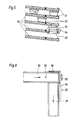
- Fig. 5 are substantially rectangular to that arranged in the region of one end of a storage aisle 30 multiple roller conveyor 20 can be raised and lowered Storage tracks 50 arranged, the roller conveyor 20 facing End in the high positions of the compartments 31 of the camp are located. These against those facing the roller conveyor 20 Can ends 50 sloping downward sloping be designed as roller conveyors, but it is also possible to train them as simple slides.
- the loading of the storage tracks 50 can by means of an in its inclination to the horizontal changeable conveyor belt (Not shown) or the like.
- stops 51 for the provided individual pieces to be stored. Furthermore, these are Stops 51 upstream about the width of the roller conveyor 20 extendable and retractable stop 52 upstream. By appropriate Control of the stopper 52 makes it possible to store the Pieces individually in between the respective stoppers 52 and the stop 51 lying area, or to let slip.
Description
Die Erfindung bezieht sich auf eine Einrichtung zum Verteilen von Stückgut gemäß dem Oberbegriff des unabhängigen Anspruches.The invention relates to a device for distribution of general cargo according to the generic term of the independent Claim.
Eine derartige Einrichtung wurde z.B. durch die US 5 239 349 A bekannt.Such a device has been e.g. by US 5 239 349 A known.
Bei dieser bekannten Einrichtung ist die Auflagerebene der Transportvorrichtung für die Stückgüter soweit angehoben, daß diese über der Auflagerebene der Ausschubeinrichtung liegt, wobei die Ausschubeinrichtung ständig aktiviert ist und sich über die gesamte Länge der Transportvorrichtung erstreckt.In this known device, the support level is the Transport device for the piece goods raised so far that this lies above the support level of the extension device, the extension device is constantly activated and itself extends over the entire length of the transport device.
Wird im bekannten Fall die Position eines bestimmten Faches erreicht, in das ein Stückgut eingeschoben werden soll, so wird die Transportvorrichtung soweit abgesenkt, bis sich deren Auflagerebene für die Stückgüter unterhalb der durch die obersten Mantellinien der Rollen der Ausschubeinrichtung bestimmten Ebene befinden, wodurch das Stückgut in das betreffende Fach eingeschoben wird.In the known case, the position of a certain subject reached into which a piece of goods is to be inserted, so the transport device is lowered until its Support level for the piece goods below the through the determined the top surface lines of the rollers of the extension device Level are located, whereby the general cargo in the concerned Tray is inserted.
Dadurch ergeben sich jedoch erhebliche Nachteile. So muß während des Transports der Stückgüter die Transportvorrichtung ständig angehoben werden, damit sich deren Auflagerebene für die Stückgüter über jener der Ausschubeinrichtung befindet.However, this has considerable disadvantages. So during the transport of the piece goods the transport device are constantly raised so that their support level for the general cargo is above that of the delivery device.
Da jede Rolle der Ausschubeinrichtung dieser bekannten Einrichtung über ein Zahnrad angetrieben wird, kann die Ausschubeinrichtung nur über die gesamte Länge der Transportvorrichtung wirksam werden. Somit ist es nicht möglich nur ein Warenstück von mehreren gleichzeitig auf der Transportvorrichtung befindlichen Warenstücken in eine Fach auszuschieben. Since each role of the ejector this known The device is driven by a gear wheel Extension device only over the entire length of the Transport device take effect. So it is not possible only one piece of several at the same time Transport device located goods in a compartment eject.
Ziel der Erfindung ist es, diese Nachteile zu vermeiden und eine Einrichtung der eingangs erwähnten Art vorzuschlagen, die sich durch einen einfachen Aufbau auszeichnet und ein rasches und gezieltes Einlagern von Waren auch bei einem geringen Abstand der einzulagernden Stückgüter auf der Transportvorrichtung ermöglicht.The aim of the invention is to avoid these disadvantages and propose a device of the type mentioned at the outset, which is characterized by a simple structure and a quick one and targeted storage of goods even with a small amount Distance of the piece goods to be stored on the Transport device allows.
Erfindungsgemäß wird dies bei einer Einrichtung der eingangs erwähnten Art durch die kennzeichnenden Merkmale des unabhängigen Anspruches erreicht.According to the invention, this is the case with a device of the beginning mentioned type by the characteristic features of the independent claim achieved.
Durch die vorgeschlagenen Maßnahmen ist es auf einfache Weise möglich einzelne auf der Transportvorrichtung befindliche Warenstücke in ein bestimmtes Fach eines Durchlaufregals einzuschieben. Dazu ist es lediglich erforderlich die dem betreffenden Fach zugeordnete Ausschubanordnung soweit anzuheben, daß die durch deren Riemen bestimmte Auflagerebene über jene der Transportvorrichtung liegt. Dabei ist es aber grundsätzlich auch möglich mehrere Fächer gleichzeitig durch entsprechendes Anheben der zugeordneten Ausschubanordnungen zu befüllen. Dabei ist es nicht unbedingt erforderlich die Transportvorrichtung anzuhalten.The proposed measures make it simple possible individual ones located on the transport device Pieces of goods in a specific compartment of a flow rack insert. All that is required is the Extension arrangement assigned to the relevant subject so far raise that the support level determined by their straps lies above that of the transport device. But it is in principle it is also possible to take several subjects at the same time appropriate lifting of the assigned extension arrangements fill. It is not absolutely necessary Stop the transport device.
Dadurch ist ein rasches Befüllen der einzelnen Fächer der Durchlaufregale möglich. Bei entsprechender Vorsortierung können die in einer bestimmten Etage angeordneten Fächer aufgefüllt werden und danach alle in einer nächsten Etage angeordneten Fächer.This enables the individual subjects to be filled quickly Flow racks possible. With appropriate pre-sorting can the compartments arranged on a certain floor be filled up and then all on a next floor arranged subjects.
Durch die Merkmale des Anspruches 2 ergibt sich eine in
konstruktiver Hinsicht sehr einfache Lösung. Dabei ist durch
die Verwendung eines dehnbaren Riemens der Vorteil einer
einfachen Halterung des Antriebsmotors gegeben, wobei in der
Arbeitsstellung des Trägers durch die erhöhte Spannung des
Antriebsriemens die Sicherheit der Mitnahme der Querrollen
erhöht wird und Schlupfprobleme vermieden werden.The features of
Ausgehend von einer Einrichtung gemäß dem Oberbegriff des
Anspruches 3 ist es vorteilhaft die kennzeichnenden Merkmale
des Anspruches 3 vorzusehen. Starting from a facility according to the preamble of
Die Erfindung wird nun anhand der Zeichnung näher erläutert. Dabei zeigen:
- Fig. 1
- schematisch einen Schnitt senkrecht zu einer Lagergasse eines Lagers mit einer erfindungsgemäßen Einrichtung,
- Fig. 2
- schematisch einen Schnitt parallel zu einer Lagergasse eines Lagers mit einer erfindungsgemäßen Einrichtung,
- Fig. 3
- einen Ausschnitt aus einer Rollenbahn mit einer Ausschubanordnung in axonometrischer Darstellung,
- Fig. 4
- einen Schnitt durch eine Ausschubanordnung,
- Fig. 5
- schematisch eine Einrichtung zur Beschickung einer erfindungsgemäßen Einrichtung,
- Fig. 6
- schematisch eine Draufsicht auf eine Übernahmeeinrichtung.
- Fig. 1
- schematically a section perpendicular to a warehouse aisle of a warehouse with a device according to the invention,
- Fig. 2
- schematically a section parallel to a warehouse aisle of a warehouse with a device according to the invention,
- Fig. 3
- a section of a roller conveyor with an extension arrangement in an axonometric view,
- Fig. 4
- a section through an extension arrangement,
- Fig. 5
- schematically a device for loading a device according to the invention,
- Fig. 6
- schematically a top view of a takeover device.
Bei einem Lager nach den Fig. 1 und 2 sind zu beiden Seiten
einer Lagergasse 30 Durchlaufregale 31 angeordnet, die
übereinanderliegende Fächer 32 zur Aufnahme von Stückgütern 23
aufweisen, wobei die Böden 33 der Fächer 32 von der Lagergasse
30 weg schräg geneigt abfallen.In a bearing according to FIGS. 1 and 2 are on both sides
a
In der Lagergasse 30 ist als Transporteinrichtung für die einzulagernden
Stückgüter 23 eine Rollenbahn 20 angeordnet, die
in ihren Endbereichen an Seilen 34 gehalten ist, die über
oberhalb der Durchlaufregale 31 gehaltene Umlenkrollen 38 zu
Seiltrommeln 35 geführt sind, die über eine gemeinsame
Welle 36 mit einem Antrieb 37 verbunden sind. Die vertikalen
Abschnitte der Seile 34 verlaufen dabei, wie aus der Fig. 2 zu
ersehen ist, im wesentlichen vor den Seitenwänden 39 der übereinanderliegenden
Fächer 32. Dadurch wird eine Behinderung des
Einschiebens der Stückgüter 23 in die einzelnen Fächer durch
die Seile 34 sicher verhindert. In
Um mit einer relativ geringen Leistung des Antriebes 37 das
Auslangen finden zu können, kann ein entsprechendes Gegengewicht
vorgesehen sein, das über ein entsprechendes Seil ebenfalls
an einer mit der gemeinsamen Welle 36 drehfest verbundenen
Seiltrommel festgelegt ist und gegenläufig zur Rollenbahn
1 gehoben und abgesenkt wird.To the with a relatively low power of the
Wie aus der Fig. 2 zu ersehen ist, sind an jeder Rollenbahn 20
im Bereich der übereinander angeordneten Fächer 32
Ausschubanordnungen 40 angeordnet, mit deren Hilfe aus einem
sich auf der betreffenden Rollenbahn 20 bewegenden Strom von
Stückgütern 23 ein einzelnes Stückgut 23 seitlich aus der
Rollenbahn 20 ausgeschoben und dabei in ein Fach 32
eingeschoben werden kann. Dabei ist es auch möglich die Stücke
von einer Rollenbahn 20 auf eine benachbarte Rollenbahn zu
übergeben. Dazu ist es lediglich erforderlich, die beiden
Rollenbahnen in eine gemeinsame Horizontalebene zu bringen,
was durch entsprechende Steuerung der Antriebe 37 ohne weiteres
erreichbar ist.As can be seen from FIG. 2, there are 20 on each roller conveyor
in the area of the
Die Beschickung der einzelnen Fächer der Durchlaufregale 31
erfolgt einfach in der Weise, daß die Stückgüter 23 auf die
Rollenbahn 20, in der zumindest einige der Rollen 2 (Fig. 3,
4) antreibbar sind, aufgegeben werden und bei Erreichung des
vorbestimmten Faches 32 mittels der Ausschubanordnung 40 in
dieses aus- bzw. einzuschieben. Ein Beispiel einer Einrichtung
zur Beschickung der Rollenbahn 20 ist in den Fig. 5 und 6 dargestellt.The loading of the individual compartments of the
Die Ausschubanordnungen 40 sind in den Fig. 3 und 4 näher
dargestellt.The
Eine Rollenbahn 20 (Fig. 3, 4) weist üblicherweise zwei Längsholme
1 auf, in denen in geringen Abständen Rollen 2 drehbar
gelagert sind, wobei die obersten Mantellinien der Rollen 2
über die Oberseiten 3 der Längsholme 1 noch oben vorragen.A roller conveyor 20 (FIGS. 3, 4) usually has two
An der Unterseite der Längsholme 1 ist ein Gehäuse 4 der Ausschubanordnung
40 befestigt, das an seinen in Richtung der
Längsholme verlaufenden Rändern mit nach außen gerichteten
Abwinkelungen 5 versehen ist. Diese sind von aus Gründen einer
besseren Übersichtlichkeit nicht dargestellten Schrauben
durchsetzt, die in die Längsholme 1 eingreifen.On the underside of the
Wie insbesondere aus der Fig. 4 zu ersehen ist, ist im Gehäuse
4 ein Antriebsmotor 6 ortsfest gehalten, der mit einer
Treibscheibe 7 versehen ist.As can be seen in particular from FIG. 4, is in the housing
4 a
Weiters ist am Boden 8 des Gehäuses 4 ein durch eine Zylinder-Kolben-Einheit
gebildete Hubeinrichtung 9 abgestützt, die
einen Träger 10 vertikal verstellbar hält.Furthermore, is at the
In diesem Träger 10, der parallel zu den Rollen 2 der Rollenbahn
20 verläuft, sind beim dargestellten Ausführungsbeispiel
drei Paare von Querrollen 11 drehbar gehalten. Jedes Paar von
Querrollen 11 ist von einem Paar von Schubriemen 12 umschlungen,
die nahe den Stirnseiten, bzw. Enden der Querrollen 11
angeordnet sind.In this
Der Antrieb der Querrollen 11 erfolgt über einen dehnbaren
Riemen 13 der über die Treibscheibe 7 des Motors 6, die näher
der in Längsrichtung verlaufenden Mitte der Rollenbahn 20 liegenden
Querrollen 11 der beiden äußeren Paare von Querrollen
11 und die beiden mittleren Querrollen 11 geführt ist. Dabei
verläuft der dehnbare Riemen 13 zwischen den paarweise angeordneten
Schubriemen 12.The
Zum Ausschieben eines in einem Strom von mit geringem gegenseitigen
Abstand auf der Rollenbahn 20 ankommenden Stückgutes
23 wird, sobald das Stückgut 23 in den Bereich der
Ausschubanordnung 40 gelangt ist, der Hubantrieb 9 aktiviert
und der Träger 10 angehoben, sodaß die obersten Mantellinien
der Schubriemen 12 oberhalb der obersten Mantellinien der Rollen
2 verlaufen. Gleichzeitig wird der in seiner Drehrichtung
umkehrbare Antriebsmotor 6 aktiviert und treibt über den dehnbaren
Riemen 13 die Schubriemen 12 in der gewünschten Richtung
an. Dadurch wird das nun auf den Schubriemen 12 liegende
Stückgut 23 quer zur Förderrichtung der Rollenbahn 20 aus
dieser ausgeschoben und in ein Fach 32 eines Durchgangsregales
31 eingeschoben.To push out one in a stream of little mutual
Distance on the
Wie aus der Fig. 5 zu ersehen ist, sind im wesentlichen rechtwinkelig
zu der im Bereich eines Endes einer Lagergasse 30 angeordneten
heb- und senkbaren Rollenbahn 20 angeordneten mehrere
Speicherbahnen 50 angeordnet, deren der Rollenbahn 20 zugekehrten
Enden sich in den Höhenlagen der Fächer 31 des Lagers
befinden. Diese gegen deren der Rollenbahn 20 zugekehrten
Enden schräg nach unten abfallenden Speicherbahnen 50 können
als Rollenbahnen ausgebildet sein, doch ist es auch möglich
diese als einfache Rutschen auszubilden.As can be seen from Fig. 5, are substantially rectangular
to that arranged in the region of one end of a
Die Beschickung der Speicherbahnen 50 kann mittels eines in seiner Neigung gegen die Horizontale veränderbares Förderband (nicht dargestellt) od. dgl. erfolgen.The loading of the storage tracks 50 can by means of an in its inclination to the horizontal changeable conveyor belt (Not shown) or the like.
An den Enden der Speicherbahnen 50 sind Anschläge 51 für die
einzelnen zu lagernden Stücke vorgesehen. Weiters sind diesen
Anschlägen 51 etwa um die Breite der Rollenbahn 20 vorgeordnete
aus- und einfahrbare Stopper 52 vorgeordnet. Durch entsprechende
Steuerung der Stopper 52 ist es möglich die zu lagernden
Stücke einzelweise in zwischen dem jeweiligen Stopper
52 und dem Anschlag 51 liegenden Bereich gleiten, bzw.
rutschen zu lassen.At the ends of the memory tracks 50 are
Wie aus der Fig. 6 zu ersehen ist, ist im Bereich des den
Speicherbahnen 50 zugekehrten Endes einer Rollenbahn 20 eine
Übernahmeeinrichtung 53 an dieser befestigt. Eine solche
Übernahmeeinrichtung 53 weist im wesentlichen eine Zylinder-Kolbenanordnung
54 auf, deren Kolbenstange 55 mit einem zu
dieser senkrecht abstehenden Schieber 56 verbunden ist.As can be seen from FIG. 6, the
Mit diesem Schieber 56 kann ein einzulagerndes Stück von einer
Speicherbahn 50 auf die heb- und senkbare Rollenbahn 20 geschoben
und über diese, wie oben beschrieben, in ein entsprechendes
Fach 32 des Lagers eingeschoben werden.With this
Claims (3)
- A device for distributing piece goods to a plurality of compartments of flow racks disposed in a storage aisle, in which there are provided a conveying apparatus for the conveyance of the piece goods to be distributed, which apparatus is held height-adjustable and conveys in the direction of the storage aisle, and a push-out device which conveys transversally to the storage aisle and comprises drivable transversal rollers (11) whose axes extend parallel to the conveying direction of the conveying apparatus, with the transversal rollers (11), or the plane determined by their uppermost surface lines respectively, being liftable by means of a lifting drive (9) above the bearing plane as determined by the uppermost surface lines of the elements of the conveying apparatus which carry the piece goods, characterized in that the conveying apparatus is formed in the known manner by a roller conveyor (20) whose uppermost surface lines project upwardly beyond the upper side of longitudinal crossbeams (1) and the push-out device comprises a number of push-out arrangements (40) corresponding to the number of the compartments disposed in a horizontal plane at one side of a storage aisle, which push-out arrangements are held individually and perpendicularly adjustable with lifting drives (9) with respect to the conveying apparatus and are formed by three pairs each of transversal rollers (11) rotatably held in a support (10), with one pair each of continuous push belts (12) being guided over two mutually adjacent transversal rollers (11) each and the transversal rollers (11) engage into intermediate spaces between two rollers each of the roller conveyor (20).
- A device as claimed in claim 1, characterized in that each push-out arrangement (40) is held in a housing (4) in which a drive (6, 7) of the transversal rollers (11) is arranged and an extensible push belt (13) is guided between the pairs of push belts (12) via at least one transversal roller (11) of each pair of transversal rollers (11).
- A device as claimed in one of the claims 1 or 2, in which in a storage aisle (30) there are provided in addition to the roller conveyor (20) at least one storage conveyor (50) as well as a transfer device (53) for pushing up the individual pieces onto the roller conveyor (20), characterized in that an arrangement of storage conveyors (50) are provided at the height levels of the compartments (32) of the storehouse, which storage conveyors are provided upstream of the roller conveyor (20), with the transfer device (53) being disposed at the end of the roller conveyor (20) facing the storage conveyors (50).
Applications Claiming Priority (3)
| Application Number | Priority Date | Filing Date | Title |
|---|---|---|---|
| AT635/95 | 1995-04-12 | ||
| AT63595A AT406151B (en) | 1995-04-12 | 1995-04-12 | DEVICE FOR DISTRIBUTING ITEMS |
| AT63595 | 1995-04-12 |
Publications (3)
| Publication Number | Publication Date |
|---|---|
| EP0737631A2 EP0737631A2 (en) | 1996-10-16 |
| EP0737631A3 EP0737631A3 (en) | 1996-12-11 |
| EP0737631B1 true EP0737631B1 (en) | 2002-07-24 |
Family
ID=3495811
Family Applications (1)
| Application Number | Title | Priority Date | Filing Date |
|---|---|---|---|
| EP19960890061 Expired - Lifetime EP0737631B1 (en) | 1995-04-12 | 1996-03-29 | Distribution device for articles |
Country Status (7)
| Country | Link |
|---|---|
| EP (1) | EP0737631B1 (en) |
| JP (1) | JPH0977215A (en) |
| AR (1) | AR001442A1 (en) |
| AT (1) | AT406151B (en) |
| BR (1) | BR9601327A (en) |
| DE (1) | DE59609464D1 (en) |
| ES (1) | ES2180727T3 (en) |
Families Citing this family (10)
| Publication number | Priority date | Publication date | Assignee | Title |
|---|---|---|---|---|
| DE19823083A1 (en) * | 1998-05-22 | 1999-11-25 | Dynamic Systems Engineering B | Dispatch holding unit for food wholesale warehouse has a series of |
| DE20206257U1 (en) * | 2002-04-19 | 2002-07-04 | Otto Versand Gmbh & Co | Device for sorting, storing and sorting out goods |
| ITBO20100267A1 (en) * | 2010-04-29 | 2011-10-30 | Resta Srl | SYSTEM OF HANDLING AND STORAGE OF PLANAR PANELS SUBSTANTIALLY SOFT AND FLEXIBLE, PARTICULARLY FOR MATTRESSES AND THE LIKE. |
| US9919870B2 (en) | 2011-07-01 | 2018-03-20 | Effimat Storage Technology Aps | Vertical lift storage system and a method of operating a lift |
| AT511793A1 (en) * | 2011-08-11 | 2013-02-15 | Tgw Logistics Group Gmbh | LIFTING RACK AND THEREFORE EQUIPPED STORAGE SYSTEM |
| NL2015045B1 (en) * | 2015-06-29 | 2017-01-24 | Stichting Sangria | Elevator and system for transporting and storing objects. |
| NO20160118A1 (en) | 2016-01-26 | 2017-07-27 | Autostore Tech As | Remotely operated vehicle |
| SE542560C2 (en) * | 2017-12-08 | 2020-06-02 | Weland Lagersystem Ab | A vertical storage lift and a storage and retrieval system comprising such |
| DE102020122391A1 (en) * | 2020-08-27 | 2022-03-03 | Rocket Solution Gmbh | Elevator and shelving system |
| CN113548359A (en) * | 2021-08-17 | 2021-10-26 | 中汽昌兴(洛阳)机电设备工程有限公司 | Stereoscopic warehouse |
Family Cites Families (6)
| Publication number | Priority date | Publication date | Assignee | Title |
|---|---|---|---|---|
| US3492704A (en) * | 1967-06-15 | 1970-02-03 | Donald D Schwellenbach | Apparatus for making concrete blocks |
| ES451578A1 (en) * | 1976-09-16 | 1977-12-01 | Movimiento Ind Y Manutencion S | Automatic procedure to provide and distribute various elements to pre-established places. (Machine-translation by Google Translate, not legally binding) |
| JPS5912005A (en) * | 1982-07-09 | 1984-01-21 | Kao Corp | Case supply machine |
| DE3779966T2 (en) * | 1986-07-24 | 1992-12-10 | Kao Corp | METHOD FOR ASSEMBLING GOODS. |
| DE3639649A1 (en) * | 1986-11-20 | 1988-05-26 | Tepora Transportsysteme Entwic | STORAGE FACILITIES |
| US5238349A (en) * | 1992-03-10 | 1993-08-24 | Grace Sr Robert W | Article sorting and retrieval system |
-
1995
- 1995-04-12 AT AT63595A patent/AT406151B/en not_active IP Right Cessation
-
1996
- 1996-03-27 AR AR33293196A patent/AR001442A1/en unknown
- 1996-03-29 EP EP19960890061 patent/EP0737631B1/en not_active Expired - Lifetime
- 1996-03-29 ES ES96890061T patent/ES2180727T3/en not_active Expired - Lifetime
- 1996-03-29 DE DE59609464T patent/DE59609464D1/en not_active Expired - Fee Related
- 1996-04-08 JP JP8557796A patent/JPH0977215A/en active Pending
- 1996-04-11 BR BR9601327A patent/BR9601327A/en not_active IP Right Cessation
Also Published As
| Publication number | Publication date |
|---|---|
| BR9601327A (en) | 1998-01-13 |
| ATA63595A (en) | 1999-07-15 |
| EP0737631A3 (en) | 1996-12-11 |
| EP0737631A2 (en) | 1996-10-16 |
| ES2180727T3 (en) | 2003-02-16 |
| AR001442A1 (en) | 1997-10-22 |
| DE59609464D1 (en) | 2002-08-29 |
| AT406151B (en) | 2000-03-27 |
| JPH0977215A (en) | 1997-03-25 |
Similar Documents
| Publication | Publication Date | Title |
|---|---|---|
| EP0744362B1 (en) | Device for a roller-conveyor | |
| AT500551B1 (en) | LOAD RACK FRAME FOR A SHELVING UNIT | |
| WO2002076859A1 (en) | Storage lift | |
| EP0737631B1 (en) | Distribution device for articles | |
| DE4400829B4 (en) | Storage and retrieval unit | |
| EP0286986A1 (en) | Storage device | |
| DE3915074A1 (en) | C-CONVEYOR | |
| DE3336988C2 (en) | Device for feeding in large numbers of objects | |
| AT398302B (en) | DEVICE FOR STORING TABLE OR PLATE-SHAPED OBJECTS | |
| EP1144282B1 (en) | Picking store for piece goods | |
| DE2233832B2 (en) | Device for conveying objects | |
| EP2551217A1 (en) | Conveyor device for articles | |
| WO2005097631A1 (en) | Shelf warehouse and vertical transport device | |
| DE10044048B4 (en) | Device for transferring means of transport | |
| EP0683118B1 (en) | Storage device for article especially storage containers | |
| DE19637949B4 (en) | Device for loading and unloading a floor surface with transport objects | |
| DE8535683U1 (en) | Conveyor device with driven, reinforced belts for transporting loaded pallets | |
| EP1831096B1 (en) | Method and device for manipulating at least one unit load | |
| DE4025368A1 (en) | Stacking magazine for both crates - has lift chain with transport elements on only one side of transporter | |
| DE2656303A1 (en) | Roller track for rod shaped material - has rollers alternatively inclined in opposite direction between two side members | |
| DE3431580A1 (en) | Conveying device for a wide variety of articles, with or without pallets | |
| DE4423545A1 (en) | Storage and retrieval unit | |
| DE2421515C3 (en) | Turning and storage device for cheese or the like | |
| AT230800B (en) | Arrangement for the transport of container units | |
| DE1244657B (en) | Live rack with horizontal conveyance of goods supported by carriers, in particular goods hung on them |
Legal Events
| Date | Code | Title | Description |
|---|---|---|---|
| PUAI | Public reference made under article 153(3) epc to a published international application that has entered the european phase |
Free format text: ORIGINAL CODE: 0009012 |
|
| AK | Designated contracting states |
Kind code of ref document: A2 Designated state(s): DE ES FR GB IT |
|
| PUAL | Search report despatched |
Free format text: ORIGINAL CODE: 0009013 |
|
| AK | Designated contracting states |
Kind code of ref document: A3 Designated state(s): DE ES FR GB IT |
|
| 17P | Request for examination filed |
Effective date: 19970224 |
|
| 17Q | First examination report despatched |
Effective date: 19990727 |
|
| GRAG | Despatch of communication of intention to grant |
Free format text: ORIGINAL CODE: EPIDOS AGRA |
|
| GRAG | Despatch of communication of intention to grant |
Free format text: ORIGINAL CODE: EPIDOS AGRA |
|
| GRAH | Despatch of communication of intention to grant a patent |
Free format text: ORIGINAL CODE: EPIDOS IGRA |
|
| GRAH | Despatch of communication of intention to grant a patent |
Free format text: ORIGINAL CODE: EPIDOS IGRA |
|
| GRAA | (expected) grant |
Free format text: ORIGINAL CODE: 0009210 |
|
| AK | Designated contracting states |
Kind code of ref document: B1 Designated state(s): DE ES FR GB IT |
|
| REG | Reference to a national code |
Ref country code: GB Ref legal event code: FG4D Free format text: NOT ENGLISH |
|
| REF | Corresponds to: |
Ref document number: 59609464 Country of ref document: DE Date of ref document: 20020829 |
|
| RAP2 | Party data changed (patent owner data changed or rights of a patent transferred) |
Owner name: SSI SCHAEFER FOERDERTECHNIK GMBH |
|
| GBT | Gb: translation of ep patent filed (gb section 77(6)(a)/1977) |
Effective date: 20021004 |
|
| RAP2 | Party data changed (patent owner data changed or rights of a patent transferred) |
Owner name: SSI SCHAEFER PEEM GMBH |
|
| ET | Fr: translation filed | ||
| REG | Reference to a national code |
Ref country code: ES Ref legal event code: FG2A Ref document number: 2180727 Country of ref document: ES Kind code of ref document: T3 |
|
| PLBE | No opposition filed within time limit |
Free format text: ORIGINAL CODE: 0009261 |
|
| STAA | Information on the status of an ep patent application or granted ep patent |
Free format text: STATUS: NO OPPOSITION FILED WITHIN TIME LIMIT |
|
| 26N | No opposition filed |
Effective date: 20030425 |
|
| PGFP | Annual fee paid to national office [announced via postgrant information from national office to epo] |
Ref country code: ES Payment date: 20050217 Year of fee payment: 10 |
|
| PGFP | Annual fee paid to national office [announced via postgrant information from national office to epo] |
Ref country code: FR Payment date: 20050314 Year of fee payment: 10 |
|
| PGFP | Annual fee paid to national office [announced via postgrant information from national office to epo] |
Ref country code: GB Payment date: 20050323 Year of fee payment: 10 |
|
| PGFP | Annual fee paid to national office [announced via postgrant information from national office to epo] |
Ref country code: DE Payment date: 20050429 Year of fee payment: 10 |
|
| PG25 | Lapsed in a contracting state [announced via postgrant information from national office to epo] |
Ref country code: GB Free format text: LAPSE BECAUSE OF NON-PAYMENT OF DUE FEES Effective date: 20060329 |
|
| PG25 | Lapsed in a contracting state [announced via postgrant information from national office to epo] |
Ref country code: ES Free format text: LAPSE BECAUSE OF NON-PAYMENT OF DUE FEES Effective date: 20060330 |
|
| PGFP | Annual fee paid to national office [announced via postgrant information from national office to epo] |
Ref country code: IT Payment date: 20060331 Year of fee payment: 11 |
|
| PG25 | Lapsed in a contracting state [announced via postgrant information from national office to epo] |
Ref country code: DE Free format text: LAPSE BECAUSE OF NON-PAYMENT OF DUE FEES Effective date: 20061003 |
|
| GBPC | Gb: european patent ceased through non-payment of renewal fee |
Effective date: 20060329 |
|
| REG | Reference to a national code |
Ref country code: FR Ref legal event code: ST Effective date: 20061130 |
|
| REG | Reference to a national code |
Ref country code: ES Ref legal event code: FD2A Effective date: 20060330 |
|
| PG25 | Lapsed in a contracting state [announced via postgrant information from national office to epo] |
Ref country code: FR Free format text: LAPSE BECAUSE OF NON-PAYMENT OF DUE FEES Effective date: 20060331 |
|
| PG25 | Lapsed in a contracting state [announced via postgrant information from national office to epo] |
Ref country code: IT Free format text: LAPSE BECAUSE OF NON-PAYMENT OF DUE FEES Effective date: 20070329 |