EP0736748A2 - Verfahren und Vorrichtung zum Ausrichten von Rohren mittels Laser - Google Patents
Verfahren und Vorrichtung zum Ausrichten von Rohren mittels Laser Download PDFInfo
- Publication number
- EP0736748A2 EP0736748A2 EP96302372A EP96302372A EP0736748A2 EP 0736748 A2 EP0736748 A2 EP 0736748A2 EP 96302372 A EP96302372 A EP 96302372A EP 96302372 A EP96302372 A EP 96302372A EP 0736748 A2 EP0736748 A2 EP 0736748A2
- Authority
- EP
- European Patent Office
- Prior art keywords
- target
- light
- aligning
- control
- pipeline
- Prior art date
- Legal status (The legal status is an assumption and is not a legal conclusion. Google has not performed a legal analysis and makes no representation as to the accuracy of the status listed.)
- Withdrawn
Links
Images


Classifications
-
- G—PHYSICS
- G01—MEASURING; TESTING
- G01B—MEASURING LENGTH, THICKNESS OR SIMILAR LINEAR DIMENSIONS; MEASURING ANGLES; MEASURING AREAS; MEASURING IRREGULARITIES OF SURFACES OR CONTOURS
- G01B11/00—Measuring arrangements characterised by the use of optical techniques
- G01B11/26—Measuring arrangements characterised by the use of optical techniques for measuring angles or tapers; for testing the alignment of axes
- G01B11/27—Measuring arrangements characterised by the use of optical techniques for measuring angles or tapers; for testing the alignment of axes for testing the alignment of axes
-
- G—PHYSICS
- G01—MEASURING; TESTING
- G01C—MEASURING DISTANCES, LEVELS OR BEARINGS; SURVEYING; NAVIGATION; GYROSCOPIC INSTRUMENTS; PHOTOGRAMMETRY OR VIDEOGRAMMETRY
- G01C15/00—Surveying instruments or accessories not provided for in groups G01C1/00 - G01C13/00
- G01C15/002—Active optical surveying means
Definitions
- This invention relates generally to alignment instruments used in construction and, in particular, to an apparatus for aligning individual sections of pipe in a pipeline. More particularly the invention relates to a self-aligning laser beam method and apparatus for laying pipe such as sewer pipe, and to a self-aligning sewer pipe laser.
- an active target which is equipped with a plurality of photocells arranged in a particular pattern to automatically align the laser beam.
- the active target includes a controller which responds to a laser beam striking the photocells in order to transmit a control signal to a controller in the laser.
- the laser responds to the control signal by repositioning the beam. While such device eliminates the requirement for two workers, it introduces additional cost and complexity in the apparatus.
- the active target requires electronic circuitry and must be powered from a separate battery.
- the present invention aims to alleviate the problems of the prior art.
- Another aspect of the invention provides a method of aligning individual sections of pipe in a pipeline, including: positioning a laser unit at one end of a laid section of a pipeline and positioning a target at an opposite end of said pipeline, wherein said target has a retroreflective portion facing said laser unit; directing a beam of collimated light from said laser unit in the general direction of said target and moving said beam in a first lateral direction; looking for a reflection of said beam from said retroreflective portion while monitoring the position of said beam; if a reflection of said beam is found during said looking, positioning said beam at the centre of the reflection, and providing an indication that the target has been found; and if a reflection of said beam is not found during said looking, positioning said beam at a predetermined location, and providing an indication that the target has not been found.
- said directing a beam includes moving said beam in a second opposite lateral direction after moving said beam in the first lateral direction.
- said directing a beam includes moving said beam in said first and second directions including moving said beam in an arc of approximately 17 degrees.
- said retroreflective portion includes a pair of spaced apart retroreflective strips and wherein said looking includes looking for a reflection of said beam from each of said strips.
- said positioning said beam at the centre of the reflection includes positioning said beam at the centre between said reflections from said strips.
- the method includes modulating said beam of light.
- said directing a beam includes directing said beam outside of said pipeline and said positioning includes positioning said target outside said pipeline.
- said laser unit and said target are positioned above said pipeline.
- said directing a beam may include directing said beam within said pipeline and said positioning includes positioning said target within said pipeline.
- said directing a beam includes measuring an angular width of one of said retroreflective strips, moving said beam in a second opposite lateral direction as a function of said angular width in order to position said beam outside of said pair of retroreflective strips, and redirecting said beam in said first lateral direction.
- a method and apparatus for aligning individual sections of pipe include directing a beam of collimated light in the general direction of a pipeline and scanning the beam laterally.
- a target, having a retro reflective portion may be positioned in a location that will be traversed by the scanning beam.
- a reflection of the beam produced by the reflective portion may be received and processed.
- the scanning may be discontinued when the reflective portion is located and the beam is aimed in a direction related to the position of the retro reflective target.
- a pipe-aligning apparatus and method of aligning individual sections of pipe in a pipeline are provided, eliminating the requirement for two workers in order to re-establish the equipment and extend a previously laid portion of pipeline. This objective may be met with the use of a passive target which does not require complicated electronic circuitry and batteries.
- Preferred constructions provide an improved method for laying pipe in a curved section.
- a method of aligning individual sections of pipe includes directing a beam of collimated light generally in the general direction of a pipeline and scanning the beam laterally.
- a target having a retroreflective portion, may be positioned in a location that will be traversed by the scanning beam.
- a reflection of the beam produced by the reflective portion may be received and processed.
- the scanning may be discontinued when the reflective portion is located and the beam is aimed in a direction related to the position of the retroreflective target.
- a pipe-aligning apparatus including a laser unit and a target.
- the laser unit may include a source for generating a collimated beam of light and a scanning device for scanning the beam of collimated light laterally.
- the laser unit may further include a receiver for receiving light and a control that is responsive to the receiver and to the scanning device in order to provide an indication of the position of the beam when the receiver receives light.
- the control preferably causes the scanning device to position the beam as a function of the indication.
- the target preferably has a retroreflective portion to reflect the beam to the receiver.
- the control preferably positions the beam with respect to the retroreflective portion provided that the target is positioned in the scanning beam.
- the apparatus may further include a remote control unit including a user input selection device, a signal generator, and a remote control circuit which preferably controls the signal generator in response to user activation of the user input selection device to produce a signal that is received by the laser unit receiver in order to provide commands to the laser unit control.
- the mode of the laser unit may be adjusted remotely from the location of the target in order to improve the functionality of the unit.
- the signal output from the remote control unit is light which may be in the same band or in a different band as that generated by the laser unit, but distinguishable from the laser unit's light.
- a preferred embodiment of apparatus in accordance with the invention may be utilized to lay straight sections of pipe by scanning a beam within the pipeline and positioning the target within the pipeline.
- target preferably includes a pair of retroreflective strips, which are positioned on opposite sides of a visual beam indicator. In this manner, the retroreflective strips do not interfere with the normal operation of aligning additional sections of pipe using the beam indicator.
- the beam is preferably laterally aligned to previously laid sections of pipe utilizing such target by determining the position of the beam when reflected from each of the retroreflective strips and repositioning the beam midway between the two positions.
- the beam is preferably scanned outside of the pipeline such as in a position above the pipeline.
- the target may then be positioned at the distal end of each new section of pipe and utilized to redirect the beam laterally in the direction of the curved pipe.
- the beam may be easily realigned as each new section of curved pipe is added to establish grade at the distal end of each section of pipe.
- the lateral position of each curved section of pipe may be established by conventional techniques, such as by surveying.
- the grade of the pipes may be established utilizing the grade-aligning feature of the laser unit.
- scanning light beam and the remote control light output are preferably in the visible spectrum, one or both of these may have a non-visible frequency in some embodiments.
- the invention also envisages and extends to any combination of the features of the above aspects or their optional or preferred features which is not specifically set out herein.
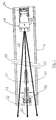
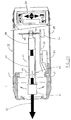
- Pipe-aligning apparatus 15 includes a laser unit 18 and a target 20.
- Laser unit 18 generates a collimated beam of light 22 in either infrared or visible wavelengths, which scans laterally across the face of target 20.
- Light beam 22 is reflected toward laser unit 18 by a retroreflective portion of target 20, as illustrated by reflected beam 24.
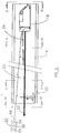
- Laser unit 18 includes a housing 25 having a first end 26 thereof. End 26 includes a light source generally indicated at 28 for generating light beam 22 and a receiver 30 for receiving reflected beam 24. Receiver 30 includes a photosensor 31 and a light-collecting surface 33 surrounding the sensor. Housing 25 includes a second end 32 upon which is positioned a control panel 34.
- Control panel 34 includes a display 36 for reading out the grade angle at which laser unit 18 is set and at least a general indication of the lateral angle of beam 22. Display 36 may additionally include indicia which advise the operator of the mode of operation of the laser unit as well as various operation conditions of the laser unit.
- Control panel 34 further includes user input switches 38 which receive user input selections to raise or lower the grade level and manually direct the beam laterally left or right and selection switches 40 which allow the operator to select the mode of operation of the laser unit.
- Target 20 includes a face 42, which is directed away from laser unit 18 (Fig. 6), and an opposite face 44, which is directed in the direction of laser unit 18 (Fig. 5).
- Target 20 includes a pair of feet 46, which rest upon the inner-curved surface of pipeline 16.
- the target includes a beam alignment indicator 48 which is made of a sheet of translucent material in order to view the location of beam 22 upon the indicator.
- the indicator may include a central bull's-eye 50, which visually indicates that the beam 22 is centrally positioned within pipeline 16.
- Face 44 of target 20 has a retroreflective portion made up of a pair of retroreflective strips 52, which are spaced apart and positioned on opposite sides of beam alignment indicator 48. Bull's-eye 50 is located centrally between retroreflective strips 52.
- Laser unit 18 scans beam 22 with the structure revealed in more detail in Fig. 11.
- a frame member 41 is pivotally mounted at 43 to a second frame member 45.
- Frame member 45 is pivotally mounted at 47 to the housing.
- a line motor 74 laterally pivots frame member 41 about pivot 43 by a threaded shaft 49 and nut 51.
- Light source 28 and photosensor 31 are mounted to opposite ends of frame member 41.
- a grade motor 53 engages an extension 55 of second frame member 45 in order to pivot the second frame member about pivot 47. This motion of second frame member 45 under the control of grade motor 53 adjusts the elevation (grade) of source 28.
- grade motor 53 is a DC servo motor.
- line motor 74 is a stepper motor.
- light source 28 is a laser-diode unit of the type which is readily available from numerous commercial suppliers but could be a gas laser or other source of visible or invisible light.
- a beam focusing and alignment member 57 processes the radiation produced by light source 28 into a collimated beam.
- Another motor (not shown), which is a stepper motor in the illustrated embodiment, adjusts the angle of an inclinometer (not shown) relative to frame member 41 in order to provide adjustment of the elevation, or grade, of beam 22.
- the operator enters the desired beam elevation (grade) into the laser unit utilizing switches 38 and waits for the unit to internally level and elevate the beam to the correct grade according to conventional techniques.
- the operator then places the laser unit in a scanning mode which will cause the laser unit to modulate the light beam 22 and sweep the beam radially within the inclined plane determined by the beam elevation, as illustrated in Fig. 1.
- the laser unit concurrently monitors receiver 30 for indication of a detected return reflection beam 24 produced by beam 22 sweeping across retroreflective strips 52.
- the position of the beam 22 when a reflected beam is received is retained and processed in order to determine a centre between the two reflective strips which should correspond with bull's-eye 50.
- Laser unit 18 will then align beam 22 to bull's-eye 50 and discontinue modulation of the laser beam.
- the modulation of the laser beam is, in the illustrative embodiment, a simple duty cycle modulation, which allows the laser unit to discriminate reflected beam 24 from other light sources, including ambient light. If the target has been successfully located, the laser unit indicates that fact by illuminating an appropriate indicia on display panel 36 and, thereafter, reverts to normal operation. If the return reflection from the target is not detected after a given interval, the laser unit indicates that fact with an indicia on display panel 36, discontinues modulating and sweeping the beam, and pauses for input from the user.
- An optional remote control unit 54 includes a plurality of user input selection buttons 56 and a source which generates a signal 58, which is a light beam which may be in the same or in a different wavelength band as beam 22 and is received by receiver 30.
- remote control 54 allows the user to manually adjust the lateral positioning of beam 22 within the inclined plane (grade) and allows the user to turn the beam on and off remotely.
- the user can erect laser unit 18 before placing the target 20 in position.
- Remote control 54 will also be useful when repetitively aligning the beam to different line positions as in the case of laying curved pipeline via over-the-top operation as illustrated in Fig. 10 and as described in more detail below.
- remote control 54 To use remote control 54, the user would first erect the laser unit and then enter the desired beam elevation (grade) into the laser unit utilizing switches 38 and actuate appropriate switches to enable initiation of search cycle via remote control. The user would then place target 20 in the end of the pipe. The user would then press the appropriate buttons on the remote control to begin a search cycle. Once activated, the laser unit will modulate the laser beam, sweep it radially within the inclined plane determined by the beam elevation, and monitor the received beam, in the manner previously described, until a reflected beam establishes a location of a target, at which time the beam is positioned relative to the target.
- the user may either actuate the appropriate buttons on remote control 54 to initiate another search cycle or, alternatively, may press a beam ON/OFF button on the remote control to turn off remote control of the self-aligning feature and thus allow manual positioning of the beam using the remote control.
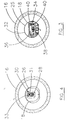
- Laser unit 18 includes a control, generally indicated at 60, having a first microprocessor 62 and a second microprocessor 64.
- the output of receiver photocell 30 is amplified utilizing a preamplifier stage 66 and an amplifier stage 68 and supplied to a comparator stage 70 where it is determined when the level of light detected by a photocell 30 exceeds a predetermined threshold.
- An output 71 of comparator stage 70 is provided as an input to processor 62, which also interfaces with control panel 34.
- Processor 64 communicates with processor 62 over a bus 70.
- Processor 64 controls the operation of source laser 28 and a circuit 72 which operates a line motor 74 in order to sweep the laser laterally, as illustrated in Fig. 1.
- line motor 74 is a stepper motor which moves in increments in response to a command from processor 64.
- processor 64 has information at all times of the position of line motor 74. It should be apparent to one of ordinary skill in the art that other techniques could be utilized for monitoring the position of the line motor, and, hence, the generated beam 22, such as by feedback encoders and the like.
- source laser 28 generates a modulated laser beam 22 which is reflected from target 20 as reflected beam 24 which is received by receiver photocell 30.
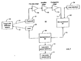
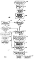
- a control program 76 for processor 62 is illustrated in Fig. 8.
- Program 76 responds at 78 to the user activating the automatic alignment switch by sending commands at 80 to processor 64 in order to initiate the automatic alignment, or line seek, mode. If it is determined at 90 that processor 64 has provided an indication that it has stopped searching because no target is found, an indication is provided (92) on display panel 36 and the control goes into a quiescent state (93) awaiting further commands. If it is determined (94) that processor 64 has provided an indication that a target has been found, an indication is provided (96) on display panel 36 and the control returns to a normal mode (98), provided that the control is in a standard mode of operation.
- processor 62 monitors (82) photocell 30 in order to detect the modulated beam 24. A check is made at 84 as to whether the detected light is of the correct modulation frequency. If it is, processor 62 sends (86) a command over bus 70 to indicate that processor 62 detected the leading edge of a reflected beam 24. A second command is issued at 88 when processor 62 detects the trailing edge of reflected beam 24. If it is determined at 84 that the received light is not of the correct frequency, then program 76 again looks for indications from processor 64 (90, 94).
- Program 76 responds at 78 to the user activating an alternate mode by monitoring (79) photocell 30 in order to detect signals from remote control 54. If a signal is detected, it is determined (81) whether a sleep command is received or a right/left sweep command is received. If a sleep command is received, the control returns to normal, standard mode (83). If a right/left sweep command is received, the line seek mode is invoked (80) and the control looks for indications from processor 64 (90, 94). If a "target found" indication is received (94, 96), the control returns to 79 to look for additional commands from the remote control. Otherwise, the control operates in the same manner as in the standard mode of operation.
- Control program 100 for processor 64 is illustrated in Fig. 9.
- Control program 100 is initiated at 102 when a "enter line seek" signal is received from processor 62 indicating that the automatic alignment function is requested.
- Processor 64 then modulates (104) the beam generated by laser 28 and initiates movement (106) of the stepper motor 74.
- Processor 64 then waits (108) for a signal over bus 70 from processor 62 indicating receipt of a valid reflected beam 24. It is then determined (110) whether such reflected beam is detected before the line has moved fully to the end of travel in one direction. If the reflection is detected, then the width of the strip, in angular units is measured (112). The width of the strip is measured from the trailing edges of the reflection and includes the width of the beam.
- the beam direction is momentarily reversed in order to find another trailing edge and thereby ensure that the entire strip width has been scanned.
- the line motor 74 is then moved in the direction opposite the direction of the initial search by a constant member related to the measured strip width that will ensure that both strips will be traversed in the subsequent scan.
- the constant member takes into account the known ratio of actual strip width to strip separation distance and, in the illustrated embodiment, is at least three times the strip width measured at 112. This should bring the beam to the opposite side of both reflective strips 52.
- the direction of the line motor is again reversed (116) and moved more slowly while looking for indications from processor 62 of received reflections. If two reflections are received (118), the measurement is successful and processor 64 moves (119) line motor 74 to the measured centre of the strips, demodulates 120 the beam, and provides an indication (121) to processor 62 that the target has been successfully located.
- line motor 74 moves the line in the opposition direction. If a reflection is detected (123), an attempt is made to locate the two strips and centre the line motor (112-121). If no reflection is detected (123) even though the line motor has reversed, it is concluded that the target is not present. The line motor is moved to some arbitrary position (124), the beam is demodulated (126) and an indication is provided (128) to processor 62 that no target is found. If routine 100 is not able to obtain a successful measurement of the width of a strip (112) or if only one of two reflective strips is located (118), then the self-aligning function is aborted (124-128) .
- the self-aligning function (76, 100) addresses the difficulties associated with accurately locating the two strips 52 of retroreflective tape at both close-in distances and far-away distances. This is accomplished by first determining an angular width of a strip and then beginning a new scan after backing up the line a sufficient angular amount to scan over both of the strips.
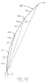
- FIG. 10 A method of utilizing pipe-aligning apparatus 15 to lay a curved section of pipe is illustrated in Fig. 10, wherein a section of curved pipe 140, which is made up of a plurality of individual sections 142 is laid utilizing pipe-aligning apparatus 15'.
- the laser unit of apparatus 15' is positioned on top of pipe section 140.
- the user positions the target at a first interface 144 between pipe sections 142 and aligns beam 22' on the target.
- a new section 142 is then put into place using conventional techniques, such as surveying procedures, to laterally position the distal end of the new section.
- the target is moved to interface 144 with the new section 142 and the reflected beam 22' is realigned with the target.
- the present invention comprehends the use of pipe-aligning apparatus 15' to also locate the lateral position of the distal end of each new section 142 by reading the angular position of the beam and matching such reading with corresponding data on the pipeline layout drawing.
- laser unit 18 sweeps laser beam 22 along a path of 15 feet on each side of centreline at a 100-foot distance. This is equal to approximately 8.5 degrees from each side of centreline or approximately a 17-degree total sweep.
- preferred constructions provide a pipe-laying method and apparatus that is both easy to use and increases the capabilities of the operator in laying pipe.
- the operator is provided with the capability of single-handed operation of the apparatus from either the position of the laser unit or the position of the target.
- preferred constructions are capable of use in laying curved sections of pipe as well as straight sections.
Landscapes
- Physics & Mathematics (AREA)
- General Physics & Mathematics (AREA)
- Engineering & Computer Science (AREA)
- Radar, Positioning & Navigation (AREA)
- Remote Sensing (AREA)
- Length Measuring Devices By Optical Means (AREA)
Applications Claiming Priority (2)
| Application Number | Priority Date | Filing Date | Title |
|---|---|---|---|
| US415663 | 1982-09-07 | ||
| US08/415,663 US5621531A (en) | 1995-04-03 | 1995-04-03 | Self-aligning sewer pipe laser |
Publications (2)
| Publication Number | Publication Date |
|---|---|
| EP0736748A2 true EP0736748A2 (de) | 1996-10-09 |
| EP0736748A3 EP0736748A3 (de) | 1997-12-10 |
Family
ID=23646655
Family Applications (1)
| Application Number | Title | Priority Date | Filing Date |
|---|---|---|---|
| EP96302372A Withdrawn EP0736748A3 (de) | 1995-04-03 | 1996-04-03 | Verfahren und Vorrichtung zum Ausrichten von Rohren mittels Laser |
Country Status (3)
| Country | Link |
|---|---|
| US (1) | US5621531A (de) |
| EP (1) | EP0736748A3 (de) |
| JP (1) | JPH08338722A (de) |
Cited By (4)
| Publication number | Priority date | Publication date | Assignee | Title |
|---|---|---|---|---|
| WO2001086078A1 (en) * | 2000-05-05 | 2001-11-15 | Laser Alignment, Inc., A Leica Geosystems Company | Laser-guided construction equipment |
| FR2857739A1 (fr) * | 2003-07-18 | 2005-01-21 | Barassi Fils | Procede et systeme d'alignement de tuyau utilisant un laser |
| GB2540194A (en) * | 2015-07-09 | 2017-01-11 | Skf Ab | System and method for laser alignment of rotary components |
| CN111590230A (zh) * | 2019-02-20 | 2020-08-28 | 中建五洲工程装备有限公司 | 一种透光装置及使用方法 |
Families Citing this family (20)
| Publication number | Priority date | Publication date | Assignee | Title |
|---|---|---|---|---|
| US6124935A (en) * | 1995-04-05 | 2000-09-26 | Matthews; David S. | Pipe fitting alignment systems |
| US6262801B1 (en) | 1995-05-25 | 2001-07-17 | Kabushiki Kaisha Topcon | Laser reference level setting device |
| CN1143120C (zh) * | 1995-05-25 | 2004-03-24 | 株式会社拓普康 | 激光基准水平面设定装置 |
| JP3837609B2 (ja) * | 1996-03-19 | 2006-10-25 | 株式会社トプコン | レーザー照射装置 |
| AU2217999A (en) * | 1998-01-08 | 1999-07-26 | Paul Akers | Laser levelling system, apparatus and method for building construction |
| US6108076A (en) * | 1998-12-21 | 2000-08-22 | Trimble Navigation Limited | Method and apparatus for accurately positioning a tool on a mobile machine using on-board laser and positioning system |
| US6308428B1 (en) | 1998-12-22 | 2001-10-30 | Pinpoint Laser Systems | Laser alignment system |
| JP2000241163A (ja) * | 1999-01-01 | 2000-09-08 | Kiyotaka Ito | 土木工事用分離型レーザ測定器 |
| US6253160B1 (en) | 1999-01-15 | 2001-06-26 | Trimble Navigation Ltd. | Method and apparatus for calibrating a tool positioning mechanism on a mobile machine |
| US6622392B1 (en) | 1999-03-19 | 2003-09-23 | Laser Alignment, Inc. | Target with diffractive elements for use with laser beam generating devices |
| US6470251B1 (en) | 2000-08-31 | 2002-10-22 | Trimble Navigation Limited | Light detector for multi-axis position control |
| US6588808B1 (en) | 2002-02-22 | 2003-07-08 | General Electric Company | Locomotive rail conditioning system alignment verification |
| KR100469933B1 (ko) * | 2002-10-02 | 2005-02-07 | 삼서건설 주식회사 | 배관 센터링장치 및 그 방법 |
| US20040170202A1 (en) * | 2003-02-28 | 2004-09-02 | Takashi Nishimura | Laser light generator, line beam optical system, laser marking apparatus, and miter saw |
| US7039089B2 (en) * | 2003-12-02 | 2006-05-02 | Trimble Navigation Limited | Interchangeable horizontally and vertically laser suitable for use in small spaces |
| DE102004020406A1 (de) * | 2004-04-23 | 2005-11-10 | Prüftechnik Dieter Busch AG | Messvorrichtung und Verfahren zum Ermitteln der Geradheit hohlzylindrischer oder hohlkegeliger Körper bzw. deren Orientierung relativ zueinander |
| US7861424B2 (en) * | 2006-11-13 | 2011-01-04 | Robert Bosch Tool Corporation | Pipe laser |
| US7841094B2 (en) * | 2009-01-27 | 2010-11-30 | Trimble Kaiserslautern Gmbh | Optical instrument with angle indicator and method for operating the same |
| EP3156711B1 (de) * | 2015-10-14 | 2020-01-15 | ULC Robotics, Inc. | Verfahren zum rohreinsetzen in eine pipeline |
| WO2025097219A1 (en) * | 2023-11-08 | 2025-05-15 | Mark Piacun | Alignment device |
Family Cites Families (40)
| Publication number | Priority date | Publication date | Assignee | Title |
|---|---|---|---|---|
| US3515486A (en) * | 1967-11-22 | 1970-06-02 | Atomic Energy Commission | Optical ranging device |
| US3591926A (en) * | 1968-02-08 | 1971-07-13 | Contractors Automated Devices | Light beam aligning method and apparatus |
| US3488854A (en) * | 1968-02-08 | 1970-01-13 | Contractors Automated Devices | Grade setting and leveling device |
| US3634941A (en) * | 1969-03-05 | 1972-01-18 | Alignment Systems Inc | Target system for laying sewer pipes |
| US3815250A (en) * | 1969-03-05 | 1974-06-11 | Laser Alignment | Target system for laying sewer pipes |
| DE2037130A1 (de) * | 1970-07-27 | 1972-02-03 | Willner, Kurt, 4400 Munster | Einrichtungen für die Steuerung von Bau . insbesondere von Drangeraten |
| US3742581A (en) * | 1971-09-20 | 1973-07-03 | Laser Alignment | Method for laying a pipeline |
| US3865491A (en) * | 1971-09-20 | 1975-02-11 | Blount & George Inc | Surveying instrument tracking system |
| BE787649A (fr) * | 1971-09-20 | 1973-02-19 | Blount & George Inc | Systeme de poursuite ou de depistage a l'aide d'un instrument d'optiqu |
| US3819273A (en) * | 1972-02-14 | 1974-06-25 | Laser Alignment | Light target and sensor |
| US3823313A (en) * | 1972-02-14 | 1974-07-09 | Laser Alignment | Laser fanning device |
| US3907435A (en) * | 1972-09-29 | 1975-09-23 | Laser Alignment | Light beam alignment target and method |
| US4053238A (en) * | 1975-10-20 | 1977-10-11 | A G L Corporation | Self-leveling construction alignment laser |
| US4035084A (en) * | 1976-02-19 | 1977-07-12 | Ramsay James D | Automatic levelling method and apparatus for rotating laser beam transmitter |
| DD156029B5 (de) * | 1980-12-24 | 1993-07-22 | Zeiss Carl Jena Gmbh | Verfahren und anordnung zum selbsttaetigen ausrichten eines winkelmessgeraetes |
| DE3277037D1 (en) * | 1981-07-01 | 1987-09-24 | Ici Plc | Vehicle guidance system particularly for use in agriculture |
| DE3404495A1 (de) * | 1984-02-09 | 1985-08-14 | Gewerkschaft Eisenhütte Westfalia, 4670 Lünen | Polygonzug-vermessungsverfahren und vermessungseinrichtung |
| SE442557B (sv) * | 1984-05-21 | 1986-01-13 | Geotronics Ab | Anordning for att halla ett instrument inriktat mot en rorlig reflektor |
| US4766393A (en) * | 1985-10-28 | 1988-08-23 | The Charles Stark Draper Laboratory, Inc. | Limited diffraction feedback laser system |
| US4830489A (en) * | 1986-08-20 | 1989-05-16 | Spectra-Physics, Inc. | Three dimensional laser beam survey system |
| US4846297A (en) * | 1987-09-28 | 1989-07-11 | Tennant Company | Automated guided vehicle |
| US4790402A (en) * | 1987-09-28 | 1988-12-13 | Tennant Company | Automated guided vehicle |
| SE464782B (sv) * | 1987-12-22 | 1991-06-10 | Geotronics Ab | Anordning vid ett avstaandsmaetningsinstrument saasom hjaelpmedel vid utsaettning |
| US5216480A (en) * | 1987-12-26 | 1993-06-01 | Asahi Kogaku Kogyo K.K. | Surveying instrument |
| US4907879A (en) * | 1988-01-15 | 1990-03-13 | Webb James B | Remote controlled land surveying assistance device for path response alignment to beam energy |
| EP0367407A3 (de) * | 1988-10-14 | 1990-06-13 | British Aerospace Public Limited Company | Methode und Vorrichtung zur Steuerung der Ausrichtung eines gesendeten Laserstrahles bei einer Sende-/Empfangsstation mit optischer Nachrichtenübertragung vermittels kohärenter Detektion |
| US4970794A (en) * | 1989-04-04 | 1990-11-20 | Pyramid Optical, Inc. | Prism and sighting target assembly |
| SE500856C2 (sv) * | 1989-04-06 | 1994-09-19 | Geotronics Ab | Arrangemang att användas vid inmätnings- och/eller utsättningsarbete |
| JPH032513A (ja) * | 1989-05-30 | 1991-01-08 | Tatsushi Miyahara | 自動測量装置 |
| DE58908085D1 (de) * | 1989-11-27 | 1994-08-25 | Precitronic | Vorrichtung zum Bestimmen der Ablage eines Ziels von einem bestimmten Ort. |
| US5204731A (en) * | 1989-12-04 | 1993-04-20 | Sokkisha Co., Ltd. | Method and apparatus for measuring the coordinates of a surveyed point |
| US5047609A (en) * | 1990-01-05 | 1991-09-10 | Spectra-Physics | Crossed dot bar graph display for indication of position of a light beam, and an improved laser system with active laser cavity alignment using same |
| US5084980A (en) * | 1990-08-13 | 1992-02-04 | Oryx Energy Co. | Laser alignment system for well equipment |
| US5294970A (en) * | 1990-12-31 | 1994-03-15 | Spatial Positioning Systems, Inc. | Spatial positioning system |
| CH683703A5 (de) * | 1991-09-26 | 1994-04-29 | Mueller J Ag | Verfahren zur Geleisevermessung. |
| CH683372A5 (de) * | 1991-11-25 | 1994-02-28 | Ammann Lasertechnik | Kanalbaulasergerät. |
| US5347387A (en) * | 1992-03-24 | 1994-09-13 | Rice Robert C | Self-aligning optical transceiver |
| CH683559A5 (de) * | 1992-07-03 | 1994-03-31 | Ammann Lasertechnik | Einrichtung bestehend aus einem Laserstrahl-Empfangsgerät und einem Kanalbaulasergerät. |
| JP3100478B2 (ja) * | 1992-10-27 | 2000-10-16 | 株式会社トプコン | 往復レーザ走査システムを有するレーザ回転照射装置 |
| JP3268608B2 (ja) * | 1993-02-12 | 2002-03-25 | 株式会社トプコン | 測量装置 |
-
1995
- 1995-04-03 US US08/415,663 patent/US5621531A/en not_active Expired - Lifetime
-
1996
- 1996-04-03 EP EP96302372A patent/EP0736748A3/de not_active Withdrawn
- 1996-04-03 JP JP8115181A patent/JPH08338722A/ja active Pending
Cited By (5)
| Publication number | Priority date | Publication date | Assignee | Title |
|---|---|---|---|---|
| WO2001086078A1 (en) * | 2000-05-05 | 2001-11-15 | Laser Alignment, Inc., A Leica Geosystems Company | Laser-guided construction equipment |
| US6736216B2 (en) | 2000-05-05 | 2004-05-18 | Leica Geosystems Gr, Llc | Laser-guided construction equipment |
| FR2857739A1 (fr) * | 2003-07-18 | 2005-01-21 | Barassi Fils | Procede et systeme d'alignement de tuyau utilisant un laser |
| GB2540194A (en) * | 2015-07-09 | 2017-01-11 | Skf Ab | System and method for laser alignment of rotary components |
| CN111590230A (zh) * | 2019-02-20 | 2020-08-28 | 中建五洲工程装备有限公司 | 一种透光装置及使用方法 |
Also Published As
| Publication number | Publication date |
|---|---|
| EP0736748A3 (de) | 1997-12-10 |
| JPH08338722A (ja) | 1996-12-24 |
| US5621531A (en) | 1997-04-15 |
Similar Documents
| Publication | Publication Date | Title |
|---|---|---|
| US5621531A (en) | Self-aligning sewer pipe laser | |
| EP2068116B1 (de) | Erfassungssystem | |
| US6040903A (en) | Electro-optical measuring device for determining the relative position of two bodies, or of two surface areas of bodies, in relation to each other | |
| US4895440A (en) | Laser-based measurement system | |
| US6450267B2 (en) | Construction equipment control system | |
| US9453729B2 (en) | Layout equipment and layout method | |
| JP3741477B2 (ja) | 測量システム | |
| US6314650B1 (en) | Laser system for generating a reference plane | |
| US20030137658A1 (en) | Construction machine control system | |
| US20180202805A1 (en) | Point layout system using single laser transmitter | |
| US5652593A (en) | Method and apparatus for guiding a machine | |
| JP2802560B2 (ja) | 移動体の操向制御装置 | |
| JP2000144812A (ja) | 建設機械制御システム | |
| EP0773427B1 (de) | Referenzlageregelungsvorrichtung für einen laser | |
| JPH0331715A (ja) | 測点の変位自動計測方法及びその装置 | |
| US6067148A (en) | Execution height display device and execution height setting system | |
| US12000701B2 (en) | Surveying instrument, pole having a reflective peripheral surface and surveying system having trigger device for irradiating a laser point along an axis of the pole | |
| JP3659436B2 (ja) | 部屋の寸法測定装置 | |
| JP3270168B2 (ja) | 測量用装置 | |
| EP0721566B1 (de) | Apparat zum messen der dimensionen von grossen objekten | |
| JPH1026520A (ja) | 部屋の寸法測定装置 | |
| JPH0979855A (ja) | レーザ基準レベル設定用ターゲット及びレーザ基準レベル設定装置 | |
| JP2622630B2 (ja) | 移動車の位置認識装置 | |
| JPH07122667B2 (ja) | レーザー光を用いた測量装置 | |
| JP4647797B2 (ja) | ガイドレーザ光の方向設定システム |
Legal Events
| Date | Code | Title | Description |
|---|---|---|---|
| PUAI | Public reference made under article 153(3) epc to a published international application that has entered the european phase |
Free format text: ORIGINAL CODE: 0009012 |
|
| AK | Designated contracting states |
Kind code of ref document: A2 Designated state(s): CH DE FR GB LI SE |
|
| PUAL | Search report despatched |
Free format text: ORIGINAL CODE: 0009013 |
|
| AK | Designated contracting states |
Kind code of ref document: A3 Designated state(s): CH DE FR GB LI SE |
|
| 17P | Request for examination filed |
Effective date: 19980610 |
|
| 17Q | First examination report despatched |
Effective date: 20000802 |
|
| STAA | Information on the status of an ep patent application or granted ep patent |
Free format text: STATUS: THE APPLICATION IS DEEMED TO BE WITHDRAWN |
|
| 18D | Application deemed to be withdrawn |
Effective date: 20001213 |