EP0736328A1 - Arrangement for a fluidized bed jet mill - Google Patents
Arrangement for a fluidized bed jet mill Download PDFInfo
- Publication number
- EP0736328A1 EP0736328A1 EP96105333A EP96105333A EP0736328A1 EP 0736328 A1 EP0736328 A1 EP 0736328A1 EP 96105333 A EP96105333 A EP 96105333A EP 96105333 A EP96105333 A EP 96105333A EP 0736328 A1 EP0736328 A1 EP 0736328A1
- Authority
- EP
- European Patent Office
- Prior art keywords
- jet
- main
- nozzle
- main nozzle
- auxiliary nozzles
- Prior art date
- Legal status (The legal status is an assumption and is not a legal conclusion. Google has not performed a legal analysis and makes no representation as to the accuracy of the status listed.)
- Granted
Links
Images
Classifications
-
- B—PERFORMING OPERATIONS; TRANSPORTING
- B02—CRUSHING, PULVERISING, OR DISINTEGRATING; PREPARATORY TREATMENT OF GRAIN FOR MILLING
- B02C—CRUSHING, PULVERISING, OR DISINTEGRATING IN GENERAL; MILLING GRAIN
- B02C19/00—Other disintegrating devices or methods
- B02C19/06—Jet mills
- B02C19/068—Jet mills of the fluidised-bed type
-
- B—PERFORMING OPERATIONS; TRANSPORTING
- B02—CRUSHING, PULVERISING, OR DISINTEGRATING; PREPARATORY TREATMENT OF GRAIN FOR MILLING
- B02C—CRUSHING, PULVERISING, OR DISINTEGRATING IN GENERAL; MILLING GRAIN
- B02C19/00—Other disintegrating devices or methods
- B02C19/06—Jet mills
Definitions
- the present invention is concerned with fluid bed jet milling.
- a jet of steam or preferably gas is introduced at high speed into a fluidized bed of fluidized solid particles by means of a nozzle.
- a negative pressure prevails in the jet, which is why solid particles are sucked into the jet from the fluid bed.
- the jet the sucked solid particles are accelerated to the high speed of the gas jet.
- the momentum exchange between the solid particles necessary for the comminution of the solid particles takes place.
- the velocity and therefore vacuum pressure distribution in the gas jet is the reason why the particle distribution over the jet cross-section is uneven such that the vast majority of the sucked solid particles remain in the edge area of the gas jet and relatively few particles are carried in the core area of the gas jet.
- the energy of the gas jet is used insufficiently for impact crushing. This is perceived as unsatisfactory if the impact crushing takes place solely through the exchange of energy between the particles in the gas jet, but also if the impact crushing within the gas jet takes place only afterwards by the fact that the solid particles suspended and partially crushed in the gas jet are subjected to high energy be brought into contact with a fixed baffle.
- DE-PS 598 421 For the known impact crushing by means of a steam or gas jet introduced into a fluidized bed, reference can be made, for example, to DE-PS 598 421.
- the fluidized bed counter jet mill known from DE 33 38 138 C2 is concerned with the aim that more solid particles from the gas jet entering the fluidized bed Fluid bed can be included.
- a plurality of further jet nozzles are arranged concentrically around a nozzle opening into the grinding chamber or the material bed in such a way that the longitudinal axes of the gas jets from the central main nozzle and the further jet nozzles arranged concentrically thereto are at one point on the longitudinal axis cut the jet of the main nozzle.
- this solution is to whirl up the material bed in the outlet area of the main nozzle and thus to improve the uptake of solid particles from the fluidized bed by the gas jet emerging from the main nozzle, in that the gas jet from the main nozzle takes up more solid particles from the swirled material bed than it does with non-swirled material beds it is possible.
- a device which is characterized by a nozzle element for jet generation which can be inserted into a holder and which has at least two outlet openings of different shape and size which are uniformly distributed over the cross section of the nozzle element is provided. Problems can be expected from this solution if very different operating conditions are to be taken into account.
- the present invention is now concerned with the problem of uniformizing the distribution of the solid particles in a gas jet which enters a fluidized bed in such a way that it picks up from this solid particle as it enters the fluidized bed.
- the invention is based in particular on the state of the art according to DE 42 43 438 A1 and DE-OS 20 40 519 and aims to ensure that solid particles taken up by the gas jet from the fluidized bed also reach the core area of the gas jet.
- the object of the present invention is therefore to design a device such that the particle distribution in a gas jet introduced with high energy into a fluid bed of a fluid bed jet mill over the jet cross section and in particular the loading of this gas jet with solid particles from the fluid bed also in the jet core area with simple and reliable acting Means better than it has been achieved so far.
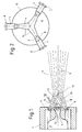
- a main nozzle 2 is arranged in a nozzle housing 1, in which a gas jet supplied through the feed 3 is strongly accelerated (Laval nozzle) before it leaves the main nozzle 2.
- the common longitudinal axis of the rotationally symmetrical nozzle 2 and the consequently rotationally symmetrical exit jet 4 is denoted by 5.
- Two auxiliary nozzles 6, 7 provided according to the invention are assigned to the main nozzle 2 offset by 180 ° relative to one another such that the angles between the longitudinal axis 5 of the main nozzle 2 or the gas or steam jet 4 emerging from the main nozzle and each of the longitudinal axes 8, 9 of the auxiliary nozzles 6, 7 or the auxiliary jets 10, 11 emerging from them, which consist of the same gas or steam as the main gas jet emerging from the main nozzle 2, in the range between 5 ° and 60 °, preferably in the range between 25 ° and 45 °.
- the three gas jets pass through a common chamber 12 in the front side of the nozzle housing 1, which is open in the jet direction, into the material bed 13.
- each of these nozzle assemblies is a nozzle assembly according to FIG. 1.
- Three main jets 5 are formed, each of these main jets are assigned at least two, optimally three auxiliary jets corresponding to the two auxiliary jets 10, 11, and the three grinding jets formed in this way each have a main jet and auxiliary beams assigned to it meet in a union region and around the center 14 of the cylindrical housing 15.
- a separation of solid particles takes place when the three grinding jets meet, but also in each of the three grinding jets, which is why the entire device with the three units A, B, C and the housing 15 is designed so that the three grinding jets meet with great energy and penetrate into each other and the particles are largely evenly distributed in all three gas jets across their cross sections.
- the housing 15 is a relatively short cylindrical drum.
Abstract
Description
Die vorliegende Erfindung befaßt sich mit der Fließbett-Strahlmahlung. In ein Fließbett aus fluidisierten Feststoffpartikeln wird mittels einer Düse ein Dampf- oder vorzugsweise Gasstrahl mit hoher Geschwindigkeit eingeleitet. Im Strahl herrscht ein Unterdruck, weshalb Feststoffpartikel aus dem Fließbett in den Strahl angesaugt werden. Im Strahl werden die angesaugten Feststoffpartikel auf die hohe Geschwindigkeit des Gasstrahls beschleunigt. Dabei erfolgt der für die Zerkleinerung der Feststoffpartikel notwendige Impulsaustausch zwischen den Feststoffpartikeln. Die Geschwindigkeits- und damit Unterdruckverteilung im Gasstrahl ist Anlaß dafür, daß die Partikelverteilung über den Strahlquerschnitt ungleichmäßig ist derart, daß die weit überwiegende Zahl der angesaugten Feststoffpartikel im Randbereich des Gasstrahles verbleiben und im Kernbereich des Gasstrahles relativ wenige Partikel mitgeführt werden. Entsprechend unzulänglich wird die Energie des Gasstrahles für die Prallzerkleinerung genützt. Dies wird als unbefriedigend empfunden, wenn die Prallzerkleinerung allein durch Energieaustausch zwischen den Partikeln im Gasstrahl erfolgt, aber auch dann, wenn auf die Prallzerkleinerung innerhalb des Gasstrahles die eigentliche Prallzerkleinerung erst anschließend dadurch erfolgt, daß die im Gasstrahl suspendierten und teilweise zerkleinerten Feststoffpartikel mit hoher Energie zum Auftreffen auf eine feststehende Prallfläche gebracht werden.The present invention is concerned with fluid bed jet milling. A jet of steam or preferably gas is introduced at high speed into a fluidized bed of fluidized solid particles by means of a nozzle. A negative pressure prevails in the jet, which is why solid particles are sucked into the jet from the fluid bed. In the jet, the sucked solid particles are accelerated to the high speed of the gas jet. The momentum exchange between the solid particles necessary for the comminution of the solid particles takes place. The velocity and therefore vacuum pressure distribution in the gas jet is the reason why the particle distribution over the jet cross-section is uneven such that the vast majority of the sucked solid particles remain in the edge area of the gas jet and relatively few particles are carried in the core area of the gas jet. Accordingly, the energy of the gas jet is used insufficiently for impact crushing. This is perceived as unsatisfactory if the impact crushing takes place solely through the exchange of energy between the particles in the gas jet, but also if the impact crushing within the gas jet takes place only afterwards by the fact that the solid particles suspended and partially crushed in the gas jet are subjected to high energy be brought into contact with a fixed baffle.
Zum Bekanntsein der Prallzerkleinerung mittels eines in ein Fließbett eingebrachten Dampf- bzw. Gasstrahles kann beispielsweise auf die DE-PS 598 421 verwiesen werden. Mit dem dabei gegebenen Problem der unzulänglichen Energieausnutzung befassen sich die DE 42 43 438 A1 und auch die DE-OS 20 40 519 einerseits und die DE 33 38 138 C2 andererseits unter verschiedenen Gesichtspunkten.For the known impact crushing by means of a steam or gas jet introduced into a fluidized bed, reference can be made, for example, to DE-PS 598 421. DE 42 43 438 A1 and also DE-OS 20 40 519, on the one hand, and DE 33 38 138 C2, on the other hand, deal with the problem of inadequate energy utilization from different points of view.
Mit der Verbesserung der Beladung der in ein Fließbett eintretenden Gasstrahlen mit Feststoffpartikeln, die aus dem Fließbett aufgenommen werden, befaßt sich die aus der DE 33 38 138 C2 bekannte Fließbett-Gegenstrahlmühle unter der Zielvorstellung, daß vom in das Fließbett eintretenden Gasstrahl mehr Feststoffpartikel aus dem Fließbett aufgenommen werden. Hierzu sind bei dieser bekannten Fließbett-Gegenstrahlmühle konzentrisch um eine in die Mahlkammer bzw. das Gutbett einmündende Düse mehrere weitere Strahldüsen so angeordnet, daß sich die längsachsen der Gasstrahlen aus der zentralen Hauptdüse und dem konzentrisch zu dieser angeordneten weiteren Strahldüsen in einem Punkt auf der Längsachse des Strahles der Hauptdüse schneiden. Zweck dieser Lösung ist es, im Austrittsbereich der Hauptdüse das Gutbett aufzuwirbeln und so die Aufnahme von Feststoffpartikeln aus dem Fließbett durch den aus der Hauptdüse austretenden Gasstrahl zu verbessern, indem der Gasstrahl aus der Hauptdüse mehr Feststoffpartikel aus dem verwirbelten Gutbett aufnimmt als es bei unverwirbeltem Gutbett möglich wäre.With the improvement of the loading of the gas jets entering a fluidized bed with solid particles which are taken up from the fluidized bed, the fluidized bed counter jet mill known from DE 33 38 138 C2 is concerned with the aim that more solid particles from the gas jet entering the fluidized bed Fluid bed can be included. For this purpose, in this known fluidized bed counter-jet mill, a plurality of further jet nozzles are arranged concentrically around a nozzle opening into the grinding chamber or the material bed in such a way that the longitudinal axes of the gas jets from the central main nozzle and the further jet nozzles arranged concentrically thereto are at one point on the longitudinal axis cut the jet of the main nozzle. The purpose of this solution is to whirl up the material bed in the outlet area of the main nozzle and thus to improve the uptake of solid particles from the fluidized bed by the gas jet emerging from the main nozzle, in that the gas jet from the main nozzle takes up more solid particles from the swirled material bed than it does with non-swirled material beds it is possible.
Die Lösungen nach den beiden anderen Patentpublikationen DE 42 43 438 A1 und DE-OS 20 40 519 sehen zum Zweck der besseren Ausnutzung der Strahlenergie eine Vergleichmäßigung der Verteilung der aus dem Fließbett in den Dampf- oder Gasstrahl - aus Gründen der Vereinfachung wird im Zusammenhang mit der Erfindung und des Standes der Technik von einem Gasstrahl gesprochen, obwohl ein Strahl gemeint ist, der entweder ein Gasstrahl oder ein Dampfstrahl sein kann - angesaugten Feststoffpartikel über den Strahlquerschnitt vor, d.h. Maßnahmen, die bewirken, daß in den Strahlkern zusätzlich Feststoffpartikel aus dem Strahlrandbereich transportiert werden. In der DE-OS 20 40 519 wird die notwendige Partikelbewegung quer zur Strahlrichtung durch mechanische Mittel bewirkt, was einen hohen Bauaufwand ohne optimales Ergebnis zur Folge hat. Im Fall der DE 42 43 438 A1 wird vorgeschlagen, die Größe des Strahlimpulses bei Austritt aus der Strahldüse im Umfangsbereich des Düsenquerschnittes mindestens zweimal zwischen einem Minimal- und einem Maximalwert wechseln zu lassen und die Größe des Strahlimpulses im Kernbereich höchstens auf einem Wert zu halten, der dem Minimalwert des Umfangsbereiches entspricht. Es werden bei dieser Lösung in den Strahlbereichen mit niedrigem Strahlimpuls unmittelbar nach dem Austritt des Strahles aus der Strahldüse Strömungskanäle quer zur Strahlrichtung geschaffen, in denen ein Druckgefälle vom Strahlrand zum Strahlkern besteht, so daß Feststoffpartikel vom Strahlrand in den Strahlkern gesaugt werden. Bewirkt wird das mit einer Vorrichtung, die gekennzeichnet ist durch ein in eine Halterung einsetzbares Düsenelement zur Strahlerzeugung, das mit mindestens zwei über den Querschnitt des Düsenelementes gleichmäßig verteilten Austrittsöffnungen unterschiedlicher Form und Größe versehen ist. Diese Lösung läßt Probleme erwarten, wenn stark unterschiedlichen Betriebsbedingungen Rechnung getragen werden soll.The solutions according to the other two patent publications DE 42 43 438 A1 and DE-OS 20 40 519 see, for the purpose of better utilization of the beam energy, an equalization of the distribution of the fluidized bed in the steam or gas jet - for reasons of simplification is in connection with spoken of the invention and the prior art of a gas jet, although a jet is meant, which can be either a gas jet or a steam jet - sucked solid particles over the beam cross-section, ie measures that cause additional solid particles from the beam edge area in the jet core be transported. In DE-OS 20 40 519 the necessary particle movement transversely to the beam direction is brought about by mechanical means, which results in high construction costs without an optimal result. In the case of DE 42 43 438 A1, it is proposed to have the size of the jet pulse change at least twice between a minimum and a maximum value in the circumferential area of the nozzle cross section upon exit from the jet nozzle and to keep the size of the jet pulse in the core area at most at one value. which corresponds to the minimum value of the peripheral area. With this solution, flow channels are created transversely to the jet direction in the jet areas with a low jet pulse immediately after the jet emerges from the jet nozzle, in which there is a pressure gradient from the jet edge to the jet core, so that solid particles are sucked from the jet edge into the jet core. This is achieved with a device which is characterized by a nozzle element for jet generation which can be inserted into a holder and which has at least two outlet openings of different shape and size which are uniformly distributed over the cross section of the nozzle element is provided. Problems can be expected from this solution if very different operating conditions are to be taken into account.
Während es also bei den vorgenannten Lösungen darum geht, die Beladung des in das Fließbett eintretenden Gasstrahles mit Feststoffpartikeln zu verbessern, indem entweder gemäß DE 33 38 138 C2 die Zahl der aus dem Fließbett aufgenommenen Feststoffpartikel erhöht wird oder gemäß DE 42 43 438 A1 und DE-OS 20 40 519 die Verteilung der Feststoffpartikel über den Strahlquerschnitt vergleichmäßigt wird, wird bei einer anderen bekannten Fließbettstrahlmühle nach WO 90/04457 etwas völlig anderes angestrebt. Es wird nämlich der Energieaustausch zwischen mehreren mit Feststoffpartikeln beladenen Gasstrahlen erhöht, wenn diese Gasstrahlen aufeinanderprallen. Auf die Verteilung der Feststoffpartikel innerhalb jedes der Gasstrahlen oder auf die Beladung des Gasstrahles mit Feststoffpartikeln kommt es bei dieser Lösung überhaupt nicht an.So while the above solutions are concerned with improving the loading of the gas jet entering the fluidized bed with solid particles, either by increasing the number of solid particles taken up from the fluidized bed according to DE 33 38 138 C2 or according to DE 42 43 438 A1 and DE -OS 20 40 519 the distribution of the solid particles over the jet cross-section is evened, something completely different is aimed at in another known fluidized bed jet mill according to WO 90/04457. This is because the energy exchange between a plurality of gas jets loaded with solid particles is increased when these gas jets collide with one another. The distribution of the solid particles within each of the gas jets or the loading of the gas jet with solid particles is irrelevant in this solution.
Die vorliegende Erfindung befaßt sich nun mit dem Problem der Vergleichmäßigung der Verteilung der Feststoffpartikel in einem Gasstrahl, der in ein Fließbett derart eintritt, daß er im Eintreten in das Fließbett aus diesem Feststoffpartikel aufnimmt. Insofern geht die Erfindung insbesondere vom Stand der Technik nach der DE 42 43 438 A1 und DE-OS 20 40 519 aus und sie will bewirken, daß aus dem Fließbett vom Gasstrahl aufgenommene Feststoffpartikel auch in den Kernbereich des Gasstrahles gelangen.The present invention is now concerned with the problem of uniformizing the distribution of the solid particles in a gas jet which enters a fluidized bed in such a way that it picks up from this solid particle as it enters the fluidized bed. In this respect, the invention is based in particular on the state of the art according to DE 42 43 438 A1 and DE-OS 20 40 519 and aims to ensure that solid particles taken up by the gas jet from the fluidized bed also reach the core area of the gas jet.
Aufgabe der vorliegenden Erfindung ist es demzufolge, eine Vorrichtung so auszubilden, daß die Partikelverteilung in einem mit hoher Energie in ein Fließbett einer Fließbettstrahlmühle eingebrachten Gasstrahl über den Strahlquerschnitt und insbesondere die Beladung dieses Gasstrahles mit Feststoffpartikeln aus dem Fließbett auch im Strahlkernbereich mit einfachen und zuverlässig wirkenden Mitteln besser als es bisher erreicht wurde, gewährleistet ist.The object of the present invention is therefore to design a device such that the particle distribution in a gas jet introduced with high energy into a fluid bed of a fluid bed jet mill over the jet cross section and in particular the loading of this gas jet with solid particles from the fluid bed also in the jet core area with simple and reliable acting Means better than it has been achieved so far.
Die Lösung der Aufgabe, die Verteilung der aus einem Fließbett von einem in das Fließbett eintretenden Gasstrahl aufgenommenen Feststoffpartikel über den Gasstrahlquerschnitt in zweckmäßiger Weise zuverlässig gemäß der Erfindung zu vergleichmäßigen, ergibt sich aus dem Anspruch 1, zweckmäßige Ausgestaltungen ergeben sich aus den auf den Anspruch 1 zurückbezogenen Unteransprüchen.The solution to the problem of appropriately reliably comparing the distribution of the solid particles taken up from a fluidized bed by a gas jet entering the fluidized bed over the gas jet cross-section in accordance with the invention results from claim 1, expedient configurations result from related subclaims.
Die Erfindung ist nachfolgend anhand der Zeichnung erläutert. In der Zeichnung zeigen
- Fig. 1
- einen Mittellängsschnitt durch ein Aggregat mit erfindungsgemäß einer Hauptdüse und zwei Hilfsdüsen und
- Fig. 2
- ein zylindrisches Fließbettgehäuse mit drei erfindungsgemäßen Aggregaten gemäß Fig. 1, die dem Gehäuse umfangssymmetrisch zugeordnet sind, d.h. in Umfangsrichtung des Gehäuses gleiche Abstände voneinander haben.
- Fig. 1
- a central longitudinal section through an assembly with a main nozzle and two auxiliary nozzles according to the invention and
- Fig. 2
- a cylindrical fluidized bed housing with three units according to the invention according to FIG. 1, which are assigned to the housing in a symmetrical manner, ie have the same distances from one another in the peripheral direction of the housing.
In einem Düsengehäuse 1 ist eine Hauptdüse 2 angeordnet, in der ein durch die Zuführung 3 zugeführter Gasstrahl stark beschleunigt wird ( Lavaldüse ) , ehe er die Hauptdüse 2 verläßt. Die gemeinsame Längsachse der rotationssymmetrischen Düse 2 und des demzufolge rotationssymmetrischen Austrittsstrahles 4 ist mit 5 bezeichnet. Zwei erfindungsgemäß vorgesehene Hilfsdüsen 6,7 sind um 180° gegeneinander versetzt der Hauptdüse 2 zugeordnet und zwar derart, daß die Winkel zwischen der Längsachse 5 der Hauptdüse 2 bzw. des aus der Hauptdüse austretenden Gas- bzw. Dampfstrahles 4 und jeder der Längsachsen 8,9 der Hilfsdüsen 6,7 bzw. der aus ihnen austretenden Hilfsstrahlen 10,11, die aus dem gleichen Gas oder Dampf bestehen, wie der aus der Hauptdüse 2 austretende Hauptgasstrahl, im Bereich Zwischen 5° und 60°, vorzugsweise im Bereich zwischen 25° und 45°, liegt. Die drei Gasstrahlen gelangen durch eine gemeinsame Kammer 12 in der Stirnseite des Düsengehäuses 1, die in Strahlrichtung offen ist, in das Gutbett 13. Durch den Unterdruck im Hauptgasstrahl werden insbesondere im unmittelbaren Anschluß an die Düse 2 Feststoffpartikel aus dem Fließbett 13 in den Hauptgasstrahl 4 angesaugt und darin auf die Geschwindigkeit des Hauptgasstrahles gebracht. Im Verlauf des Gasstrahles findet ein Energieaustausch zwischen den angesaugten Feststoffpartikeln statt, der diese in kleinere Partikel zerlegt. Ohne die Hilfsdüsen würde die Masse der Partikel überwiegend im Randbereich des (Haupt-)Gasstrahles sich aufhalten und die Prallzerkleinerung würde überwiegend auf diesen Bereich beschränkt sein. Um die aus dem Fließbett 13 angesaugten Partikel nun gleichmäßig über den Querschnitt des Gasstrahles zu verteilen, dringen die Hilfsgasstrahlen aus den Hilfsdüsen in den Hauptgasstrom und "drücken" ein Teil der angesaugten Partikel in den Kernbereich des Hauptgasstrahles.A
Gemäß Fig. 2 sind drei Düsenaggregate A, B, C vorgesehen. Jedes dieser Düsenaggregate ist ein Düsenaggregat gemäß Fig. 1. Es bilden sich drei Hauptstrahlen 5 aus, jedem dieser Hauptstrahlen werden mindestens zwei, optimal drei Hilfsstrahlen entsprechend den beiden Hilfsstrahlen 10, 11 zugeordnet und die drei auf diese Weise gebildeten Mahlstrahlen aus je einem Hauptstrahl und ihm zugeordneten Hilfsstrahlen treffen in einem Vereinigungsbereich und um das Zentrum 14 des zylindrischen Gehäuses 15 zusammen. Eine Zerlegung von Feststoffpartikeln findet beim Aufeinandertreffen der drei Mahlstrahlen, aber auch bereits in jedem der drei Mahlstrahlen statt, weshalb die gesamte Vorrichtung mit den drei Aggregaten A, B, C und dem Gehäuse 15 so ausgelegt ist, daß die drei Mahlstrahlen mit großer Energie aufeinandertreffen und ineinander eindringen und dabei die Partikel in allen drei Gasstrahlen über deren Querschnitte weitgehend gleichmäßig verteilt sind. Das Gehäuse 15 ist eine relativ kurze zylindrische Trommel.2, three nozzle units A, B, C are provided. Each of these nozzle assemblies is a nozzle assembly according to FIG. 1. Three
Claims (7)
Applications Claiming Priority (2)
| Application Number | Priority Date | Filing Date | Title |
|---|---|---|---|
| DE19513034A DE19513034A1 (en) | 1995-04-06 | 1995-04-06 | Fluid bed jet milling device |
| DE19513034 | 1995-04-06 |
Publications (2)
| Publication Number | Publication Date |
|---|---|
| EP0736328A1 true EP0736328A1 (en) | 1996-10-09 |
| EP0736328B1 EP0736328B1 (en) | 1999-08-18 |
Family
ID=7759022
Family Applications (1)
| Application Number | Title | Priority Date | Filing Date |
|---|---|---|---|
| EP96105333A Expired - Lifetime EP0736328B1 (en) | 1995-04-06 | 1996-04-03 | Arrangement for a fluidized bed jet mill |
Country Status (4)
| Country | Link |
|---|---|
| US (1) | US5732893A (en) |
| EP (1) | EP0736328B1 (en) |
| DE (2) | DE19513034A1 (en) |
| ES (1) | ES2136911T3 (en) |
Cited By (2)
| Publication number | Priority date | Publication date | Assignee | Title |
|---|---|---|---|---|
| US6196482B1 (en) | 1999-09-08 | 2001-03-06 | Vishnu Co., Ltd. | Jet mill |
| AT408797B (en) * | 1998-11-11 | 2002-03-25 | Tribovent Verfahrensentwicklg | Method for the reprocessing of hearth ash from combustion plants |
Families Citing this family (15)
| Publication number | Priority date | Publication date | Assignee | Title |
|---|---|---|---|---|
| HRP980257B1 (en) * | 1997-05-28 | 2002-08-31 | Messer Griesheim Gmbh | Apparatus and method for conducting reactions in fluidized particle layers |
| DE19943670A1 (en) * | 1999-09-13 | 2001-03-15 | Roland Nied | Fluidized bed pulverizing process, involving applying centrifugal force to particles in region of at least one fluid jet |
| US6318649B1 (en) * | 1999-10-06 | 2001-11-20 | Cornerstone Technologies, Llc | Method of creating ultra-fine particles of materials using a high-pressure mill |
| US20020054995A1 (en) * | 1999-10-06 | 2002-05-09 | Marian Mazurkiewicz | Graphite platelet nanostructures |
| US6951312B2 (en) * | 2002-07-23 | 2005-10-04 | Xerox Corporation | Particle entraining eductor-spike nozzle device for a fluidized bed jet mill |
| JP4922760B2 (en) * | 2004-07-09 | 2012-04-25 | サンレックス工業株式会社 | Jet mill |
| JP4645972B2 (en) * | 2005-12-14 | 2011-03-09 | 修 廣田 | Injection flame burner and furnace, and flame generation method |
| CN101631622B (en) | 2006-12-14 | 2013-04-24 | 特罗诺克斯有限公司 | An improved jet for in a jet mill micronizer |
| US7959095B2 (en) * | 2007-06-27 | 2011-06-14 | E. I. Du Pont De Nemours And Company | Center-feed nozzle in a contained cylindrical feed-inlet tube for improved fluid-energy mill grinding efficiency |
| CN101648154B (en) * | 2009-09-08 | 2011-06-08 | 武汉理工大学 | Airflow mill of multifunctional fluidized bed |
| CA2848381C (en) | 2011-09-15 | 2020-01-14 | Ablation Technologies, Llc | Devices, systems, and methods for processing heterogeneous materials |
| US9914132B2 (en) * | 2011-09-15 | 2018-03-13 | Michael J. Pilgrim | Devices, systems, and methods for processing heterogeneous materials |
| DE102013000426A1 (en) * | 2013-01-14 | 2014-07-17 | Roland Nied | Method for jet grinding and jet mill for it |
| EP3393669B1 (en) | 2016-12-28 | 2019-09-18 | Houdek, Jan | Device and method for micronization of solid materials |
| US10889744B2 (en) | 2019-04-26 | 2021-01-12 | Signet Aggregates, Llc | Clarification of colloidal suspensions |
Citations (2)
| Publication number | Priority date | Publication date | Assignee | Title |
|---|---|---|---|---|
| DE2628612A1 (en) * | 1976-06-25 | 1977-12-29 | Gvnii Zementnoj Promy Niizemen | Nozzle for high energy gas blast - uses two orthogonally positioned jets to introduce blast material under pressure |
| DE3338138A1 (en) * | 1983-10-20 | 1985-05-09 | Alpine Ag, 8900 Augsburg | FLUID BED COUNTERMILL |
Family Cites Families (10)
| Publication number | Priority date | Publication date | Assignee | Title |
|---|---|---|---|---|
| US238044A (en) * | 1881-02-22 | luckenbach | ||
| US1935344A (en) * | 1931-06-16 | 1933-11-14 | American Pulverizing Corp Camd | Impact pulverizer |
| DE598421C (en) * | 1932-01-18 | 1934-06-13 | Internat Pulverizing Corp | Method and device for impact crushing |
| US2821346A (en) * | 1953-04-23 | 1958-01-28 | Majac Inc | Injector for impact pulverizer or the like |
| GB1143678A (en) * | 1965-12-11 | |||
| DE2040519C2 (en) * | 1970-08-14 | 1984-04-12 | Alpine Ag, 8900 Augsburg | Fluidized bed jet mill |
| DE3891421T1 (en) * | 1988-10-21 | 1990-11-22 | Pt I Organizacii I Technologii | METHOD FOR TREATING GAS JETS OF PACKAGE AND GAS JET PLANT FOR CARRYING IT OUT |
| DD276628B5 (en) * | 1988-11-07 | 1993-12-02 | Zementanlagen Und Maschinenbau | FLUID BED OPPOSED JET MUEHLE |
| US5542613A (en) * | 1992-12-10 | 1996-08-06 | Nied; Roland | Process for impact crushing of solid particles |
| DE4243438C2 (en) * | 1992-12-22 | 1996-06-05 | Hosokawa Alpine Ag | Method and device for fluid bed jet grinding |
-
1995
- 1995-04-06 DE DE19513034A patent/DE19513034A1/en not_active Withdrawn
-
1996
- 1996-03-21 US US08/619,197 patent/US5732893A/en not_active Expired - Lifetime
- 1996-04-03 ES ES96105333T patent/ES2136911T3/en not_active Expired - Lifetime
- 1996-04-03 DE DE59602762T patent/DE59602762D1/en not_active Expired - Lifetime
- 1996-04-03 EP EP96105333A patent/EP0736328B1/en not_active Expired - Lifetime
Patent Citations (2)
| Publication number | Priority date | Publication date | Assignee | Title |
|---|---|---|---|---|
| DE2628612A1 (en) * | 1976-06-25 | 1977-12-29 | Gvnii Zementnoj Promy Niizemen | Nozzle for high energy gas blast - uses two orthogonally positioned jets to introduce blast material under pressure |
| DE3338138A1 (en) * | 1983-10-20 | 1985-05-09 | Alpine Ag, 8900 Augsburg | FLUID BED COUNTERMILL |
Cited By (3)
| Publication number | Priority date | Publication date | Assignee | Title |
|---|---|---|---|---|
| AT408797B (en) * | 1998-11-11 | 2002-03-25 | Tribovent Verfahrensentwicklg | Method for the reprocessing of hearth ash from combustion plants |
| US6196482B1 (en) | 1999-09-08 | 2001-03-06 | Vishnu Co., Ltd. | Jet mill |
| SG80073A1 (en) * | 1999-09-08 | 2001-04-17 | Vishnu Co Ltd | Jet mill |
Also Published As
| Publication number | Publication date |
|---|---|
| DE19513034A1 (en) | 1996-10-10 |
| US5732893A (en) | 1998-03-31 |
| ES2136911T3 (en) | 1999-12-01 |
| EP0736328B1 (en) | 1999-08-18 |
| DE59602762D1 (en) | 1999-09-23 |
Similar Documents
| Publication | Publication Date | Title |
|---|---|---|
| EP0736328A1 (en) | Arrangement for a fluidized bed jet mill | |
| EP0603602B1 (en) | Method and apparatus for jet milling in a fluidised bed | |
| DE102009019255B4 (en) | Spray nozzle arrangement for descaling | |
| DE2711515A1 (en) | CLASSIFYING JET MILL | |
| DE2435181C2 (en) | ||
| DE4440323A1 (en) | Nozzle for a torch head of a plasma spraying unit | |
| EP1080786B1 (en) | Method, device and system for fluidised-bed jet mill | |
| EP0375887B1 (en) | Method and device for cutting and cleaning objects, and for controlled material removal by means of a water-abrasive mixture | |
| DE2928698A1 (en) | Dispenser for liq. bearing particulate abrasive material - has fluid fed through nozzle to mixing chamber to pick up abrasive material in suspension | |
| DE1223237B (en) | Jet mill with flat cylindrical grinding chamber | |
| DE2141291C3 (en) | Spray nozzle to achieve a frustoconical spray mist | |
| DE2822950A1 (en) | DEVICE FOR PNEUMATICALLY DETACHING DUST PARTICLES FROM A DEDUSTING ARRANGEMENT | |
| DE2223441C2 (en) | Device for multi-stage jet grinding | |
| CH682380A5 (en) | Method and apparatus for external cylindrical grinding a cylindrical workpiece. | |
| EP1087055A1 (en) | Hydrocyclone plant | |
| DE19513035C2 (en) | Fluid bed jet grinding | |
| DE4431085C1 (en) | Abrasive water jet cutting process | |
| DE3730597A1 (en) | AIR JET FLOW CRUSHER | |
| EP0601511B1 (en) | Method and device for impact crushing of solid particles | |
| DE2938501C2 (en) | Device for separating fiber material from industrial waste water | |
| EP2383047B9 (en) | Nozzle device | |
| DE3201055A1 (en) | DEVICE FOR TEXTURING AT LEAST ONE CONTINUOUS THREAD MADE OF A MULTIPLE NUMBER OF FILAMENTS | |
| DE19943670A1 (en) | Fluidized bed pulverizing process, involving applying centrifugal force to particles in region of at least one fluid jet | |
| DE1159744B (en) | Jet mill | |
| DE3711761A1 (en) | Device for the swirling of multifilament yarn |
Legal Events
| Date | Code | Title | Description |
|---|---|---|---|
| PUAI | Public reference made under article 153(3) epc to a published international application that has entered the european phase |
Free format text: ORIGINAL CODE: 0009012 |
|
| AK | Designated contracting states |
Kind code of ref document: A1 Designated state(s): DE ES FR GB IT NL |
|
| 17P | Request for examination filed |
Effective date: 19961024 |
|
| GRAG | Despatch of communication of intention to grant |
Free format text: ORIGINAL CODE: EPIDOS AGRA |
|
| GRAG | Despatch of communication of intention to grant |
Free format text: ORIGINAL CODE: EPIDOS AGRA |
|
| 17Q | First examination report despatched |
Effective date: 19981210 |
|
| GRAG | Despatch of communication of intention to grant |
Free format text: ORIGINAL CODE: EPIDOS AGRA |
|
| GRAH | Despatch of communication of intention to grant a patent |
Free format text: ORIGINAL CODE: EPIDOS IGRA |
|
| GRAH | Despatch of communication of intention to grant a patent |
Free format text: ORIGINAL CODE: EPIDOS IGRA |
|
| GRAA | (expected) grant |
Free format text: ORIGINAL CODE: 0009210 |
|
| AK | Designated contracting states |
Kind code of ref document: B1 Designated state(s): DE ES FR GB IT NL |
|
| GBT | Gb: translation of ep patent filed (gb section 77(6)(a)/1977) |
Effective date: 19990818 |
|
| REF | Corresponds to: |
Ref document number: 59602762 Country of ref document: DE Date of ref document: 19990923 |
|
| ET | Fr: translation filed | ||
| ITF | It: translation for a ep patent filed |
Owner name: SOCIETA' ITALIANA BREVETTI S.P.A. |
|
| REG | Reference to a national code |
Ref country code: ES Ref legal event code: FG2A Ref document number: 2136911 Country of ref document: ES Kind code of ref document: T3 |
|
| PGFP | Annual fee paid to national office [announced via postgrant information from national office to epo] |
Ref country code: ES Payment date: 20000412 Year of fee payment: 5 |
|
| PGFP | Annual fee paid to national office [announced via postgrant information from national office to epo] |
Ref country code: FR Payment date: 20000427 Year of fee payment: 5 |
|
| PGFP | Annual fee paid to national office [announced via postgrant information from national office to epo] |
Ref country code: NL Payment date: 20000428 Year of fee payment: 5 |
|
| PLBE | No opposition filed within time limit |
Free format text: ORIGINAL CODE: 0009261 |
|
| STAA | Information on the status of an ep patent application or granted ep patent |
Free format text: STATUS: NO OPPOSITION FILED WITHIN TIME LIMIT |
|
| 26N | No opposition filed | ||
| PG25 | Lapsed in a contracting state [announced via postgrant information from national office to epo] |
Ref country code: ES Free format text: LAPSE BECAUSE OF NON-PAYMENT OF DUE FEES Effective date: 20010404 |
|
| PG25 | Lapsed in a contracting state [announced via postgrant information from national office to epo] |
Ref country code: FR Free format text: THE PATENT HAS BEEN ANNULLED BY A DECISION OF A NATIONAL AUTHORITY Effective date: 20010430 |
|
| PG25 | Lapsed in a contracting state [announced via postgrant information from national office to epo] |
Ref country code: NL Free format text: LAPSE BECAUSE OF NON-PAYMENT OF DUE FEES Effective date: 20011101 |
|
| REG | Reference to a national code |
Ref country code: GB Ref legal event code: IF02 |
|
| NLV4 | Nl: lapsed or anulled due to non-payment of the annual fee |
Effective date: 20011101 |
|
| REG | Reference to a national code |
Ref country code: FR Ref legal event code: ST |
|
| REG | Reference to a national code |
Ref country code: ES Ref legal event code: FD2A Effective date: 20030303 |
|
| PG25 | Lapsed in a contracting state [announced via postgrant information from national office to epo] |
Ref country code: IT Free format text: LAPSE BECAUSE OF NON-PAYMENT OF DUE FEES;WARNING: LAPSES OF ITALIAN PATENTS WITH EFFECTIVE DATE BEFORE 2007 MAY HAVE OCCURRED AT ANY TIME BEFORE 2007. THE CORRECT EFFECTIVE DATE MAY BE DIFFERENT FROM THE ONE RECORDED. Effective date: 20050403 |
|
| PGFP | Annual fee paid to national office [announced via postgrant information from national office to epo] |
Ref country code: DE Payment date: 20150506 Year of fee payment: 20 Ref country code: GB Payment date: 20150424 Year of fee payment: 20 |
|
| REG | Reference to a national code |
Ref country code: DE Ref legal event code: R071 Ref document number: 59602762 Country of ref document: DE |
|
| REG | Reference to a national code |
Ref country code: GB Ref legal event code: PE20 Expiry date: 20160402 |
|
| PG25 | Lapsed in a contracting state [announced via postgrant information from national office to epo] |
Ref country code: GB Free format text: LAPSE BECAUSE OF EXPIRATION OF PROTECTION Effective date: 20160402 |