EP0736280B1 - Warenträger zur Präsentation von Gegenständen - Google Patents
Warenträger zur Präsentation von Gegenständen Download PDFInfo
- Publication number
- EP0736280B1 EP0736280B1 EP19960200896 EP96200896A EP0736280B1 EP 0736280 B1 EP0736280 B1 EP 0736280B1 EP 19960200896 EP19960200896 EP 19960200896 EP 96200896 A EP96200896 A EP 96200896A EP 0736280 B1 EP0736280 B1 EP 0736280B1
- Authority
- EP
- European Patent Office
- Prior art keywords
- rack
- door
- closing
- sidewalls
- articles
- Prior art date
- Legal status (The legal status is an assumption and is not a legal conclusion. Google has not performed a legal analysis and makes no representation as to the accuracy of the status listed.)
- Expired - Lifetime
Links
- 238000005096 rolling process Methods 0.000 claims description 9
- 230000000712 assembly Effects 0.000 description 12
- 238000000429 assembly Methods 0.000 description 12
- 238000005192 partition Methods 0.000 description 3
- 241000208125 Nicotiana Species 0.000 description 2
- 235000002637 Nicotiana tabacum Nutrition 0.000 description 2
- 235000009508 confectionery Nutrition 0.000 description 2
Images


Classifications
-
- E—FIXED CONSTRUCTIONS
- E05—LOCKS; KEYS; WINDOW OR DOOR FITTINGS; SAFES
- E05C—BOLTS OR FASTENING DEVICES FOR WINGS, SPECIALLY FOR DOORS OR WINDOWS
- E05C3/00—Fastening devices with bolts moving pivotally or rotatively
- E05C3/02—Fastening devices with bolts moving pivotally or rotatively without latching action
- E05C3/06—Fastening devices with bolts moving pivotally or rotatively without latching action with operating handle or equivalent member moving otherwise than rigidly with the bolt
- E05C3/10—Fastening devices with bolts moving pivotally or rotatively without latching action with operating handle or equivalent member moving otherwise than rigidly with the bolt the handle or member moving essentially in a plane substantially parallel to the wing or frame
-
- A—HUMAN NECESSITIES
- A47—FURNITURE; DOMESTIC ARTICLES OR APPLIANCES; COFFEE MILLS; SPICE MILLS; SUCTION CLEANERS IN GENERAL
- A47F—SPECIAL FURNITURE, FITTINGS, OR ACCESSORIES FOR SHOPS, STOREHOUSES, BARS, RESTAURANTS OR THE LIKE; PAYING COUNTERS
- A47F9/00—Shop, bar, bank or like counters
- A47F9/02—Paying counters
- A47F9/04—Check-out counters, e.g. for self-service stores
-
- E—FIXED CONSTRUCTIONS
- E05—LOCKS; KEYS; WINDOW OR DOOR FITTINGS; SAFES
- E05B—LOCKS; ACCESSORIES THEREFOR; HANDCUFFS
- E05B65/00—Locks or fastenings for special use
- E05B65/08—Locks or fastenings for special use for sliding wings
- E05B65/0811—Locks or fastenings for special use for sliding wings the bolts pivoting about an axis perpendicular to the wings
Definitions
- a rack comprising a rack for displaying articles, the rack comprising a rear wall, two sidewalls, a display space having an open front side for displaying said articles being provided between the sidewalls and a door with which the open front side can be closed off and released.
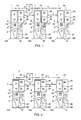
- Fig. 2 is a top plan view of a number of juxtaposted assemblies, each assembly consisting of a checkout unit and an associated display rack 22'.
- a top portion of the rack 22' is located above the checkout unit 1.
- the relevant top portion of the rack 22' extends above the conveying apparatus 2 of the checkout unit 1.
- the top portions 36, 38 of the sidewalls 24, 26 between which the display space 32 is located and the display space 32 itself are located partly above the checkout unit 1.
- the rack therefore, provides a solution to the problem that it extends above the conveying apparatus 2. This would mean that a portion of the conveying apparatus 2 cannot be utilised for conveying articles in the direction of the cash register 8.
- the rack according to the invention provides a solution to the problem as well, as will be explained hereinafter.
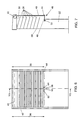
- Fig. 4 is a front view of the rack 22' in the direction of the arrow A as shown in Fig. 2.
- Fig. 5 shows a cross section of the rack 22' according to Fig. 4.
- the rack 22' comprises the two sidewalls 24, 26 and the rear wall 28.
- Located in the display space 32 are a number of inclined product supports 36 for displaying the articles.
- the rack 22' further comprises a rolling door 40 having a roll-up shaft 42, shown in a dotted line and located at the top side of the rack.
- the rolling door 40 is in its rolled-up position. This renders the display space 32 accessible for viewing and taking out the articles.
- the complete width of the conveying apparatus 2 can advantageously be utilized. After all, the area 49, hatched in Fig. 5, can be used for the conveyance of articles located on the conveying apparatus 2.
- the rack comprises a horizontally oriented cross profile 50 which extends between the sidewalls 24 and 26 and is fixedly connected thereto.
- the closing shelf 46 comprises a U-shaped profile having a first and second wall part 52, 54, each being connected to a connecting part 56 at a top side.
- Fig. 8 shows a section of the closing shelf 46 according to the line VII of Fig. 6.
- the first wall part 52 is located on the outside of the rack and has its outside provided with a locking mechanism 58 which, in use, can cooperate in a manner known per se with the bottom rail 44 of the rolling door 40.
- the locking mechanism comprises for instance an opening 60 into which a key can be inserted for connecting the locking mechanism 58 to the bottom rail 44 in a detachable manner.
- the closing shelf comprises two pins 62, 64, separated from each other in horizontal direction and extending in the direction of movement of the closing shelf.
- the cross profile 50 is provided with two openings 66, 68.
- the pins 62, 64, slidable in the longitudinal direction of the pins, are received in the openings 66, 68 respectively.
- Each pin consists of a hollow tube 70 accommodating a threaded shaft 72.
- the first and second wall parts 52, 54 are each provided with an opening 74 through which the shaft 72 extends.
- the locking mechanism 58 too, is provided with an opening 76 through which the shaft 72 extends.
- the ends of the shaft 72 each comprise a nut 78 by means of which the locking mechanism 58 is connected to the closing shelf.
- the tube 70 has a diameter greater than the openings 74. Because each tube 70 can be moved back and forth through the openings 66 and 68 respectively, the entire closing shelf is accommodated in the rack so as to be movable in horizontal direction.
- the assembly of checkout unit and rack may comprise a second rack 80, see also Fig. 9.
- the second rack too, comprises a rear wall 82 and two sidewalls 84.
- the rack further comprises an open front side 86 which, in this case, extends from the top side to near the bottom side of the rack 80.
- a display space 88 also extending from the top side to the bottom side of the rack 80. Included in the display space 88 are again a number of superimposed product supports 90, extending in horizontal direction between the sidewalls of the rack.
Landscapes
- Engineering & Computer Science (AREA)
- Mechanical Engineering (AREA)
- Display Racks (AREA)
- Freezers Or Refrigerated Showcases (AREA)
Claims (12)
- Gestell (22') zur Auslage von Gegenständen, wobei das Gestell folgendes umfasst: eine Rückwand (28), zwei Seitenwände (24, 26), einen Auslageraum (32) mit einer offenen Vorderseite (30) zur Auslage der genannten Gegenstände zwischen den Seitenwänden in einem oberen Abschnitt davon, und eine Tür (40), mit der die offene Vorderseite (30) verschlossen und geöffnet werden kann, dadurch gekennzeichnet, dass die Breite des oberen Abschnitts (36, 38) der Seitenwände größer ist als die Breite eines unteren Abschnitts der Seitenwände, so dass ein Teil des Auslageraums (32) übersteht, und dadurch, dass das Gestell (22') ferner eine Verschlussplatte (46) umfasst, die in einer nicht vertikalen Ebene zwischen einer ersten und einer zweiten Position beweglich ist, wobei sich die Verschlussplatte (46) in der ersten Position im nicht überstehenden Abschnitt des Auslageraums befindet und die Verschlussplatte (46) sich in der zweiten Position in Richtung auf die Vorderseite des Teils des Auslageraums erstreckt, der übersteht, so dass die Verschlussplatte (46) auf das untere Ende der Tür (40) trifft, wenn die Tür die offene Vorderseite (30) des Auslageraums (32) verschließt.
- Gestell nach Anspruch 1, dadurch gekennzeichnet, dass die Verschlussplatte (46) in einer horizontalen Ebene zwischen der ersten und der zweiten Position beweglich ist.
- Gestell nach Anspruch 2, dadurch gekennzeichnet, dass die Tür (40) aus einer Rolltür mit einer Aufrollwelle (42) besteht, die sich an der Oberseite des Gestells befindet, so dass die Rolltür (40) von der Oberseite nach unten abgerollt werden kann, um die offene Vorderseite (30) zu verschließen.
- Gestell nach Anspruch 3, dadurch gekennzeichnet, dass die Verschlussplatte (46) einen Verriegelungsmechanismus (58) beinhaltet, über den die Verschlussplatte in der zweiten Position mit der verschlossenen Tür (40) verbunden werden kann.
- Gestell nach Anspruch 4, dadurch gekennzeichnet, dass die Verschlussplatte (46) ein U-förmiges Profil umfasst, mit einem ersten (52) und einem zweiten Wandteil (54), deren Oberseite mit einem Verbindungsteil (56) verbunden ist.
- Gestell nach Anspruch 5, dadurch gekennzeichnet, dass sich das erste Wandteil (52) auf der Außenseite des Gestells befindet und den genannten Verriegelungsmechanismus (58) auf seiner Außenseite trägt.
- Gestell nach Anspruch 6, dadurch gekennzeichnet, dass die Verschlussplatte (46) zwischen dem ersten und dem zweiten Wandteil (52, 54) Stifte (62, 64) aufweist, die in horizontaler Richtung voneinander beabstandet sind und in die Bewegungsrichtung der Verschlussplatte (46) verlaufen, wobei das Gestell ferner ein Querprofil (50) umfasst, das sich zwischen den beiden Seitenwänden (24, 26) erstreckt und mit ihnen verbunden ist, wobei das Querprofil (50) zwei Öffnungen (66, 68) hat, in denen die Stifte (62, 64) gleitfähig aufgenommen werden.
- Gestell nach Anspruch 7, dadurch gekennzeichnet, dass das erste und das zweite Wandteil (52, 54) jeweils mit zwei Öffnungen (74) versehen sind, wobei jeder Stift (62, 64) durch eine Öffnung (74) des ersten Wandteils (52) und durch eine Öffnung (74) des zweiten Wandteils (54) verläuft und die Verriegelungsvorrichtung (58) über die Stifte (62, 64) mit der Verschlussplatte (46) verbunden ist.
- Gestell nach einem der Ansprüche 1 bis 8, dadurch gekennzeichnet, dass das Gestell eine zweite offene Vorderseite (86) und eine zweite Tür (92) umfasst, während zwischen den Seitenwänden (84) ein zweiter Auslageraum (88) für die Auslage der genannten Gegenstände vorhanden ist, wobei die zweite offene Vorderseite (86) mit der zweiten Tür (92) verschlossen und geöffnet werden kann und die beiden Auslageräume (32, 88) auf entgegengesetzten Seiten der Rückwand (28) angeordnet sind.
- Baugruppe aus einer Kasseneinheit (1) und einem Gestell (22') zur Auslage von Gegenständen nach einem der Ansprüche 1 bis 9, wobei die Kasseneinheit eine Registrierkasse (8) und eine Beförderungseinrichtung (2) zur Beförderung von zu registrierenden Gegenständen in Richtung der Registrierkasse (8) umfasst, dadurch gekennzeichnet, dass sich das genannte überstehende Teil der Seitenwände (24, 26) und der Auslageraum (32) oberhalb der Beförderungseinrichtung (2) befinden.
- Baugruppe nach Anspruch 10, dadurch gekennzeichnet, dass sich die Verschlussplatte (46) in der zweiten Position oberhalb der Beförderungseinrichtung (2) erstreckt und in der ersten Position neben der Beförderungseinrichtung (2) befindet.
- Baugruppe nach Anspruch 10 oder 11, dadurch gekennzeichnet, dass die Kasseneinheit (1) und das Gestell (22') trennbar miteinander verbunden sind.
Applications Claiming Priority (2)
| Application Number | Priority Date | Filing Date | Title |
|---|---|---|---|
| NL1000017A NL1000017C2 (nl) | 1995-04-03 | 1995-04-03 | Samenstel van een kassablok en een rek. |
| NL1000017 | 1995-04-03 |
Publications (2)
| Publication Number | Publication Date |
|---|---|
| EP0736280A1 EP0736280A1 (de) | 1996-10-09 |
| EP0736280B1 true EP0736280B1 (de) | 2002-03-06 |
Family
ID=19760800
Family Applications (1)
| Application Number | Title | Priority Date | Filing Date |
|---|---|---|---|
| EP19960200896 Expired - Lifetime EP0736280B1 (de) | 1995-04-03 | 1996-04-02 | Warenträger zur Präsentation von Gegenständen |
Country Status (4)
| Country | Link |
|---|---|
| EP (1) | EP0736280B1 (de) |
| AU (1) | AU704492B2 (de) |
| DE (1) | DE69619573T2 (de) |
| NL (1) | NL1000017C2 (de) |
Family Cites Families (5)
| Publication number | Priority date | Publication date | Assignee | Title |
|---|---|---|---|---|
| DE2734499A1 (de) * | 1977-07-30 | 1979-02-08 | Bat Cigarettenfab Gmbh | Warentraeger |
| US4645036A (en) * | 1983-12-12 | 1987-02-24 | Nestler Richard F | Product dispenser |
| DE4231941C2 (de) * | 1992-09-24 | 1994-11-24 | Bat Cigarettenfab Gmbh | Vorrichtung zur Präsentation und Ausgabe von Packungen, insbesondere Cigarettenpackungen |
| DE9215895U1 (de) * | 1992-11-24 | 1993-02-04 | Olsen, Sven, 2390 Flensburg | Zigarettenträger |
| ATE171051T1 (de) * | 1995-04-11 | 1998-10-15 | Vanderdonckt Paul E A | Vorrichtung zur bevorratung von zigarettenpackungen in einer warenabrechnungsablage |
-
1995
- 1995-04-03 NL NL1000017A patent/NL1000017C2/xx not_active IP Right Cessation
-
1996
- 1996-04-02 EP EP19960200896 patent/EP0736280B1/de not_active Expired - Lifetime
- 1996-04-02 DE DE1996619573 patent/DE69619573T2/de not_active Expired - Fee Related
- 1996-04-03 AU AU50476/96A patent/AU704492B2/en not_active Ceased
Also Published As
| Publication number | Publication date |
|---|---|
| NL1000017C2 (nl) | 1996-10-04 |
| EP0736280A1 (de) | 1996-10-09 |
| DE69619573D1 (de) | 2002-04-11 |
| AU5047696A (en) | 1996-10-17 |
| DE69619573T2 (de) | 2002-08-29 |
| AU704492B2 (en) | 1999-04-22 |
Similar Documents
| Publication | Publication Date | Title |
|---|---|---|
| US5468942A (en) | Dispensing device for hand scanners accessible from two sides | |
| US5168961A (en) | Supermarket with self-service checkout | |
| US5497853A (en) | Labor-saving consolidated checkout system | |
| US6416270B1 (en) | Automated library kiosk | |
| US7967112B2 (en) | Check stand with a two belted input and a slidable scanner | |
| US7114650B2 (en) | Retail products storage and dispensing apparatus and method | |
| US4789048A (en) | Checkout counter | |
| US5316107A (en) | Device for checking out goods | |
| US5478183A (en) | Article selector and method | |
| US5884728A (en) | Assembly for checking and registering purchases in a self-service sales point | |
| US1242872A (en) | Self-serving store. | |
| US20110253778A1 (en) | Self Checkout Stands | |
| US5215213A (en) | Item storage and dispensing apparatus | |
| CA2222897C (en) | Front end merchandiser with check-out lane blocker | |
| CN111971716A (zh) | 可食用产品和/或耐用品的自动分配器 | |
| EP0736280B1 (de) | Warenträger zur Präsentation von Gegenständen | |
| RU2541942C2 (ru) | Гибкий контрольно-кассовый пункт с возможностью быстрого и упрощенного перехода от обычного использования с помощью работника к использования самоконтроля и наоборот | |
| US1544949A (en) | Belf-bbwvtwo store | |
| US6431371B1 (en) | Newsstand display module | |
| US2217647A (en) | Means for filling orders in retail stores | |
| JP6673626B1 (ja) | ショーケース | |
| EP1141906A1 (de) | Hilfsvorrichtung zum hinzufügen zu einer abgabevorrichtung für artikel und kombination von einer abgabevorrichtung und einer hilfsvorrichtung | |
| JP3623126B2 (ja) | 商品データ登録装置 | |
| KR100240772B1 (ko) | 자동판매장치 | |
| US1703477A (en) | Store service |
Legal Events
| Date | Code | Title | Description |
|---|---|---|---|
| PUAI | Public reference made under article 153(3) epc to a published international application that has entered the european phase |
Free format text: ORIGINAL CODE: 0009012 |
|
| AK | Designated contracting states |
Kind code of ref document: A1 Designated state(s): BE DE FR GB LU NL |
|
| 17P | Request for examination filed |
Effective date: 19970403 |
|
| RAP1 | Party data changed (applicant data changed or rights of an application transferred) |
Owner name: VAN NELLE TABAK NEDERLAND B.V. |
|
| 17Q | First examination report despatched |
Effective date: 19991124 |
|
| RTI1 | Title (correction) |
Free format text: A RACK FOR DISPLAYING ARTICLES |
|
| RTI1 | Title (correction) |
Free format text: A RACK FOR DISPLAYING ARTICLES |
|
| GRAG | Despatch of communication of intention to grant |
Free format text: ORIGINAL CODE: EPIDOS AGRA |
|
| GRAG | Despatch of communication of intention to grant |
Free format text: ORIGINAL CODE: EPIDOS AGRA |
|
| GRAH | Despatch of communication of intention to grant a patent |
Free format text: ORIGINAL CODE: EPIDOS IGRA |
|
| GRAH | Despatch of communication of intention to grant a patent |
Free format text: ORIGINAL CODE: EPIDOS IGRA |
|
| REG | Reference to a national code |
Ref country code: GB Ref legal event code: IF02 |
|
| GRAA | (expected) grant |
Free format text: ORIGINAL CODE: 0009210 |
|
| AK | Designated contracting states |
Kind code of ref document: B1 Designated state(s): BE DE FR GB LU NL |
|
| REF | Corresponds to: |
Ref document number: 69619573 Country of ref document: DE Date of ref document: 20020411 |
|
| ET | Fr: translation filed | ||
| PLBE | No opposition filed within time limit |
Free format text: ORIGINAL CODE: 0009261 |
|
| STAA | Information on the status of an ep patent application or granted ep patent |
Free format text: STATUS: NO OPPOSITION FILED WITHIN TIME LIMIT |
|
| 26N | No opposition filed |
Effective date: 20021209 |
|
| PGFP | Annual fee paid to national office [announced via postgrant information from national office to epo] |
Ref country code: GB Payment date: 20080201 Year of fee payment: 13 |
|
| PGFP | Annual fee paid to national office [announced via postgrant information from national office to epo] |
Ref country code: LU Payment date: 20080414 Year of fee payment: 13 Ref country code: DE Payment date: 20080612 Year of fee payment: 13 |
|
| PGFP | Annual fee paid to national office [announced via postgrant information from national office to epo] |
Ref country code: BE Payment date: 20080212 Year of fee payment: 13 |
|
| PGFP | Annual fee paid to national office [announced via postgrant information from national office to epo] |
Ref country code: NL Payment date: 20080131 Year of fee payment: 13 |
|
| PGFP | Annual fee paid to national office [announced via postgrant information from national office to epo] |
Ref country code: FR Payment date: 20080423 Year of fee payment: 13 |
|
| BERE | Be: lapsed |
Owner name: *VAN NELLE TABAK NEDERLAND B.V. Effective date: 20090430 |
|
| GBPC | Gb: european patent ceased through non-payment of renewal fee |
Effective date: 20090402 |
|
| NLV4 | Nl: lapsed or anulled due to non-payment of the annual fee |
Effective date: 20091101 |
|
| REG | Reference to a national code |
Ref country code: FR Ref legal event code: ST Effective date: 20091231 |
|
| PG25 | Lapsed in a contracting state [announced via postgrant information from national office to epo] |
Ref country code: DE Free format text: LAPSE BECAUSE OF NON-PAYMENT OF DUE FEES Effective date: 20091103 |
|
| PG25 | Lapsed in a contracting state [announced via postgrant information from national office to epo] |
Ref country code: NL Free format text: LAPSE BECAUSE OF NON-PAYMENT OF DUE FEES Effective date: 20091101 |
|
| PG25 | Lapsed in a contracting state [announced via postgrant information from national office to epo] |
Ref country code: GB Free format text: LAPSE BECAUSE OF NON-PAYMENT OF DUE FEES Effective date: 20090402 Ref country code: FR Free format text: LAPSE BECAUSE OF NON-PAYMENT OF DUE FEES Effective date: 20091222 |
|
| PG25 | Lapsed in a contracting state [announced via postgrant information from national office to epo] |
Ref country code: BE Free format text: LAPSE BECAUSE OF NON-PAYMENT OF DUE FEES Effective date: 20090430 |
|
| PG25 | Lapsed in a contracting state [announced via postgrant information from national office to epo] |
Ref country code: LU Free format text: LAPSE BECAUSE OF NON-PAYMENT OF DUE FEES Effective date: 20090402 |