EP0735763B1 - System für Information auf Anfrage - Google Patents
System für Information auf Anfrage Download PDFInfo
- Publication number
- EP0735763B1 EP0735763B1 EP95200819A EP95200819A EP0735763B1 EP 0735763 B1 EP0735763 B1 EP 0735763B1 EP 95200819 A EP95200819 A EP 95200819A EP 95200819 A EP95200819 A EP 95200819A EP 0735763 B1 EP0735763 B1 EP 0735763B1
- Authority
- EP
- European Patent Office
- Prior art keywords
- data
- information
- storage medium
- video
- end device
- Prior art date
- Legal status (The legal status is an assumption and is not a legal conclusion. Google has not performed a legal analysis and makes no representation as to the accuracy of the status listed.)
- Expired - Lifetime
Links
Images


Classifications
-
- H—ELECTRICITY
- H04—ELECTRIC COMMUNICATION TECHNIQUE
- H04N—PICTORIAL COMMUNICATION, e.g. TELEVISION
- H04N21/00—Selective content distribution, e.g. interactive television or video on demand [VOD]
- H04N21/20—Servers specifically adapted for the distribution of content, e.g. VOD servers; Operations thereof
- H04N21/25—Management operations performed by the server for facilitating the content distribution or administrating data related to end-users or client devices, e.g. end-user or client device authentication, learning user preferences for recommending movies
-
- H—ELECTRICITY
- H04—ELECTRIC COMMUNICATION TECHNIQUE
- H04N—PICTORIAL COMMUNICATION, e.g. TELEVISION
- H04N7/00—Television systems
- H04N7/16—Analogue secrecy systems; Analogue subscription systems
- H04N7/173—Analogue secrecy systems; Analogue subscription systems with two-way working, e.g. subscriber sending a programme selection signal
- H04N7/17309—Transmission or handling of upstream communications
- H04N7/17336—Handling of requests in head-ends
-
- H—ELECTRICITY
- H04—ELECTRIC COMMUNICATION TECHNIQUE
- H04N—PICTORIAL COMMUNICATION, e.g. TELEVISION
- H04N7/00—Television systems
- H04N7/16—Analogue secrecy systems; Analogue subscription systems
- H04N7/173—Analogue secrecy systems; Analogue subscription systems with two-way working, e.g. subscriber sending a programme selection signal
- H04N7/17309—Transmission or handling of upstream communications
- H04N7/17318—Direct or substantially direct transmission and handling of requests
Definitions
- the present invention provides a system for serving information data to one or more end devices of one or more users according to claim 1, the preamble of which is known for instance from EP-A-624 039 or EP-A-625 857.
- This system according to the present invention provides a sort of platform and can operatively be connected to an end user through a public network, can operate as a stand alone system operatively connected to end devices, in which latter case the system according to the present invention is also provided with navigation devices for presenting possible choices for an end user entering the system.
- the routing means comprise at least one ATM switch.
- ATM Asynchronous Transfer Mode
- the basics and standards of ATM are laid down in recommendations I.150 and I.327 as published in March 1993 by the International Telecommunication Union.
- ATM is generally used for addressing a specific packet-oriented transfer mode which uses asynchronous time division multiplexing techniques.
- the multiplexed information flow is organized into blocks of fixed size, where said blocks are referred to as cells.
- a cell consists of an information field and a header.
- the primary role of the header is to identify cells belonging to the same virtual channel within the asynchronous time division multiplex.
- said information data is video and/or audio data although the present invention is not limited to this application.
- a system according to the present invention may also comprise applications for video-games, library functions, databanks etc., although a first promising application field relates to video on demand services.
- the demand data preferably includes a public address to be assigned to the selected information data.
- the managing means provide program data for information retrieval to the end device, so that an end device will be downloaded with such program data from the system.
- This feature provides the additional advantage that the end device only needs to include very little software for starting up purposes etc.
- the information services system according to the present invention may comprise only one storage medium unit (and even one end device), the system according to the present invention preferably comprises at least one second storage medium unit.
- the managing means comprise a table for storing data representing information data allocation to the first and second storage medium unit on basis of demand data from an end device. In this way the managing means manage the switching of the ATM switch for establishing virtual channels between the end device and the storage medium unit.
- the storage medium unit according to the present invention comprises;
- the information server system in a video and/or audio data application is capable of providing still mode, fast forwards mode, reverse mode, fast reverse mode as in VCR (video cassette recorder) and a mosaic mode operation.
- VCR video cassette recorder
- video and/or audio data is divided in a predetermined number of data groups arranged in a sequence different from the original sequence.
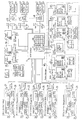
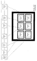
- Fig. 1 shows an entire configuration of a preferred embodiment of an interactive communication system according to the present invention, comprising, : an ATM switch 1 (as example only: ForeRunnerTM ASX-200 of Fore Systems Inc., Warrendale, Pennsylvania, USA) ; storage medium units 20 (SMU); end devices 40; a system manager 60 and navigation devices 30.
- ATM switch 1 connects the storage medium units 20, the end devices 40, the system manager 60 and the navigation devices 30 to each other, selectively, by using virtual channel connections and data is transferred to and from these components in a form of ATM packets consisting of a 5 byte cell header including routing information and a 48 byte information field through ATM user/network interfaces provided between each device and ATM switch 1.
- ATM switch 1 has a conversion table of routing information such as Virtual Channel Identifier and by changing the routing information of each incoming ATM packet to the routing information designating the output virtual channel, the ATM packet can be transferred to the correct destination.
- ATM switches are known and further explanation is omitted here.
- VOD video-on-demand
- video signals and/or audio signals are stored in SMU's 20.
- SMU's 20 video signals and/or audio signals are stored in SMU's 20.
- end devices 40 are set top boxes, each of which can communicate with the navigation devices 30, the system manager 60 and can decode video data (preferably compressed according to the MPEG-2 standard) and/or audio data from a SMU 20, and supply decoded video signal and/or audio signal to a monitor 43 and/or a speaker system 42.
- Each set top box or end device 40 has an input device 44, for example a keyboard or remote control, connected thereto.
- a set top box is provided with a graphical processor unit 49 (see Fig. 9) for generating graphical data to monitor 43 to facilitate interaction with the user.
- the data for the graphical processing unit is supplied by the system manager through the ATM packets.
- a viewer can input instructions through the keyboard 44 or other suitable input device through the set top box 40.
- Navigation devices 30 can provide information on available video programs to any one of the set top boxes 40. Such information can be represented on the monitor 43 of the set top box 40 in a graphical way or by text, or by a combination thereof. Available video programs are video programs which can be selected by a viewer. Such requestable information will hereinafter be referred to as service items. An embodiment of a navigation device 30 is described below in more detail.
- the system manager 60 manages operation of the interactive communication system by managing the operation of the ATM switch 1. An embodiment of the system manager 60 will be described below in more detail.
- a major feature of an interactive communication system is, that there are no restrictions on the hardware used or the operating system installed.
- Each set of communication operations is preceded by transmission of a control software program dedicated to such set of operations to a receiving and/or transmitting component, so that the receiving and/or transmitting component can optimally handle the incoming and/or outgoing communication following this down-load of said control software program.
- At least one of the SMU's 20 is an archive SMU.
- the other SMU's 20 are delivery SMU's.
- the archive SMU stores many kinds of control software programs, video data and/or audio data.
- An archive SMU may comprise as memory means a tape or MO disc, while a delivery SMU preferably comprises an agile hard disc or MO disc as memory means.
- a MO disc is less agile than a hard disc but more agile than a tape.
- Each of the delivery SMU's stores separate parts of the data of the archive SMU. While the archive SMU may also be used as a SMU for delivery purposes, the delivery SMU's are used for VOD service.
- the system manager 60 downloads control software program to the archive SMU and the delivery SMU for a copy operation from the archive SMU to one of the delivery SMU's at the beginning of or in advance of a video on demand service.
- the installation of a delivery SMU by the archive SMU is shown in more detail in fig. 18.
- the delivery SMU stores necessary video data from the archive SMU according to a command for the copy operation from the system manager 60, and in particular from the storage medium manager 62.
- the system manager 60 When the system manager 60 receives the demand data from an end device 40, the system manager 60 outputs to the ATM switch 1 distribution control data including information of virtual channels for the selected video data produced from the received demand data and an address of the end device 40. Next, the delivery SMU outputs the selected video data with the routing information for this end device 40.
- a software program for write-in operation is down-loaded from the system manager 60 to the RAM 24 of the SMU 20 (see Fig. 2) before copy operation of the video data is performed.
- the CPU 22 of the SMU 20 controls write-in operation of the physical storage medium 21 according to the software program for write-in operation stored in the RAM 24.
- the software program for write-in operation in the RAM 24 is replaced with a software program for read-out operation by down-load from the system manager 60 before video service starts.
- the CPU 22 controls read-out operation of the physical storage medium 21 according to the software program for read-out operation in video service.
- the interactive communication system preferably comprises a plurality of (delivery) SMU's.
- the necessary video and/or audio data of a particular video and/or audio program is only copied from the archive SMU to one of the delivery SMU's, if the number of end devices 40 with the possibility to select the particular video and/or audio program is smaller than a predetermined number.
- the necessary video and/or audio data is also copied from the archive SMU or from the above delivery SMU to one or more of the other delivery SMU's, if more than the predetermined number of end devices have the possibility to select the particular video or audio program.
- the predetermined number can be determined based on certain statistics or real time monitoring of the number of end devices 40 requesting the particular video and/or audio program at a specific point in time.
- the preferred embodiment of the present invention provides for the possibility that the number of end users is monitored in run time and that the configuration will dynamically change to prevent the system from overloading.
- a new delivery SMU can be loaded from the archive SMU or another delivery SMU.
- the system manager 60 preferably outputs backup control data, for the situation that one of the delivery SMU's malfunctions. Selected video and/or audio data is then output by another delivery SMU, which is not malfunctioning and is selected according to said backup control data.
- the conversion table of virtual channels in the ATM switch 1 is updated by the system manager 60 so that the input virtual channel of a possibly malfunctioning delivery SMU is changed to the virtual channel of another delivery SMU to provide the same video and/or audio data from the second SMU.
- a user selects the desired navigation service and connects the end device 40 to a navigation device 30 providing the desired navigation service.
- Navigation data including a software program for displaying a menu of service items and identification data corresponding to each service item is downloaded preferably beforehand from at least one navigation device 30 selected by the end device 40.
- the monitor 43 of end device 40 displays such a menu of the available service items and, if necessary, corresponding identification data thereof.
- a menu from navigation device 30 may comprise video and/or audio information and control data, either in graphical form, textual format or a combination thereof, to facilitate the choice for the end user.
- the identification data is supplied to the system manager 60 by the end device 40 via ATM switch 1.
- Such identification data may be a public address in case that the system manager 60 is connected to public ATM network.
- the navigation data may further include video data obtained from SMU 20 or navigation device 30.
- the navigation data down-loaded from a navigation device 30 can also contain information on other selectable navigation devices 30.
- an end device 40 can be connected to a navigation device through a public ATM switch, in which case such a navigation device can be selected through a public address. Through such a public navigation device it would also be possible to choose other navigation devices via the first publication navigation device.
- the system manager 60 down-loads a VOD-software program for end devices 40 corresponding to a selected video program to the end device 40, after the system manager 60 receives identification data from the set top box 40.
- the system manager 60 also downloads a VOD-software program for the SMU's 20 corresponding to the selected video program to the SMU 20 via the ATM switch 1, before VOD service starts.
- the system manager 60 selects the SMU 20 and the most appropriate service items according to data representing video program allocation, for example in the form of a table, in the SMU's 20 and provides distribution control data including the information of the channel and the routing information corresponding to the selected video program to the selected SMU 20 so that the SMU 20 operates to reproduce the selected video program.
- a controller 26 in the SMU 20 controls the physical storage medium 21, so that the physical storage medium 21 reproduces selected video data in a play mode selected by the end device 40 as described below in more detail.
- the reproduced video and/or audio data is supplied to ATM interface 29.
- the physical storage medium may comprise a hard disc, a MO disc or tape on which a video movie is recorded.
- An ATM interface 29 combines the reproduced video and/or audio data preferably divided into cells each containing 48 bytes with the routing information stored in the memory of the SMU 20 in the form of ATM packets and outputs the same to the ATM switch 1.
- Control data from the controller 26 such as control information for the end device 40 is supplied to the end device via the ATM interface 29 and the ATM switch 1.
- Control data from the end device 40 such as a required play mode is received through the ATM switch 1 and the ATM interface 29.
- the ATM switch 1 routes the ATM packets between the end devices 40, the SMU's 20 and the system manager 60 according to the routing information attached to the ATM packets.
- the conversion table of the private ATM switch 1 is updated by the system manager 60.
- the virtual channel connection of the public ATM switch is established by using a public address at the start of the service.
- an end device 40 In VOD operation, an end device 40 outputs control data requesting a play mode, such as normal play, fast forward play, reversed play, fast reversed play, still picture mode or more vague mode, to the ATM switch 1 through an ATM interface 41 according to the mode selection on the input device 44 by the user.
- the ATM switch 1 then routes the control data to the system manager 60.
- the system manager 60 outputs control data requesting the selected play mode to the ATM switch 1 through the ATM interface.
- SMU 20 reproduces the selected video data in the selected play mode.
- the control data requesting a play mode can be routed from the end device 40 directly to the SMU 20.
- the physical storage medium is preferably a hard disc, as such hard disc is more agile than the other mentioned physical storage mediums.
- an MO-disk can be used , on which information is recorded in a staggered fashion, which will be described hereinafter.
- the system manager 60 functionally comprises one or more storage medium managers 62, a storage medium group 63 including one or more service item providers 64 and one or more service item groups 65, a service routing manager 66 and a program manager 67.
- Each storage medium manager 62 may contain static data and/or dynamic data with respect to each SMU 20 under its control.
- the static data may comprise for example type, costs or recording capacity of each storing medium unit 20.
- the dynamic data may for example include status information such as whether or not the SMU is occupied by video and/or audio data and whether or not it is being in use, or whether or not it is malfunctioning.
- the storage medium group 63 outputs a request for assignment of a SMU 20 to the storage medium manager 62 on basis of the requirements from the end devices 40.
- Such requirement can be specified by the statistical information, such as potential number of the end devices 40 that can request service in a certain time frame or length of video program. Other possible requirements may be whether or not any end device 40 has a possibility to select the more complex play mode such as mentioned above and including fast forward, fast reverse etc.
- the storage medium manager 62 proposes a suitable SMU 20 or suitable storage medium in the SMU 20 to a storage medium group 63 for the video service to the end device 40, according to static data and/or dynamic data with respect to each SMU 20 contained therein, e.g. table means, and the request from the storage medium group 63. Further, storage medium group 63 controls down-load operation of software programs to one of the end devices 40 in response to a request from this end device 40.
- each storage medium manager 62 may propose a suitable SMU 20 belonging to each storage medium manager 62 for the video service to the storage medium group 63.
- a storage medium manager 62 will ask another storage medium manager 62 to propose a suitable SMU 20, requested by the storage medium group 63, if said storage medium manager 62 can not satisfy the request of the storage medium group 63.
- the service item providers 64 request assignment of one of the SMU 20 to the storage medium manager 62 via the service item group 65.
- the service item group 65 also controls the down-load operation of control software programs originally provided from the program manager 67, which manages all control software programs to be used in the system and delivers each devices updated, suitable, and effective programs.
- the service item group 65 can down-load a suitable down-loadable software program to the set top box according to the table therein representing relationship between service item identification and service item provider.
- the service item group 65 can decide which down-loadable software is suitable for subsequent operation of the set top box according to the table in the service item group.
- the malfunctioning storage medium manager 62 may be restored while the SMU 20 outputs video and/or audio data, as reproduced video and/or audio data is directly output to the ATM switch 1 without routing by the storage medium manager 62.
- full VCR functions for example fast forward, reverse, fast reverse and still play mode
- an agile storage medium for example a hard disc
- the agile storage medium is installed in one or more of the SMU's.
- the video and/or audio data of the selected video program or video program with possibilities of VCR functions from end device 40 is copied from the archive SMU or a delivery SMU to this agile storage medium.
- the agile storage medium outputs video and/or audio data in the play mode required by a set top box 40 under control of the system manager 60.
- the system manager 60 provides for changing the virtual channel, if the full VCR function is requested by the end user, so that such end user is connected to an SMU with a hard disc enabling the full VCR function through the virtual channel.
- an end device 40 is supplied with information from an MO-disc on which this information is recorded in a staggered fashion, and the end device for example request a fast forward or fast reverse play mode
- a separate SMU containing an agile hard disc can be employed. This may be advantageous, when time will lapse between the request and the moment another virtual channel delivering this play mode becomes available.
- this agile hard disc can be engaged at a time pointer, corresponding to the time pointer of the virtual channel in use at the time of the request, can be speeded up or slowed down, and can consequently be disengaged, when the time pointer and speed of the agile disc correspond to that of another virtual channel delivering information in the selected play mode from an MO-disc containing information recorded in a forward or reverse staggered fashion.
- a set top box 40 When a set top box 40 requires simple VCR functions such as stepwise fast forward mode or stepwise fast reverse mode, these simple VCR functions can be performed by another delivery SMU 20.
- the delivery SMU which does not include an agile storage medium, for example outputs video and/or audio data recorded in a certain format which will be described hereinafter in a number of virtual channels through the ATM interface with respective time delays between the virtual channels.
- ATM switch 1 then provides the video and/or audio data in the required play mode to the set top box 40 by changing the relationship between input virtual channels and output virtual channels under control by the system manager 60.
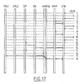
- the service item provider 64 (SIP-1) then checks the present time and obtains from the table therein the next available time point 0:10 as the starting time of the movie, distribution control data including the number "2" designating the SMU 20 storing the video and/or audio data if the movie and the number "2" designating one of the service item streams (SIS) from the SMU 20 making the movie available from the beginning at the time point 0:10, and the virtual channel number "21” for this stream, and supplies the SMU 20 designated by the end number "2” with the SIS number "2", virtual channel number "21” and the end device number "STB-2".
- SIS service item streams
- the service item provider 64 (SIP-1) up-dates the conversion table in the ATM switch 1 according to another table data available in the service item provider 64 (SIP-1) so that the relationship between input virtual channel number "21", for the service item stream (SIS) and the output virtual channel number "21" for the end device 40 (STB-2) is established. Therefore, the data stream of the requested movie is provided to the end device 40 (STB-2) from the beginning at time 0:10.
- the service item provider 64 obtains from the table therein distribution control data including the number "4" designating the SMU 20 having full VCR function capability and the number "1" designating one of the service item streams (SIS) from the SMU 20 designated by the number "4" with the SIS number "1", virtual channel number "28" and the end device number "STB-1".
- the service item provider 64 (SIP-1) up-dates the conversion table in the ATM switch 1 according to another table data available in the service item provider 64 (SIP-1) so that the relationship between input virtual channel number "28" for the service item stream (SIS) and the output virtual channel "7" for the end device 40 (STB-1) is established. Therefore, the data stream of the requested movie is provided to the end device 40 (STB-1) with full VCR function.
- Such an interactive communication system as outlined above is suitable to be used as a platform for a plurality of server-owners, navigation device owners, system manager owners and users simultaneously, where one party can for example exploit one or several SMU's 20, as well as a system manager 60 and/or one or several navigation devices 30.
- Fig. 1 the entire system is configured around a single ATM switch 1.
- Application of more than one private ATM switch and/or public ATM network is equally possible.
- another type of transmission network can be used.
- the network with one or more ATM switches is considered to be the most suitable network configuration for the applications envisaged.
- Fig. 2 shows a configuration of a SMU 20.
- Each SMU 20 contains a physical storage medium 21, for example an Magneto Optical (MO) disc and a corresponding driver or one or more hard discs and the corresponding drivers thereof, an ATM interface 29 as part of the SMU 20 or located outside such unit 20, and a controller 26 formed by a CPU 22, a RAM 24, a ROM 23, a memory 25, for example for storing a table, and a bus 27.
- a physical storage medium 21 for example an Magneto Optical (MO) disc and a corresponding driver or one or more hard discs and the corresponding drivers thereof
- an ATM interface 29 as part of the SMU 20 or located outside such unit 20
- a controller 26 formed by a CPU 22, a RAM 24, a ROM 23, a memory 25, for example for storing a table, and a bus 27.
- CPU 22 of controller 26 controls the storage medium 21 and other operations of the SMU 20 according to software programs stored in ROM 23 and an additional control software program downloaded into RAM 24 and table data stored in this memory of the SMU 20.
- the physical storage medium 21 primary contains service items, but can also contain control software program to be down-loaded to the end device 40 or one or more of the SMU's 20 when required.
- ROM 23 of the SMU 20 preferably contains a microkernel operating system and a storage medium interface resident software such as an ATM drive, an MO disc driver.
- the microkernel operating system functions as a basic set of instructions, capable only of the most elementary of communication operations, e.g. down-load of control software specifically tailored for subsequent communications to be performed by the SMU 20.
- the ATM driver is used for establishing communications through the ATM interface 29.
- the MO disc driver is responsible for the mode in which the physical storage medium 21 functions which will be described hereinafter.
- the controller 26 also contains a table 25, in which relationships between virtual channels and end devices 40 are established.
- the ATM interface 29 may communicate with the ATM switch 1 in a full duplex mode, where the ATM interface 29 can simultaneously handle incoming and outgoing ATM packets 28.
- Fig. 2 such an ATM packet 20 is shown to contain a header portion A, usually comprising five bytes, and an information field portion B, usually comprising forty-eight bytes.
- RAM 24 contains executable code in ROM 23, a down-loadable module for optimum functionality as a server, and a buffer.
- Fig. 3 shows a SMU 20, where bus 27 is divided into a separate control bus and a separate data bus to provide a high throughput.
- Fig. 4 shows a schematic representation of control and data flow in the SMU 20 shown in Fig. 3.
- incoming and outgoing video and/or audio data and incoming and outgoing control data and incoming control software program to be down-loaded.
- Respective packets of video and/or audio data, control data and software program even if these packets are transferred to same SMU 20 or same end device 40, should have different routing information in the header to be distinguishable from each other.
- Fig. 5 shows a third embodiment of the SMU 20, where an ATM switch 1 and the ATM interface 29 of the SMU 20 are incorporated.
- connections can be established from the SMU 20 directly through ATM interfaces 41 to the end devices 40.
- the system manager 60 may be connected to the ATM switch 1 or the controller 26 may replace the function of the system manager 60.
- Fig. 6 shows a SMU 20 corresponding to the embodiment of Fig. 2, where the method for reading and outputting data segments from a physical storage medium, e.g. a disc is shown.
- data groups are output via three virtual channels, which channels could also be formed by separate physical channels.
- the SMU 20 shown here contains a buffer 210 and a timer 211, where the buffer 210 is preferably a part of the ATM interface 29.
- the video data is divided in a predetermined number T of sentences, where T corresponds to the number of channels and equals three in case of Fig. 6.
- Each sentence is divided in a predetermined number N of data groups and N equals four in case of Fig. 6.
- the video data recorded in the above manner is sequentially and cyclically reproduced from the storage medium 21.
- the n-th data groups of the respective T sentences are sequentially stored in the buffer 210 and output to respective different virtual channels through the ATM interface 29.
- the virtual channels are switched over in the next and following cycles as shown in Fig. 7, so that N x T data groups are continuously reproduced via each virtual channel with a time difference of one sentence from each other as shown in the right hand side of Fig. 6.
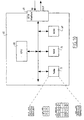
- Fig. 8 shows a configuration of a navigation device 30.
- Navigation device 30 preferably comprises: a controller 36, formed by a CPU 32, a ROM 33, a RAM 34 also for navigation software programs to be down-loaded to the end devices 40 and a bus 37; a table 35 for available video programs and identification data, for example a public address of available video programs, and also an ATM interface 31.
- the controller 36 controls operation of the navigation device 30 according to programs stored in ROM 33 and RAM 34.
- the navigation device 30 down-loads navigation software programs to the set top box 40, when the set top box 40 requires a navigation operation to the navigation device 30.
- the navigation device 30 then provides information relating to available video programs and identification data thereof to the set top box 40.
- Public addresses can be used when a public network is used in the interactive communication system.
- Many kinds and versions of the navigation menu can be provided, if the interactive communication system has a plurality of navigation devices 30, which handle for example a Japanese version, an English version, three dimensional graphical version etc.
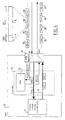
- Fig. 9 shows the configuration of an end device, here a set top box 40.
- the set top box 40 may comprise a CPU 45, a RAM 46, a ROM 47 and an MPEG decoder 48.
- CPU 45 controls operation of the set top box 40 according to programs stored in ROM 47 and RAM 46. Said programs may be down-loaded from the system manager 60, a SMU 20 or a navigation device 30.
- the MPEG decoder 48 decodes compressed video data and/or audio data, supplied via the ATM switch 1 and supplies video data, if necessary combined with data from a graphic processor 49 through a video RAM memory 50 to the monitor 43 and supplies audio data via an amplifier 51 to the speaker system 42.
- the CPU 45 produces demand data according to instruction data input through the keyboard 44 or a similar device by the user. Such demand data is output via the ATM interface 41.
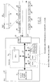
- Fig. 10 shows a configuration of the system manager 60.
- the system manager 60 contains a CPU 68, a ROM 69, a RAM 70, and here a memory for various VOD software programs to be down-loaded to the set top boxes 40 and/or the SMU's 20, an ATM interface 61 and memory 71, e.g. in the form of table means.
- the CPU 68 controls operation of the system manager 60.
- the system manager 60 provides operation software to SMU's 20 and set top boxes 40 and updates tables for data representing a relationship between input virtual channels and output virtual channels in the ATM switch 1.
- Such a system manager 60 can perform all functions described above relating to the storage medium manager 62, the program manager 67, the service item providers 64, the service item group 65 and the server routing manager 66.
- Fig. 11 shows a sequence of scenes, where said sequence can be accomplished by displaying video data on various transmission channels.
- Data groups are reproduced from a physical storage medium 21 containing the staggered recording data and output via these virtual channels in a similar manner to Fig. 6 and 7.
- the sequence of scenes can be altered by switching from channel to channel for input of video data comprising such a scene so that a simple VCR function can be realized. For example, by switching from channel 1 to channel 2 while the scene '2' is displayed, the scene '4' can be displayed, thereby skipping scene '3' as fast forward mode.
- Fig. 12 shows an example of a mosaic function to be performed by an end device 40, whereby selected scenes taken from a sequence are displayed on monitor 43.
- a user can in this way select a starting point, other than the beginning of a film, by issuing a corresponding demand through the input device 44.
- Such a mosaic function can of course also be used for visualizing a menu of service items selectable through one or several navigation devices 3, e.g. title frames of several selectable video programs, where such selected scenes for mosaic function can be displayed by switching the virtual channels on a real time basis and storing these into the video RAM 50 simultaneously or by reproducing the video data previously stored in the SMU 20 as mosaic video data.
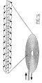
- recording formats of video data on a physical storage medium 21 will be explained, referring to figs. 13-15.
- a physical storage medium 21 is shown, where a head 90 is attached to an arm 91, movable to and from the center of the physical storage medium 21.
- the physical storage medium 21 is formed by a MO disc.
- Data tracks of the MO disc 21 contain data groups in the staggered recording sequence 92 shown in this Fig. 13 above the physical storage medium 21.
- the arrows above and beneath this representation of sequence 92 denote the order, in which head 90 reads the data groups from the physical storage medium 21.
- reproducing head 90 skips data groups on the outbound pass over the physical storage medium 21, where the skipped data groups are read during the inbound pass over the physical storage medium 21.
- Video data which is to be recorded in a storage medium with a format described above, is reproduced from said storage medium 21, and output from the SMU 20 to the ATM switch 1 through the ATM interface 29 as three virtual channels.
- first and second video data with the same content but opposite time lines are recorded on the disc.
- the data groups of the first video data and the data groups of the second video data are interleaved.
- the first video data is used, when the set top box requires normal forward, fast forward, or stepwise fast forward play mode.
- second video data is used when the set top box requires reverse play mode.
- the data groups of the first video data to be recorded on every other track of the disc.
- the data groups of the second video data are stored in remaining tracks of the disc. Then the recorded first video data is reproduced from every other track of the disc by moving a reproducing head in a first direction.
- Recorded second video data is reproduced from the remaining tracks of the disc by moving the reproducing head in this first direction. It is also possible to reproduce the second video data in the reverse if the first direction after the first video data are reproduced so that similar effects to the recording format shown in Fig. 13 is obtained.
- the second video data should be encoded in the reverse manner of the first video data. In such a case, it may not be possible to reproduce the second video data in the reverse direction as explained above.
- the forward data groups (1F, 2F, 3F, 4F etc.) are recorded in every fourth track in a similar manner to Fig. 13, while the reverse data groups (12R, 11R, 10R, 9R, etc.) are recorded before 2F, 3F, 4F etc. respectively, also in every fourth track.
- the distance of the head movement is minimized at the edges of the disc as will become clear from the sequences of 6F, 7F and 8F and 7R, 6R and 5R at the inside edge, and 12F, 1F and 2F, and 1R, 12R and 11R, respectively.
- Fig. 15 shows a diagram of a sequence of video data displayed on a monitor, where the sequence is obtained by using the recording format and reading sequence shown in Fig. 14, and by receiving from and sending to different virtual channels, respectively in order to obtain forward and/or reverse play modes, for which purpose data are recorded in the staggered fashion, described referring to Fig. 13, 14 and 14A as examples.
- the system manager 60 as shown in Fig. 1 also manages distribution of video data. If the system manager 60 receives a demand data from one or more of the end devices 40, even in the course of service, asking to provide a same video and/or audio data as transmitted from one of SMU 20 to or requested from other end devices 40, the system manager 60 outputs to the ATM switch 1 distribution control data including information of the input virtual channel of the selected video data from the SMU 20 and the output virtual channel of the end device 40 requesting the video and/or audio data which are generated in response to the received demand data.
- an end device STB-3 requests same video data "video 1", “video 2", and “video3" as requested by and transmitted to another end device STB-1 from the SMU 20 through an input virtual channel “vc 1" and an output virtual channel “vc7”
- the system manager 60 outputs the up-dated conversion table to the ATM switch 1, so that the header of the ATM packets transmitting "video 1", “video 2” and “video 3” are replaced in the ATM switch 1 with not only the header corresponding to an output virtual channel "vc7” but also the header corresponding an output virtual channel "vc8" designated by the end device STB-3. Therefore, the ATM packets containing "video 1", “video 2” and “video 3" are supplied to both of the end devices 40 STB-1 and STB-3 simultaneously.
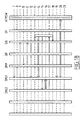
- the sequence of communication represents a method in which flow of video data from a SMU 20 to a set top box 40 is established.
- a user informs a set top box 40, denoted by STB, through his input device 44, that he wishes to gain access to the system.
- the set top box 40 replies by asking the user in step 2 what kind of service, like video-on-demand, games or just television, the user wishes to select. Such selectable options may be stored in memory of the set top box 40.
- step 3 the user enters his choice through his input device 44 to the set top box 40, which then involves the navigation device 30, in this figure denoted by Navi. Description below will relate to the case, where the user has selected a video-on-demand service menu, for which one or several navigation devices 30 are suitable. Nevertheless, only one navigation device 30 is represented in this figure for clarity.
- navigation device 30 provides set top box 40 with a menu of selectable video services, to which the navigation device 30 can gain access.
- menu options can also be included, referring the set top box 40 to another navigation device 30, which can gain access to other video services.
- set top box 40 passes the menu on to the user by display thereof on monitor 43.
- the user enters his choice through his input device 44, which in this case is a request for a further menu. This request is relayed to navigation device 30 in step 8, whereupon navigation device 30 supplies a new menu of selections to set top box 40 in step 9.
- Steps 7-10 can be repeated a number of times, until, as is the case in step 10, a menu displayed on monitor 43 by set top box 40 contains an option for a video program the user wishes to select, which is represented by step 11.
- Set top box 40 in step 12 requests service item provider 64, denoted by SIP, to provide for a video stream to a top set box with a given public address, corresponding to the address of the service item provider 64.
- service item provider 64 first request service item group 65, denoted by SIG, to provide set top box 40 with control data necessary for optimum handling by the set top box 40 of the video stream to be established, which control software is down-loaded into the set top box 40 in step 14.
- set top box 40 is capable of issuing commands relating to VCR functions, where in step 15 the first play command is issued to the service item provider 64.
- service item provider 64 locates the first available video stream for the request, which in this case originates from storage medium unit 40, denoted here by SMU1, and sets ATM switch 1, denoted by ATM SW to connect said storage medium unit 20 and set top box 40 by re-writing the virtual channel table in the ATM switch 1.
- the requested video stream is routed through ATM switch 1 to set top box 40, where the requested video program can now be displayed on monitor 43.
- Fig. 18 dynamic reconfiguration of the system is clarified.
- the service items group creates a new instance of a SMU installer and provides the number of the source SMU, of the destination SMU and other parameters.
- the SMU installer executes a download operation to SMU1 as destination and leaves SMU1 waiting for data.
- the SMU installer requests SMU2 as source to start providing data to SMU1 as destination.
- the requested data is transferred from SMU2 to SMU1.
- SMU2 reports to the SMU installer that the data transfer is completed.
- the SMU installer informs the SIG that SMU1 is ready to serve data, whereafter the SMU installer disappears.
- the SIG requests SMU1 to start serving data to a certain virtual channel, so that such data can be served to end users.
Claims (16)
- Informationsdaten-Dienstsystem für ein oder mehrere Endgeräte (40) eines oder mehrerer Benutzer, welches umfaßt:dadurch gekennzeichnet, daß jede Speicherträgereinheit (20) umfaßt:eine oder mehrere Speicherträgereinheiten (20) zum Speichern von Informationsdaten;eine Verwaltungseinrichtung (60) zum Verwalten der Verteilung der Informationsdaten für eines der Endgeräte, wobei die Verwaltungseinrichtung Bedarfsdaten empfängt, die sich auf Informationsdaten beziehen, die durch den Benutzer über sein Endgerät ausgewählt werden, und wobei die Verwaltungseinrichtung Verteilungssteuerdaten ausgibt, die die Kanalinformation der ausgewählten Informationsdaten und die Leitinformation für dieses Endgerät umfassen; undeine Leiteinrichtung (1) zum Verbinden der Speicherträgereinheit (-einheiten) mit dem Endgerät (Endgeräten) und zum Leiten der Informationsdaten von der Speicherträgereinheit (-einheiten) und der Verteilungssteuerdaten von der Verwaltungseinrichtung,einen Hauptspeicher (23) zum Speichern von Informationsdaten;eine Tabelleneinrichtung (25) zum Speichern von Daten, die eine Beziehung zwischen der Leitinformation und den Informationsdaten, die im Speicher gespeichert sind, zeigen;einen Programmspeicher (24) zum Speichern von Programmdaten zum Steuern des Betriebs der Speicherträgereinheit;einer Steuereinrichtung (22) zum Steuern des Hauptspeichers, der Tabelleneinrichtung und der Programmspeichereinrichtung gemäß Programmdaten und zum Ausgeben eines oder mehrere Steuersignale zum Endgerät (Endgeräten); undzumindest eine Schnittstelle (29) zum Übertragen der Informationsdaten mit der Leitinformation und einem Steuersignal in der Form von einem oder mehreren Paketen zur Leiteinrichtung und zum Empfangen von Programmdaten für den Betrieb der Speicherträgereinheit in der Form von einem oder mehreren Paketen von der Leiteinrichtung, wobei die Programmdaten für den Betrieb der Speicherträgereinheit in die Programmspeichereinrichtung über die Schnittstelle heruntergeladen werden.
- Informationsdienstleistersystem nach Anspruch 1, wobei die Leiteinrichtung zumindest einen ATM-Schalter umfaßt.
- Informationsdienstleistersystem nach Anspruch 1 oder 2, wobei die Informationsdaten Video- und/oder Audiodaten sind.
- Informationsdienstleistersystem nach Anspruch 1, 2 oder 3, wobei die Anforderungsdaten eine öffentliche Adresse umfassen, die den ausgewählten Informationsdaten zugewiesen ist.
- Informationsdienstleistersystem nach einem der Ansprüche 1 bis 4, welches mit der Steuereinrichtung zum Steuern der Speicherträgereinheit gemäß den Verteilungssteuerdaten versehen ist, so daß die Speicherträgereinheit die ausgewählten Informationsdaten, die die Leitinformation umfassen, an die Leiteinrichtung ausgibt.
- Informationsdienstleistersystem nach einem der Ansprüche 1 bis 5, wobei die Verwaltungseinrichtung Programmdaten für den Betrieb einer optischen Anzeige von Informationsdaten und/oder Audioinformation über die Lautsprechereinrichtung von der Speicherträgereinheit auf das Endgerät liefert.
- Informationsdienstleistersystem nach einem der Ansprüche 1 bis 6, wobei die Verwaltungseinrichtung Programmdaten für die Informationszurückgewinnung für das Endgerät zur Verfügung stellt.
- Informationsdienstleistersystem nach Anspruch 3, wobei die Informationszurückgewinnung Video-auf-Anforderung umfaßt.
- Informationsdienstleistersystem nach einem der Ansprüche 1 bis 8, welches umfaßt:
zumindest eine zweite Speicherträgereinheit zum Speichern von zweiten Informationsdaten, die mit der Leiteinrichtung verbunden ist, wobei die Verwaltungseinrichtung eine Tabelle zum Speichern von Daten umfaßt, die eine Informationsdatenzuordnung für die erste und zweite Speicherträgereinheit zeigen, und wobei die Verwaltungseinrichtung Verteilungssteuerdaten für entweder die erste oder die zweite Speicherträgereinheit (-einheiten) auf der Basis von Bedarfsdaten von einem Endgerät zur Verfügung stellt. - Informationsdienstleistersystem nach einem der Ansprüche 1 bis 9, wobei die Leitinformation sich auf einen oder mehrere virtuelle Kanäle bezieht und die Schnittstelle eine ATM-Schnittstelle ist.
- Informationsdienstleistersystem nach Anspruch 9 oder 10, wobei die Schnittstelle Steuerdaten empfängt, die einen ausgewählten Betriebsmodus für das Endgerät zeigen und wobei die Steuereinrichtung die Speichereinrichtung gemäß den empfangenen Steuerdaten steuert, so daß die Informationsdaten von der Speichereinrichtung in dem ausgewählten Betriebsmodus reproduziert werden.
- Informationsdienstleistersystem nach Anspruch 11, wobei der Betriebsmodus einen Standbildmodus, einen schnellen Vorlaufmodus, einen Umkehrmodus und/oder einen Mosaikmodus umfaßt.
- Informationsdienstleistersystem nach Anspruch 3 oder gemäß einem der Ansprüche 4 - 12, wenn abhängig von Anspruch 3, wobei die Video- und/oder Audiodaten in eine vorherbestimmte Anzahl von Datengruppen unterteilt sind, wobei die vorherbestimmte Anzahl von Datengruppen in einer Sequenz, die sich von der ursprünglichen Sequenz unterscheidet, auf einem Aufzeichnungsträger in der Speicherträgereinheit (den Speicherträgereinheiten) aufgezeichnet ist, und wobei die Leiteinrichtung fortlaufende Video- und/oder Audiodaten zum Endgerät (zu den Endgeräten) liefert, wobei die Datengruppen von einer oder mehrerer Speicherträgereinheiten auf ein oder mehrere Endgeräte geschaltet werden.
- Informationsdienstleistersystem nach Anspruch 13, wobei der Aufzeichnungsträger eine schnelle Platte ist und wobei ein erster Bereich der Datengruppe auf jeder N-ten Spur der Platte aufgezeichnet ist, wobei N = 1, 2, 3 ... , und die verbleibenden Bereiche der Datengruppen auf verbleibenden Spuren der Platte aufgezeichnet sind.
- Informationsdienstleistersystem nach Anspruch 14, wobei der erste Bereich der Datengruppen durch Bewegen eines Kopfs in einer ersten Richtung reproduziert wird und der verbleibende Bereich der Datengruppen durch Bewegen des Kopfes in einer zweiten Richtung entgegengesetzt zur ersten Richtung reproduziert wird.
- Informationsdienstleistersystem nach Anspruch 3 oder nach einem der Ansprüche 4 bis 15, wenn vom Patentanspruch 3 abhängig, wobei die Video- und/oder Audiodaten in eine vorherbestimmte Anzahl von Datengruppen unterteilt sind, und die Video- und /oder Audiodaten in T Sätze, wobei T = 2, 3, 4, ..., in Abhängigkeit von der Anzahl von Kanälen unterteilt sind, wobei die vorherbestimmte Anzahl von Datengruppen in der Speicherträgereinheit (den Speicherträgereinheiten) in einer so geänderten Reihenfolge aufgezeichnet ist, daß die N-ten Datengruppe des letzten Satzes der Videodaten nach der N-ten Datengruppe des ersten Satzes erscheint, wobei N = 1, 2, 3, 4, ..., und wobei die Leiteinrichtung einen stetigen Strom von Videodaten zum Endgerät (zu den Endgeräten) durch Umschalten der Datengruppen von der Speicherträgereinheit (den Speicherträgereinheiten) zwischen virtuellen Kanälen liefert.
Priority Applications (11)
| Application Number | Priority Date | Filing Date | Title |
|---|---|---|---|
| AT95200819T ATE194448T1 (de) | 1995-03-31 | 1995-03-31 | System für information auf anfrage |
| EP95200819A EP0735763B1 (de) | 1995-03-31 | 1995-03-31 | System für Information auf Anfrage |
| DE69517795T DE69517795T2 (de) | 1995-03-31 | 1995-03-31 | System für Information auf Anfrage |
| TW084111669A TW307078B (de) | 1995-03-31 | 1995-11-03 | |
| PCT/EP1996/001412 WO1996031057A1 (en) | 1995-03-31 | 1996-03-28 | A system for information on demand |
| AU54984/96A AU5498496A (en) | 1995-03-31 | 1996-03-28 | A system for information on demand |
| US11/481,391 USRE42905E1 (en) | 1995-03-31 | 1996-03-28 | System for information on demand |
| CA002216282A CA2216282A1 (en) | 1995-03-31 | 1996-03-28 | A system for information on demand |
| KR1019970707029A KR19980703630A (ko) | 1995-03-31 | 1996-03-28 | 정보 서버 시스템 |
| JP8528952A JPH11509993A (ja) | 1995-03-31 | 1996-03-28 | インフォメーションオンディマンドシステム |
| US08/930,472 US6760917B2 (en) | 1995-03-31 | 1996-03-28 | System for information on demand |
Applications Claiming Priority (1)
| Application Number | Priority Date | Filing Date | Title |
|---|---|---|---|
| EP95200819A EP0735763B1 (de) | 1995-03-31 | 1995-03-31 | System für Information auf Anfrage |
Publications (2)
| Publication Number | Publication Date |
|---|---|
| EP0735763A1 EP0735763A1 (de) | 1996-10-02 |
| EP0735763B1 true EP0735763B1 (de) | 2000-07-05 |
Family
ID=8220153
Family Applications (1)
| Application Number | Title | Priority Date | Filing Date |
|---|---|---|---|
| EP95200819A Expired - Lifetime EP0735763B1 (de) | 1995-03-31 | 1995-03-31 | System für Information auf Anfrage |
Country Status (10)
| Country | Link |
|---|---|
| US (2) | USRE42905E1 (de) |
| EP (1) | EP0735763B1 (de) |
| JP (1) | JPH11509993A (de) |
| KR (1) | KR19980703630A (de) |
| AT (1) | ATE194448T1 (de) |
| AU (1) | AU5498496A (de) |
| CA (1) | CA2216282A1 (de) |
| DE (1) | DE69517795T2 (de) |
| TW (1) | TW307078B (de) |
| WO (1) | WO1996031057A1 (de) |
Families Citing this family (22)
| Publication number | Priority date | Publication date | Assignee | Title |
|---|---|---|---|---|
| DE69638296D1 (de) | 1996-11-27 | 2011-01-05 | Sony Europ Belgium Nv | Vorrichtung zur Abgabe von Daten mit Mustererkennung |
| DE69834792T2 (de) * | 1997-10-17 | 2007-05-16 | Sony Corp. | Datenverteilungssystem, Verteilungseinrichtung, Terminaleinrichtung und Datenverteilungsverfahren |
| JP3861413B2 (ja) | 1997-11-05 | 2006-12-20 | ソニー株式会社 | 情報配信システム、情報処理端末装置、携帯端末装置 |
| AU5138100A (en) * | 1999-05-18 | 2000-12-18 | Bridge Information Systems, Inc. | Multi-level broadband multimedia delivery system |
| US7809849B2 (en) * | 1999-10-13 | 2010-10-05 | Starz Entertainment, Llc | Pre-storing multiple programs with user control of playback |
| US8806549B1 (en) | 1999-10-13 | 2014-08-12 | Starz Entertainment, Llc | Pre-storing a portion of a program to allow user control of playback |
| WO2001048645A1 (fr) * | 1999-12-28 | 2001-07-05 | Sony Corporation | Dispositif et procede de traitement de donnees numeriques |
| US20020129048A1 (en) * | 2000-03-03 | 2002-09-12 | Surgient Networks, Inc. | Systems and methods for resource monitoring in information storage environments |
| JP2003044387A (ja) * | 2001-05-18 | 2003-02-14 | Sharp Corp | データサーバ装置、データ配信プログラム、データ配信プログラムを記録したコンピュータ読み取り可能な記録媒体およびクライアント装置 |
| US7299486B1 (en) * | 2001-12-04 | 2007-11-20 | Unisys Corporation | Control program, for a supervisor processor in a video-on-demand system, which builds subgroups of internet protocol headers and transmission control lists |
| US7299487B1 (en) * | 2001-12-04 | 2007-11-20 | Unisys Corporation | Control program, for a co-processor in a video-on-demand system, which uses transmission control lists to send video data packets with respective subgroups of internet protocol headers |
| US7287268B1 (en) * | 2001-12-04 | 2007-10-23 | Unisys Corporation | Video-on-demand system which builds transmission control lists and uses such lists to send video data packets with respective subgroups of internet protocol headers |
| US20030217369A1 (en) * | 2002-05-17 | 2003-11-20 | Heredia Edwin Arturo | Flexible application information formulation |
| JP3841169B2 (ja) * | 2002-08-21 | 2006-11-01 | ソニー株式会社 | 通信システム、データ処理装置およびデータ処理方法、並びにプログラム |
| CN1711790A (zh) * | 2002-11-06 | 2005-12-21 | 皇家飞利浦电子股份有限公司 | 在移动设备上显示信息项 |
| WO2004107749A1 (en) * | 2003-05-29 | 2004-12-09 | Eat.Tv, Llc | System for presentation of multimedia content |
| US20050138655A1 (en) * | 2003-12-22 | 2005-06-23 | Randy Zimler | Methods, systems and storage medium for managing digital rights of segmented content |
| US20050177618A1 (en) * | 2003-12-22 | 2005-08-11 | Randy Zimler | Methods, systems and storage medium for managing bandwidth of segmented content |
| JP4890459B2 (ja) * | 2004-10-29 | 2012-03-07 | イーエイティー.ティーブイ、インコーポレイテッド | ビデオベースインタラクティブアプリケーションを可能にするためのシステム |
| WO2006103578A1 (en) * | 2005-03-29 | 2006-10-05 | Koninklijke Philips Electronics N.V. | Method and device for providing multiple video pictures |
| JP4347322B2 (ja) * | 2006-07-14 | 2009-10-21 | ソニー株式会社 | 受信装置および方法、並びにプログラム |
| GB2501145A (en) * | 2012-04-12 | 2013-10-16 | Supercell Oy | Rendering and modifying objects on a graphical user interface |
Family Cites Families (53)
| Publication number | Priority date | Publication date | Assignee | Title |
|---|---|---|---|---|
| US4141066A (en) | 1977-09-13 | 1979-02-20 | Honeywell Inc. | Process control system with backup process controller |
| US4707781A (en) | 1979-01-09 | 1987-11-17 | Chopp Computer Corp. | Shared memory computer method and apparatus |
| US4463380A (en) | 1981-09-25 | 1984-07-31 | Vought Corporation | Image processing system |
| US4604687A (en) * | 1983-08-11 | 1986-08-05 | Lucasfilm Ltd. | Method and system for storing and retrieving multiple channel sampled data |
| JP3004018B2 (ja) * | 1987-12-15 | 2000-01-31 | 株式会社東芝 | 信号記録装置 |
| JP2685783B2 (ja) * | 1988-03-09 | 1997-12-03 | 株式会社東芝 | 誤り制御方式 |
| US4949187A (en) | 1988-12-16 | 1990-08-14 | Cohen Jason M | Video communications system having a remotely controlled central source of video and audio data |
| US5047857A (en) | 1989-04-20 | 1991-09-10 | Thomson Consumer Electronics, Inc. | Television system with zoom capability for at least one inset picture |
| US5497502A (en) | 1989-06-07 | 1996-03-05 | Genese | Method and apparatus for transmitting information recorded on digital disks from a central server to subscribers via a high data rate digital telecommunications network |
| GB2248322B (en) | 1990-09-25 | 1994-04-06 | Sony Broadcast & Communication | Memory apparatus |
| JP3107822B2 (ja) * | 1991-01-31 | 2000-11-13 | 富士通株式会社 | コネクションレス通信方式 |
| JP2938611B2 (ja) | 1991-05-14 | 1999-08-23 | 富士通株式会社 | テレビ信号交換方式 |
| DE69232164T2 (de) | 1991-08-22 | 2002-07-18 | Sun Microsystems Inc | Netzwerkvideoanbietergerät und-verfahren |
| US5341474A (en) | 1992-05-15 | 1994-08-23 | Bell Communications Research, Inc. | Communications architecture and buffer for distributing information services |
| US5371532A (en) | 1992-05-15 | 1994-12-06 | Bell Communications Research, Inc. | Communications architecture and method for distributing information services |
| US5291554A (en) | 1992-05-28 | 1994-03-01 | Tv Answer, Inc. | Shared-price custom video rentals via interactive TV |
| US5623344A (en) | 1992-09-01 | 1997-04-22 | Hitachi America, Ltd. | Digital video recording device with trick play capability |
| US5373288A (en) | 1992-10-23 | 1994-12-13 | At&T Corp. | Initializing terminals in a signal distribution system |
| US5371551A (en) * | 1992-10-29 | 1994-12-06 | Logan; James | Time delayed digital video system using concurrent recording and playback |
| EP0598516A3 (de) | 1992-11-05 | 1996-07-03 | Sony Corp | Aufzeichnung und Wiedergabe von bewegten Bildern. |
| US5504883A (en) * | 1993-02-01 | 1996-04-02 | Lsc, Inc. | Method and apparatus for insuring recovery of file control information for secondary storage systems |
| US5365041A (en) | 1993-04-26 | 1994-11-15 | Robotron Corporation | Induction heating coil for bonding metal sheets |
| US5539449A (en) * | 1993-05-03 | 1996-07-23 | At&T Corp. | Integrated television services system |
| EP0625857B1 (de) * | 1993-05-19 | 1998-06-24 | ALCATEL BELL Naamloze Vennootschap | Videoserver |
| EP0625855A1 (de) | 1993-05-19 | 1994-11-23 | ALCATEL BELL Naamloze Vennootschap | Netzwerk für die Schaltung von Videodiensten |
| DE69317267T2 (de) | 1993-05-19 | 1998-06-25 | Alsthom Cge Alcatel | Netzwerk für Video auf Anfrage |
| DE69319329T2 (de) * | 1993-05-19 | 1998-10-29 | Alsthom Cge Alcatel | Verfahren zur Speicherverwaltung eines Videoservers |
| US5621456A (en) | 1993-06-22 | 1997-04-15 | Apple Computer, Inc. | Methods and apparatus for audio-visual interface for the display of multiple program categories |
| CA2127347A1 (en) * | 1993-07-07 | 1995-01-08 | Donald F. Hooper | Segmented video on-demand system |
| US5442390A (en) | 1993-07-07 | 1995-08-15 | Digital Equipment Corporation | Video on demand with memory accessing and or like functions |
| US5541738A (en) | 1994-04-12 | 1996-07-30 | E. Guide, Inc. | Electronic program guide |
| JP3038668B2 (ja) * | 1993-09-20 | 2000-05-08 | 富士通株式会社 | ビデオ情報配信システム |
| US5610841A (en) | 1993-09-30 | 1997-03-11 | Matsushita Electric Industrial Co., Ltd. | Video server |
| US5689641A (en) * | 1993-10-01 | 1997-11-18 | Vicor, Inc. | Multimedia collaboration system arrangement for routing compressed AV signal through a participant site without decompressing the AV signal |
| US5991502A (en) | 1993-10-04 | 1999-11-23 | Matsushita Electric Industrial Co., Ltd. | Optical recording device which calculates distances between I-frames and records I-frame addresses in a sector |
| US5544327A (en) | 1994-03-01 | 1996-08-06 | International Business Machines Corporation | Load balancing in video-on-demand servers by allocating buffer to streams with successively larger buffer requirements until the buffer requirements of a stream can not be satisfied |
| US5521841A (en) | 1994-03-31 | 1996-05-28 | Siemens Corporate Research, Inc. | Browsing contents of a given video sequence |
| US5532735A (en) * | 1994-04-29 | 1996-07-02 | At&T Corp. | Method of advertisement selection for interactive service |
| US5734589A (en) * | 1995-01-31 | 1998-03-31 | Bell Atlantic Network Services, Inc. | Digital entertainment terminal with channel mapping |
| US5606359A (en) | 1994-06-30 | 1997-02-25 | Hewlett-Packard Company | Video on demand system with multiple data sources configured to provide vcr-like services |
| CN1122087A (zh) * | 1994-07-21 | 1996-05-08 | 株式会社日立制作所 | 图像信息分配系统 |
| US5603058A (en) | 1994-09-08 | 1997-02-11 | International Business Machines Corporation | Video optimized media streamer having communication nodes received digital data from storage node and transmitted said data to adapters for generating isochronous digital data streams |
| US5530557A (en) * | 1994-09-12 | 1996-06-25 | International Business Machines Corporation | Online placement of video files determined by a function of the bandwidth to space ratio of each of the storage devices in a server environment |
| US5740075A (en) | 1994-09-12 | 1998-04-14 | Bell Atlantic Network Services, Inc. | Access subnetwork controller for video dial tone networks |
| US5594789A (en) | 1994-10-13 | 1997-01-14 | Bell Atlantic Network Services, Inc. | Transaction implementation in video dial tone network |
| US5512934A (en) * | 1994-12-29 | 1996-04-30 | At&T Corp. | System and method for transmission of programming on demand |
| US5557320A (en) | 1995-01-31 | 1996-09-17 | Krebs; Mark | Video mail delivery system |
| US5619247A (en) | 1995-02-24 | 1997-04-08 | Smart Vcr Limited Partnership | Stored program pay-per-play |
| ATE220275T1 (de) | 1995-03-31 | 2002-07-15 | Sony Service Ct Europe Nv | Informationsdienstsystem mit archiv- und abgabespeichereinheit |
| US5561791A (en) | 1995-04-10 | 1996-10-01 | Digital Equipment Corporation | Method and apparatus for conditioning timed program independent of transport timing |
| US5790173A (en) * | 1995-07-20 | 1998-08-04 | Bell Atlantic Network Services, Inc. | Advanced intelligent network having digital entertainment terminal or the like interacting with integrated service control point |
| GB9515336D0 (en) | 1995-07-26 | 1995-09-20 | Int Computers Ltd | Multi-media services system |
| US5812526A (en) * | 1995-12-21 | 1998-09-22 | Industrial Technology Research Institute | Traffic control mechanism in ATM communications network |
-
1995
- 1995-03-31 AT AT95200819T patent/ATE194448T1/de not_active IP Right Cessation
- 1995-03-31 EP EP95200819A patent/EP0735763B1/de not_active Expired - Lifetime
- 1995-03-31 DE DE69517795T patent/DE69517795T2/de not_active Expired - Lifetime
- 1995-11-03 TW TW084111669A patent/TW307078B/zh not_active IP Right Cessation
-
1996
- 1996-03-28 AU AU54984/96A patent/AU5498496A/en not_active Abandoned
- 1996-03-28 JP JP8528952A patent/JPH11509993A/ja active Pending
- 1996-03-28 KR KR1019970707029A patent/KR19980703630A/ko not_active Application Discontinuation
- 1996-03-28 US US11/481,391 patent/USRE42905E1/en not_active Expired - Fee Related
- 1996-03-28 CA CA002216282A patent/CA2216282A1/en not_active Abandoned
- 1996-03-28 WO PCT/EP1996/001412 patent/WO1996031057A1/en not_active Application Discontinuation
- 1996-03-28 US US08/930,472 patent/US6760917B2/en not_active Ceased
Also Published As
| Publication number | Publication date |
|---|---|
| US6760917B2 (en) | 2004-07-06 |
| JPH11509993A (ja) | 1999-08-31 |
| KR19980703630A (ko) | 1998-12-05 |
| EP0735763A1 (de) | 1996-10-02 |
| TW307078B (de) | 1997-06-01 |
| CA2216282A1 (en) | 1996-10-03 |
| USRE42905E1 (en) | 2011-11-08 |
| US20030110505A1 (en) | 2003-06-12 |
| AU5498496A (en) | 1996-10-16 |
| ATE194448T1 (de) | 2000-07-15 |
| DE69517795T2 (de) | 2000-12-28 |
| DE69517795D1 (de) | 2000-08-10 |
| WO1996031057A1 (en) | 1996-10-03 |
Similar Documents
| Publication | Publication Date | Title |
|---|---|---|
| EP0735763B1 (de) | System für Information auf Anfrage | |
| EP0735765B1 (de) | Speichereinheit | |
| EP0735538B1 (de) | Speichereinheit mit versetzter Aufzeichnung | |
| EP0735766B1 (de) | Videodienstsystem mit der Funktion eines Videokassettenrekorders | |
| EP0735762B1 (de) | Speichereinheit zur Aufzeichnung von Informationsdaten vorzugsweise von Video- und/oder Audiodaten | |
| EP0735759B1 (de) | System für Information auf Anfrage mit Mehrfachübertragung | |
| EP0735760B1 (de) | Informationsdienstsystem mit Archiv- und Abgabespeichereinheit | |
| EP0735761B1 (de) | Navigationssystem | |
| EP0735758B1 (de) | Informationsdienstsystem mit Speichermedienverwaltung | |
| EP0735764B1 (de) | Verfahren für Information-auf-Anfrage mit entsprechender Steuervorrichtung |
Legal Events
| Date | Code | Title | Description |
|---|---|---|---|
| PUAI | Public reference made under article 153(3) epc to a published international application that has entered the european phase |
Free format text: ORIGINAL CODE: 0009012 |
|
| AK | Designated contracting states |
Kind code of ref document: A1 Designated state(s): AT BE CH DE DK ES FR GB GR IE IT LI LU MC NL PT SE |
|
| 17P | Request for examination filed |
Effective date: 19961016 |
|
| RAP1 | Party data changed (applicant data changed or rights of an application transferred) |
Owner name: SONY EUROPA B.V. |
|
| 17Q | First examination report despatched |
Effective date: 19980827 |
|
| GRAG | Despatch of communication of intention to grant |
Free format text: ORIGINAL CODE: EPIDOS AGRA |
|
| GRAG | Despatch of communication of intention to grant |
Free format text: ORIGINAL CODE: EPIDOS AGRA |
|
| GRAH | Despatch of communication of intention to grant a patent |
Free format text: ORIGINAL CODE: EPIDOS IGRA |
|
| GRAH | Despatch of communication of intention to grant a patent |
Free format text: ORIGINAL CODE: EPIDOS IGRA |
|
| GRAA | (expected) grant |
Free format text: ORIGINAL CODE: 0009210 |
|
| AK | Designated contracting states |
Kind code of ref document: B1 Designated state(s): AT BE CH DE DK ES FR GB GR IE IT LI LU MC NL PT SE |
|
| PG25 | Lapsed in a contracting state [announced via postgrant information from national office to epo] |
Ref country code: NL Free format text: LAPSE BECAUSE OF FAILURE TO SUBMIT A TRANSLATION OF THE DESCRIPTION OR TO PAY THE FEE WITHIN THE PRESCRIBED TIME-LIMIT Effective date: 20000705 Ref country code: LI Free format text: LAPSE BECAUSE OF FAILURE TO SUBMIT A TRANSLATION OF THE DESCRIPTION OR TO PAY THE FEE WITHIN THE PRESCRIBED TIME-LIMIT Effective date: 20000705 Ref country code: IT Free format text: LAPSE BECAUSE OF FAILURE TO SUBMIT A TRANSLATION OF THE DESCRIPTION OR TO PAY THE FEE WITHIN THE PRESCRIBED TIME-LIMIT;WARNING: LAPSES OF ITALIAN PATENTS WITH EFFECTIVE DATE BEFORE 2007 MAY HAVE OCCURRED AT ANY TIME BEFORE 2007. THE CORRECT EFFECTIVE DATE MAY BE DIFFERENT FROM THE ONE RECORDED. Effective date: 20000705 Ref country code: GR Free format text: LAPSE BECAUSE OF NON-PAYMENT OF DUE FEES Effective date: 20000705 Ref country code: ES Free format text: THE PATENT HAS BEEN ANNULLED BY A DECISION OF A NATIONAL AUTHORITY Effective date: 20000705 Ref country code: CH Free format text: LAPSE BECAUSE OF FAILURE TO SUBMIT A TRANSLATION OF THE DESCRIPTION OR TO PAY THE FEE WITHIN THE PRESCRIBED TIME-LIMIT Effective date: 20000705 Ref country code: BE Free format text: LAPSE BECAUSE OF FAILURE TO SUBMIT A TRANSLATION OF THE DESCRIPTION OR TO PAY THE FEE WITHIN THE PRESCRIBED TIME-LIMIT Effective date: 20000705 Ref country code: AT Free format text: LAPSE BECAUSE OF FAILURE TO SUBMIT A TRANSLATION OF THE DESCRIPTION OR TO PAY THE FEE WITHIN THE PRESCRIBED TIME-LIMIT Effective date: 20000705 |
|
| REF | Corresponds to: |
Ref document number: 194448 Country of ref document: AT Date of ref document: 20000715 Kind code of ref document: T |
|
| REG | Reference to a national code |
Ref country code: CH Ref legal event code: EP |
|
| REG | Reference to a national code |
Ref country code: IE Ref legal event code: FG4D |
|
| REF | Corresponds to: |
Ref document number: 69517795 Country of ref document: DE Date of ref document: 20000810 |
|
| PG25 | Lapsed in a contracting state [announced via postgrant information from national office to epo] |
Ref country code: SE Free format text: LAPSE BECAUSE OF FAILURE TO SUBMIT A TRANSLATION OF THE DESCRIPTION OR TO PAY THE FEE WITHIN THE PRESCRIBED TIME-LIMIT Effective date: 20001005 Ref country code: DK Free format text: LAPSE BECAUSE OF FAILURE TO SUBMIT A TRANSLATION OF THE DESCRIPTION OR TO PAY THE FEE WITHIN THE PRESCRIBED TIME-LIMIT Effective date: 20001005 |
|
| PG25 | Lapsed in a contracting state [announced via postgrant information from national office to epo] |
Ref country code: PT Free format text: LAPSE BECAUSE OF FAILURE TO SUBMIT A TRANSLATION OF THE DESCRIPTION OR TO PAY THE FEE WITHIN THE PRESCRIBED TIME-LIMIT Effective date: 20001006 |
|
| ET | Fr: translation filed | ||
| NLV1 | Nl: lapsed or annulled due to failure to fulfill the requirements of art. 29p and 29m of the patents act | ||
| REG | Reference to a national code |
Ref country code: CH Ref legal event code: PL |
|
| PG25 | Lapsed in a contracting state [announced via postgrant information from national office to epo] |
Ref country code: MC Free format text: LAPSE BECAUSE OF NON-PAYMENT OF DUE FEES Effective date: 20010331 Ref country code: LU Free format text: LAPSE BECAUSE OF NON-PAYMENT OF DUE FEES Effective date: 20010331 |
|
| PG25 | Lapsed in a contracting state [announced via postgrant information from national office to epo] |
Ref country code: IE Free format text: LAPSE BECAUSE OF NON-PAYMENT OF DUE FEES Effective date: 20010402 |
|
| PLBE | No opposition filed within time limit |
Free format text: ORIGINAL CODE: 0009261 |
|
| STAA | Information on the status of an ep patent application or granted ep patent |
Free format text: STATUS: NO OPPOSITION FILED WITHIN TIME LIMIT |
|
| 26N | No opposition filed | ||
| RAP2 | Party data changed (patent owner data changed or rights of a patent transferred) |
Owner name: SONY SERVICE CENTER (EUROPE) N.V. |
|
| REG | Reference to a national code |
Ref country code: GB Ref legal event code: IF02 |
|
| REG | Reference to a national code |
Ref country code: IE Ref legal event code: MM4A |
|
| PGFP | Annual fee paid to national office [announced via postgrant information from national office to epo] |
Ref country code: DE Payment date: 20140328 Year of fee payment: 20 |
|
| PGFP | Annual fee paid to national office [announced via postgrant information from national office to epo] |
Ref country code: FR Payment date: 20140319 Year of fee payment: 20 |
|
| PGFP | Annual fee paid to national office [announced via postgrant information from national office to epo] |
Ref country code: GB Payment date: 20140319 Year of fee payment: 20 |
|
| REG | Reference to a national code |
Ref country code: DE Ref legal event code: R071 Ref document number: 69517795 Country of ref document: DE |
|
| REG | Reference to a national code |
Ref country code: GB Ref legal event code: PE20 Expiry date: 20150330 |
|
| PG25 | Lapsed in a contracting state [announced via postgrant information from national office to epo] |
Ref country code: GB Free format text: LAPSE BECAUSE OF EXPIRATION OF PROTECTION Effective date: 20150330 |