EP0735650B2 - Electric motor - Google Patents
Electric motor Download PDFInfo
- Publication number
- EP0735650B2 EP0735650B2 EP96104701A EP96104701A EP0735650B2 EP 0735650 B2 EP0735650 B2 EP 0735650B2 EP 96104701 A EP96104701 A EP 96104701A EP 96104701 A EP96104701 A EP 96104701A EP 0735650 B2 EP0735650 B2 EP 0735650B2
- Authority
- EP
- European Patent Office
- Prior art keywords
- housing
- frequency converter
- housing part
- electric motor
- motor according
- Prior art date
- Legal status (The legal status is an assumption and is not a legal conclusion. Google has not performed a legal analysis and makes no representation as to the accuracy of the status listed.)
- Expired - Lifetime
Links
Images

Classifications
-
- H—ELECTRICITY
- H02—GENERATION; CONVERSION OR DISTRIBUTION OF ELECTRIC POWER
- H02K—DYNAMO-ELECTRIC MACHINES
- H02K11/00—Structural association of dynamo-electric machines with electric components or with devices for shielding, monitoring or protection
- H02K11/30—Structural association with control circuits or drive circuits
- H02K11/33—Drive circuits, e.g. power electronics
-
- H—ELECTRICITY
- H02—GENERATION; CONVERSION OR DISTRIBUTION OF ELECTRIC POWER
- H02K—DYNAMO-ELECTRIC MACHINES
- H02K2213/00—Specific aspects, not otherwise provided for and not covered by codes H02K2201/00 - H02K2211/00
- H02K2213/12—Machines characterised by the modularity of some components
-
- H—ELECTRICITY
- H02—GENERATION; CONVERSION OR DISTRIBUTION OF ELECTRIC POWER
- H02K—DYNAMO-ELECTRIC MACHINES
- H02K5/00—Casings; Enclosures; Supports
- H02K5/04—Casings or enclosures characterised by the shape, form or construction thereof
- H02K5/22—Auxiliary parts of casings not covered by groups H02K5/06-H02K5/20, e.g. shaped to form connection boxes or terminal boxes
- H02K5/225—Terminal boxes or connection arrangements
Description
Die Erfindung betrifft einen frequenzumrichtergespeisten Elektromotor mit den im Oberbegriff des Anspruches 1 angegebenen Merkmalen.The invention relates to a frequency converter supplied electric motor with the features specified in the preamble of claim 1.
Frequenzumrichtergespeiste Elektromotoren der eingangs erwähnten Art werden heutzutage vermehrt insbesondere zum Antrieb von Strömungsarbeitsmaschinen, wie z. B. Kreiselpumpen und Gebläsen eingesetzt. Gerade bei derartigen Maschinen kann durch Varianz der Drehzahl, insbesondere durch das bei Frequenzumrichterspeisung mögliche Anheben der Drehzahl das Leistungsfeld bei günstigen Wirkungsgraden nach oben hin erweitert werden, da ihre Leistung mit der dritten Potenz der Antriebsdrehzahl steigt. Andererseits kann die durch die Frequenzumrichterspeisung mögliche Drehzahlvarianz auch im Teillastbereich Vorteile bringen, da bei entsprechender Regelung die der erforderlichen Leistung entsprechende Drehzahl eingestellt werden kann, so daß das Aggregat mit angepaßtem Energieaufwand arbeitet.Frequency converter fed electric motors of the type mentioned are now increasingly used in particular for the drive of fluid flow machines, such. B. centrifugal pumps and blowers used. Especially in such machines can be extended by variance of the speed, in particular by the possible in Frequenzumrichterspeisung raising the speed of the power field at low efficiencies upwards, since their power increases with the third power of the drive speed. On the other hand, the speed variance possible by the frequency converter feeding can also bring advantages in the partial load range, since with appropriate control, the speed corresponding to the required power can be adjusted, so that the unit operates with adapted energy expenditure.
Zum Antrieb solcher Aggregate sind sogenannte Normmotoren bekannt, die von namhaften Pumpenherstellern angeboten werden. Es handelt sich dabei um Motorbaureihen, die hinsichtlich ihrer Leistung so abgestuft sind, daß sich für jeden Anwendungsfall ein passender Antriebsmotor finden läßt.To drive such units so-called standard motors are known, which are offered by well-known pump manufacturers. These are engine series, which are graded in terms of their performance so that can find a suitable drive motor for each application.
Insbesondere bei Motoren höherer Leistung benötigt auch der Frequenzumrichter einen erheblichen Raumbedarf. Zum einen benötigen die Kondensatoren des Leistungskreises des Frequenzumrichters mit zunehmender Motorleistung mehr Raum, zum anderen wird die Abfuhr der im Leistungkreis des Frequenzumrichters erzeugten Verlustwärme mit wachsender Motorleistung problematischer.Especially with higher power motors and the frequency converter requires a considerable amount of space. On the one hand, the capacitors of the power circuit of the frequency converter require more space with increasing motor power, on the other hand, the dissipation of the heat generated in the power circuit of the frequency converter with increasing motor power problematic.
Es ist bekannt, den Frequenzumrichter seitlich am Motorgehäuse nach Art eines Klemmenkastens anzuflanschen und durch Konvektionskühlung oder aber durch den Kühlluftstrom des Motors zu kühlen. Doch dies ist bei Motoren größerer Leistung ebenfalls kritisch, da zum einen die Kühlung des Frequenzumrichters Probleme bereitet und zum anderen die räumlichen Abmessungen des Frequenzumrichters den Einsatz des Elektromotors beschränken.It is known to flare the frequency converter laterally on the motor housing in the manner of a terminal box and to cool by convection cooling or by the cooling air flow of the engine. However, this is also critical for larger power engines, as the cooling of the frequency converter causes problems and the spatial dimensions of the frequency converter limit the use of the electric motor.
Aus EP-A1-0 619 432, von der die Erfindung ausgeht, ist ein gattungsgemäßer frequenzumrichtergespeister Elektromotor bekannt. Bei diesem Motor ist der Frequenzumrichter nicht seitlich, sondern rückseitig, also in Verlängerung des Motorengehäuses angebracht, wobei das Frequenzumrichtergehäuse über einen als Lüfterhaube ausgebildeten Gehäuseteil an das Motorgehäuseteil anschließt, derart, daß der vom Motorlüfter erzeugte Luftstrom zunächst im wesentlichen radial anströmt, um dann nach Durchtritt durch das Lüfterrad längs der Kühlrippen des Motors zu strömen. In dem Einströmbereich, in dem der Luftstrom im wesentlichen radial gerichtet ist, überstreicht dieser einen Kühlkörper, der Teil des Frequenzumrichtergehäuses ist.From EP-A1-0 619 432, from which the invention proceeds, a generic frequenzumrichtergespeister electric motor is known. In this engine, the frequency converter is not laterally, but the back, so mounted in extension of the motor housing, the frequency converter housing connected via a designed as a fan cover housing part to the motor housing part, such that the air flow generated by the motor fan initially flows substantially radially, then to Passage through the fan along the cooling fins of the engine to flow. In the inflow region, in which the air flow is directed substantially radially, this passes over a heat sink, which is part of the frequency converter housing.
Aufgrund der ausschließlich radialen Luftführung im Bereich des Kühlkörpers ist die Kühlwirkung dieser bekannten Konstruktion sehr begrenzt, da die Strecke, über welche die anströmende Luft Wärme des Frequenzumrichters aufnehmen kann, vergleichsweise kurz ist. Darüber hinaus haben diese ausschließlich innen liegenden Kühlrippen den Nachteil, daß eine Konvektionskühlung nach außen aufgrund der räumlichen Anordnung der Kühlrippen praktisch nicht möglich ist.Due to the exclusively radial air flow in the region of the heat sink, the cooling effect of this known construction is very limited, since the distance over which the incoming air can absorb heat of the frequency converter is comparatively short. In addition, these exclusively internal cooling fins have the disadvantage that a convection cooling to the outside due to the spatial arrangement of the cooling fins is practically impossible.
Aus US-4,668,898 ist ein frequenzumrichtergespeister Elektromotor mit einem Kühlluftgebläse bekannt, bei dem der Frequenzumrichter in einem berippten Gehäuse rückseitig des Motors angeordnet ist, so daß eine wirksame Kühlung des Frequenzumrichters auch in Bereichen außerhalb des Kühlluftstromes durch Konvektionskühlung erfolgen kann. Nachteilig hierbei ist jedoch, daß das gesamte Frequenzumrichtergehäuse der Kühlung dient und insoweit konstruktiv gebunden ist.From US-4,668,898 a frequency converter fed electric motor with a cooling air blower is known, in which the frequency converter is arranged in a ribbed housing on the back side of the motor, so that an effective cooling of the frequency converter can also take place in areas outside of the cooling air flow by convection cooling. The disadvantage here, however, is that the entire frequency converter housing is used for cooling and is structurally bound.
Vor diesem Stand der Technik liegt der Erfindung die Aufgabe zugrunde, unter Vermeidung der vorgeschilderten Nachteile ein gattungsgemäßes Aggregat so auszubilden, daß einerseits eine intensive Kühlung des Frequenzumrichtergehäuses erreicht und andererseits das Frequenzumrichtergehäuse in weiten Bereichen frei gestaltbar ist. Darüber hinaus soll eine kompakte und die Verlustwärme des Frequenzumrichters gut abführende Konstruktion geschaffen werden, die einfach und kostengünstig in der Herstellung ist.Before this state of the art, the invention has the object, while avoiding the described disadvantages of a generic unit in such a way that on the one hand achieves intensive cooling of the frequency converter housing and on the other hand, the frequency converter housing is freely designable in many areas. In addition, a compact and the heat loss of the frequency converter good laxative construction should be created, which is simple and inexpensive to manufacture.
Diese Aufgabe wird gemäß der Erfindung mit den Merkmalen des Anspruchs 1 gelöst.This object is achieved according to the invention with the features of claim 1.
Die erfindungsgemäße Lösung sieht vor, daß der Frequenzumrichter in Flucht zum übrigen Motorgehäuse angeordnet ist und der Kühlluftstrom des Motors gezielt auch zur Kühlung des Frequenzumrichters ausgenutzt wird. Dabei ist das Frequenzumrichtergehäuse so ausgebildet, daß ein Gehäuseteil zugleich die Lüfterhaube des Motors bildet. Auf diese Weise kann ein und dasselbe Motorgehäuse wahlweise mit Frequenzumrichter oder aber auch nur mit der üblichen Lüfterhaube, also ohne Frequenzumrichter ohne konstruktive Änderungen bereitgestellt werden. Die Integration des Motorlüfters in das Frequenzumrichtergehäuse hat zudem den Vorteil, daß durch entsprechende Strömungsführung innerhalb des Frequenzumrichtergehäuses eine gezielte Wärmeabfuhr durch den gesamten Kühlluftstrom des Motors erfolgen kann. Des weiteren läßt sich eine sehr kompakte Bauweise realisieren, da auch der sonst nicht genutzte Raum im Bereich der Lüfterhaube für Bauteile bzw. Kühlteile des Frequenzumrichters nutzbar ist. Der so gebildete frequenzumrichtergespeiste Elektromotor ist kompakt und schlank im Aufbau, so daß in der Mehrzahl der Anwendungsfälle die durch den Frequenzumrichter bedingte Vergrößerung der Bauform keine Probleme bereitet. Gemäß der Erfindung ist das erste Gehäuseteil des Frequenzumrichtergehäuses mit einer Querwand versehen und diese Querwand zum wärmeleitenden Anschluß der wärmeerzeugenden Bauteile des Leistungskreises vorgesehen und ausgebildet. Deshalb kann nämlich die Wärmeankopplung unabhängig von der Baugröße des Frequenzumrichters über einen entsprechenden Heatspreader an dieser Planfläche erfolgen, so daß eine gute Wärmeableitung erzielt wird. Denn dieses erste Teil ist das Gehäuseteil, in dem der Kühlluftstrom zwangsgeführt ist, d. h., das intensiv von Kühlluft durchströmt wird. Die weiteren Gehäuseteile des Frequenzumrichters brauchen daher hinsichtlich der Wärmeabfuhr nicht besonders ausgebildet zu werden. Um die Wärmeabfuhr dieses ersten Gehäuseteiles weiter zu verbessern, sind sowohl innen als auch außen eine Vielzahl von Kühlrippen vorgesehen, wobei im Fußbereich der äußeren Kühlrippen Durchbrüche vorgesehen sind, durch welche der Kühlluftstrom zum Lüfterrad hin eintritt. Hierdurch wird die Kühlung des Frequenzumrichters bei vergleichsweise kleiner Baugröße noch weiter intensiviert. Das erste Gehäuseteil des Frequenzumrichters ist im Bereich seiner Querwand an die Topographie der Leistungselektronik einerseits und der Außenkontur des Lüfterrades andererseits angepaßt, was sowohl einer gezielten Wärmeabfuhr als auch einer kompakten Bauform dient. An dieses erste Gehäuseteil schließt sich dann ein weiteres Gehäuseteil an, das ausschließlich Gehäusefunktion haben kann und daher konstruktiv weitgehend frei gestaltbar ist.The solution according to the invention provides that the frequency converter is arranged in alignment with the rest of the motor housing and the cooling air flow of the motor is specifically exploited for cooling the frequency converter. The frequency converter housing is designed so that a housing part at the same time forms the fan cowl of the engine. In this way, one and the same motor housing can be provided either with frequency converter or only with the usual fan cover, so without frequency converter without design changes. The integration of the motor fan in the frequency converter housing also has the advantage that targeted flow of heat through the entire cooling air flow of the engine can be carried out by appropriate flow control within the frequency converter housing. Furthermore, a very compact design can be realized, as well as the otherwise unused space in the fan hood for components or cooling parts of the frequency converter is available. The frequency converter-fed electric motor thus formed is compact and slim in construction, so that in the majority of applications, the increase in the design caused by the frequency converter causes no problems. According to the invention, the first housing part of the frequency converter housing is provided with a transverse wall and this transverse wall for heat-conducting connection of the heat-generating Components of the power circuit provided and designed. Therefore, namely, the heat coupling regardless of the size of the frequency converter via a corresponding Heatspreader done on this plane surface, so that a good heat dissipation is achieved. For this first part is the housing part in which the cooling air flow is forcibly guided, that is, which is intensively flowed through by cooling air. The other housing parts of the frequency therefore need not be specially designed in terms of heat dissipation. In order to further improve the heat dissipation of this first housing part, a plurality of cooling fins are provided both inside and outside, wherein openings are provided in the foot region of the outer cooling fins through which the cooling air flow enters the fan wheel. As a result, the cooling of the frequency converter is intensified even with a comparatively small size. The first housing part of the frequency converter is adapted in the region of its transverse wall to the topography of the power electronics on the one hand and the outer contour of the fan wheel on the other hand, which serves both a targeted heat dissipation and a compact design. At this first housing part, then joins another housing part, which may have only housing function and therefore structurally largely freely designable.
Bevorzugt ist das Frequenzumrichtergehäuse modular aufgebaut, so daß für eine Motorbaureihe gleichen Außenquerschnittes das erste wärmeleitende Gehäuseteil des Frequenzumrichters stets unverändert und lediglich das weitere durch ein rohrförmiges Hohlprofil gebildete Gehäuseteil variiert wird. Diese Varianz erfolgt ausschließlich in der Länge, d. h., die Anpassung des Frequenzumrichtergehäuses an die jeweilige Motorgröße erfolgt, indem dieses rohrförmige Hohlprofil in entsprechender Länge angesetzt wird. Der dieses Hohlprofil endseitig abschließende Deckel kann ebenfalls bei allen Ausführungen gleich bleiben.Preferably, the frequency converter housing is modular, so that for a motor series same outer cross-section, the first thermally conductive housing part of the frequency always unchanged and only the further formed by a tubular hollow profile housing part is varied. This variance occurs exclusively in length, d. h., the adaptation of the frequency converter housing to the respective motor size is carried out by this tubular hollow profile is set in the appropriate length. The end of this hollow profile end cap can also remain the same in all versions.
Insbesondere für Motoren kleiner Baugröße kann es zweckmäßig sein, das erste und das weitere Gehäuseteil des Frequenzumrichtergehäuses einstückig, beispielsweise als Gußteil auszubilden.In particular, for motors of small size, it may be expedient, the first and the further housing part of the frequency converter housing in one piece, for example, form as a casting.
Das Frequenzumrichtergehäuse kann ohne Probleme spritzwassergeschützt oder auch hermetisch abgeschlossen sein, indem beispielsweise zwischen dem ersten Gehäuseteil und dem Profilgehäuseteil sowie zwischen dem Profilgehäuseteil und dem Deckel entsprechende Dichtungsmittel vorgesehen sind. Es versteht sich, daß auch die Kabeldurch- bzw. -herausführungen im Frequenzumrichtergehäuse entsprechend geschützt ausgebildet sind.The frequency converter housing can splash-proof or hermetically be completed without problems by, for example, between the first housing part and the profile housing part and between the profile housing part and the lid corresponding sealing means are provided. It is understood that the cable through or -herausführungen are designed protected in the frequency converter housing.
Fertigungstechnisch besonders günstig ist es, das erste Gehäuseteil als metallisches Gußteil auszubilden, das gut wärmeleitfähig ist und das weitere Gehäuseteil als Rohrabschnitt eines entsprechenden Metallprofilrohres.Manufacturing technology is particularly favorable to form the first housing part as a metallic casting, which is highly thermally conductive and the other housing part as a pipe section of a corresponding metal profile tube.
Die elektrische Leitungsverbindung zwischen dem am Motorgehäuse vorgesehenen Klemmenkasten und dem Frequenzumrichter kann vorteilhaft durch ein an der Außenseite des Motorgehäuses angeordnetes Rohr erfolgen, das einerseits im Klemmenkasten und andererseits im Frequenzumrichtergehäuse mündet. Die im Rohr befindlichen elektrischen Leitungen liegen dort geschützt und gut zugänglich. Und auch diese Ausbildung ermöglicht den Anschluß desselben Motors sowohl über den Klemmenkasten direkt an das elektrische Versorgungsnetz oder aber über den Klemmenkasten an den Frequenzumrichter und von dort an das elektrische Versorgungsnetz je nach Ausstattung des Motors.The electrical line connection between the terminal box provided on the motor housing and the frequency converter can advantageously be effected by a pipe arranged on the outside of the motor housing, which opens on the one hand in the terminal box and on the other hand in the frequency converter housing. The electrical cables in the pipe are protected there and easily accessible. And this training allows the connection of the same motor both via the terminal box directly to the electrical supply network or via the terminal box to the frequency converter and from there to the electrical supply network depending on the equipment of the engine.
Wenn der Elektromotor im Querschnitt eine etwa rechteckige Außenkontur aufweist, wie dies bei modernen Motoren dieser Art üblich ist, dann wird dieses Rohr vorzugsweise im Eckbereich angeordnet, da dieser Raum für den eigentlichen Motor ohnehin nicht nutzbar ist und der Lüfterflügel diesen Bereich nicht überstreicht.If the electric motor in cross-section has an approximately rectangular outer contour, as is customary in modern engines of this type, then this pipe is preferably arranged in the corner, since this space for the actual engine is not usable anyway and the fan blade does not sweep this area.
Der endseitige Deckel des Frequenzumrichtergehäuses dient lediglich zum Abschluß des aus einem Rohrabschnitt gebildeten Gehäuseteiles und hat somit keine tragende Funktion. Der Deckel kann daher vorzugsweise als kostengünstiges Kunststoffspritzgußteil ausgebildet sein und unabhängig von der Länge des Frequenzumrichtergehäuses endseitig angebracht werden.The end cover of the frequency converter housing is only used to terminate the housing part formed from a pipe section and thus has no supporting function. The lid may therefore be preferably formed as a low-cost plastic injection molded part and be attached end regardless of the length of the frequency converter housing.
Das Frequenzumrichtergehäuse ist dabei fluchtend zum Motorgehäuse angeordnet und verläuft in dessen Querschnittsaußenkontur, so daß die Baugröße quer zur Motorachse durch den Frequenzumrichter nicht beeinflußt wird. Gerade diese Baugröße ist jedoch bei der Mehrzahl der Anwendungsfälle von Bedeutung.The frequency converter housing is arranged in alignment with the motor housing and extends in its cross-sectional outer contour, so that the size is not influenced transversely to the motor axis by the frequency converter. However, this size is important in the majority of applications.
Die Erfindung ist nachfolgend eines in der Zeichnung dargestellten Ausführungsbeispieles näher erläutert. Es zeigen:
- Fig. 1
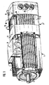
- in schematischer perspektivischer Darstellung eine Ansicht eines Elektromotors nach der Erfindung,
- Fig. 2
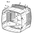
- in vergrößerter Darstellung das erste Gehäuseteil des Frequenzumrichters in Darstellung entsprechend Fig. 1,
- Fig. 3
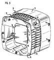
- das erste Gehäuseteil in Darstellung nach Fig. 2, jedoch von der anderen Seite und
- Fig. 4
- einen Längsschnitt durch Motor und Frequenzumrichter.
- Fig. 1
- in a schematic perspective view of a view of an electric motor according to the invention,
- Fig. 2
- in an enlarged view, the first housing part of the frequency converter in representation corresponding to FIG. 1,
- Fig. 3
- the first housing part in representation of FIG. 2, but from the other side and
- Fig. 4
- a longitudinal section through the motor and frequency converter.
Der anhand der Figuren 1 und 4 in seiner Gesamtheit dargestellte Elektromotor weist ein Motorgehäuse 1 und ein dazu in Richtung der Motorachse fluchtend angeordnetes Frequenzumrichtergehäuse 2 auf. Zu einer Stirnseite des Motorgehäuses 1 tritt die Antriebswelle 3 des Motors aus diesem aus, zur anderen Stirnseite sitzt auf dieser Welle 3 ein Lüfterrad 4. Die Welle 3 ist in an sich bekannter Weise zu beiden Seiten des Motorgehäuses 1 gelagert und trägt einen Rotor 5, der innerhalb eines Stators 6 umläuft.The electric motor shown in its entirety with reference to FIGS. 1 and 4 has a motor housing 1 and a frequency converter housing 2 arranged in alignment with it in the direction of the motor axis. To a front side of the motor housing 1, the
Das metallische Motorgehäuse 1 ist an seiner Außenseite mit in Richtung der Motorachse verlaufenden Kühlrippen 7 versehen, derart, daß sich eine im Querschnitt etwa rechteckige jedoch abgerundete Außenkontur ergibt. An der Oberseite des Motors ist ein die Kühlrippen 7 unterbrechender und das eigentliche Motorgehäuse nach oben hin überragender Klemmenkasten 8 angeordnet, in den die Statorwicklungsanschlüsse geführt sind und über den der elektrische Anschluß des Motors erfolgt.The metallic motor housing 1 is provided on its outside with extending in the direction of the motor axis cooling fins 7, such that there is a cross-sectionally approximately rectangular but rounded outer contour. At the top of the motor is a cooling fins 7 interrupting and the actual motor housing upwardly superior
Das Motorgehäuse 1 kann in an sich bekannter Weise durch eine Lüfterhaube abgeschlossen werden, dann erfolgt der elektrische Anschluß direkt im Klemmenkasten 8. Bei der anhand der Figuren dargestellten Ausführungsform ist der Motor jedoch mit einem Frequenzumrichter versehen, ein entsprechendes Frequenzumrichtergehäuse 2 schließt sich an das Motorgehäuse 1 an.The motor housing 1 can be completed in a conventional manner by a fan cover, then the electrical connection is made directly in the
Das Frequenzumrichtergehäuse 2 besteht aus einem ersten Gehäuseteil 9, das sich direkt an das Motorgehäuse 1 anschließt, dieses seitlich übergreift und gleichzeitig die Lüfterhaube bildet, sowie einem zweiten Gehäuseteil 10 und einem Deckel 11. Das zweite Gehäuseteil 10 ist durch einen Abschnitt eines entsprechend ausgebildeten Profilstranges eines Aluminiumhohlprofiles gebildet und bestimmt die Länge des Frequenzumrichtergehäuses 2. Das erste Gehäuseteil 9 ist als metallisches Spritzgußteil ausgebildet, der Deckel 11 ist ein Kunststoffspritzteil.The frequency converter housing 2 consists of a first housing part 9, which connects directly to the motor housing 1, this laterally engages and at the same time forms the fan guard, and a
Das erste Gehäuseteil 9 weist einen rohrförmigen, das Motorgehäuse 1 übergreifenden Teil 12 auf, an den sich ein berippter Teil 13 anschließt. Der rohrförmige Teil 12 weist seitliche Bohrungen 14 auf, an denen das erste Gehäuseteil 9 mittels Schrauben am Motorgehäuse 1 befestigt ist. Der berippte Teil 13 des ersten Gehäuseteiles 9 weist äußere Kühlrippen 15 auf, die im wesentlichen zu den Kühlrippen 7 des Motorgehäuses 1 fluchten. Zwischen den Kühlrippen 15 sind in dem Bereich, wo der berippte Teil 13 in den rohrförmigen Teil 12 übergeht, Durchbrüche in der Gehäusewand vorgesehen, so daß der vom Lüfterrad angesaugte Kühlluftstrom längs dieser Kühlrippen 15 in das Frequenzumrichtergehäuse 2 einströmen kann.The first housing part 9 has a tubular, the motor housing 1
Innerhalb des ersten Gehäuseteiles 9 ist eine Querwand 16 vorgesehen, welche das Frequenzumrichtergehäuse 2 vom Lüfterraum abschließt. Diese Querwand 16 ist abgestuft ausgebildet, wie aus Fig. 2 ersichtlich ist. Auf diese Weise können auch innerhalb des ersten Gehäuseteiles 9 noch weitere Kühlrippen vorgesehen werden, insbesondere wird die innere Oberfläche des Frequenzumrichtergehäuses vergrößert, was zu einem noch intensiveren Wärmeaustausch mit dem Kühlluftstrom führt und zudem eine räumliche Anpassung an die Bauteile des Leistungskreises des Frequenzumrichters ermöglicht, wie dies anhand von Fig. 4 sichtbar ist. Diese abgestuft ausgebildete Querwand 16 ist an der zum zweiten Gehäuseteil 10 weisenden Seite als Planfläche 17 zum Wärmeanschluß der Leistungselektronik ausgebildet. Der daneben liegende, zum Motor hin abfallende Bereich ist ausgebildet zur Aufnahme der Kondensatoren 18 des Leistungkreises sowie einer Spule 19 des Frequenzumrichters. Der wärmeleitende Anschluß an die Planfläche 17 erfolgt in an sich bekannter Weise über einen Heatspreader, der seinerseits wärmeleitend mit dem wärmeerzeugenden Halbleiterbauelementen des Leistungskreises des Frequenzzumrichters verbunden ist.Within the first housing part 9, a
In Fig. 4 ist eine Platine 20 sichtbar, welche die wesentlichen Bauteile des Leistungskreises trägt. Es ist deutlich sichtbar, daß das erste Gehäuseteil 9 insbesondere innerhalb des berippten Teiles 13 zur Aufnahme dieser sich von der Platine 20 erhebenden Bauteile vorgesehen und ausgebildet ist (siehe Fig. 3).In Fig. 4, a
Jenseits der Platine 20 schließt sich im Bereich des zweiten Gehäuseteiles 10 eine Isolierplatte 21 an sowie eine Platine 22, die weitere elektronische Bauteile des Frequenzumrichters trägt.On the other side of the
Bei Vorschaltung eines Frequenzumrichters erfolgt der Anschluß des Motors nicht direkt über den Klemmenkasten, sondern über den Frequenzumrichter. Die elektrische Leitungsverbindung zwischen Klemmenkasten 8 und Frequenzumrichtergehäuse 2 erfolgt über ein Rohr 23, das auf der zum Frequenzumrichtergehäuse 2 weisenden Seite des Klemmenkastens 8 anschließt, den rohrförmigen Teil 12 des ersten Gehäuseteiles 9 durchsetzt, an den Kühlrippen 15 vorbeiläuft und schließlich in einem Flansch 24 am Ende des berippten Teiles 13 des ersten Gehäuseteiles 9 in das zweite Gehäuseteil 10 mündet. Das Rohr 23 ist an seinen Enden dicht mit dem Frequenzumrichtergehäuse 2 einerseits und dem Klemmenkasten 8 andererseits verbunden, so daß sowohl der Klemmenkasten 8 als auch das Frequenzumrichtergehäuse 2 hermetisch abgeschlossen, zumindest jedoch spritzwassergeschützt ausgebildet sein können.When connecting a frequency converter, the motor is not connected directly via the terminal box, but via the frequency inverter. The electrical line connection between
In dem zweiten Gehäuseteil 10 sind drei mit Gewinde versehenen Bohrungen vorgesehen, in denen aus Kunststoff bestehende Leitungsdurchführungen 25 eingeschraubt sind. Mittels dieser Leitungsdurchführungen 25 werden die elektrischen Anschlußleitungen aus dem Frequenzumrichtergehäuse 2 dicht herausgeführt.In the
Das zweite als Rohrabschnitt ausgebildete Gehäuseteil 10 ist über den Flansch 24 des ersten Gehäuseteiles 9, darin vorgesehene Bohrungen und entsprechende Befestigungsschrauben mit diesem befestigt. Entsprechend ist der Deckel 11 zur anderen Seite mittels Schrauben befestigt.The second formed as a pipe
In einer Baureihe sind Motorengehäuse 1 unterschiedlicher Länge vorgesehen, die jedoch die gleichen Querschnittsanschlußmaße aufweisen. In gewissen Grenzen kann also die Leistung des Motors allein durch Änderung der Baulänge (bei entsprechender Anpassung des inneren Aufbaues) verändert werden. Eine entsprechende Leistungsanpassung des Frequenzumrichters ist jedoch notwendig. Mit zunehmender Motorleistung wächst insbesondere die Größe der Kondensatoren 18, die im Frequenzumrichtergehäuse unterzubringen sind. Als Längenausgleich dient hier das zweite Gehäuseteil 10, das entsprechend der erforderlichen Baulänge angelängt wird. Auf diese Weise kann das Frequenzumrichtergehäuse 2 in der Länge variiert werden, ohne in sonstiger Weise konstruktiv verändert zu werden. Es genügt also für eine Motorbaureihe gleicher Außenkontur, das Frequenzumrichtergehäuse 2 hinsichtlich des zweiten Gehäuseteiles 10 anzupassen. Die in der Herstellung aufwendigen Spritzgußteile, nämlich das erste Gehäuseteil 9 und auch der Deckel 11 bleiben unverändert. Da das zweite Gehäuseteil 10 aus einem Profilrohrabschnitt besteht, kann es in beliebiger Länge kostengünstig bereitgestellt werden.In a series engine housing 1 of different lengths are provided, however, have the same cross-sectional connection dimensions. Within certain limits, so the performance of the engine alone by changing the length (with appropriate adjustment of the internal structure) can be changed. An appropriate power adjustment of the frequency converter is necessary. As the motor power increases, the size of the
- 1 -1 -
- Motorgehäusemotor housing
- 2 -2 -
- FrequenzumrichtergehäuseAC drive
- 3 -3 -
- Antriebswelledrive shaft
- 4 -4 -
- Lüfterradfan
- 5 -5 -
- Rotorrotor
- 6 -6 -
- Statorstator
- 7 -7 -
- Kühlrippen des MotorsCooling ribs of the engine
- 8 -8th -
- Klemmenkastenterminal box
- 9 -9 -
- erstes Gehäuseteilfirst housing part
- 10 -10 -
- zweites Gehäuseteilsecond housing part
- 11 -11 -
- Deckelcover
- 12 -12 -
- rohrförmiger Teil von 9tubular part of 9
- 13 -13 -
- berippter Teil von 9Nipped part of 9
- 14 -14 -
- Bohrungendrilling
- 15 -15 -
- Kühlrippen des FrequenzumrichtersCooling fins of the frequency converter
- 16 -16 -
- Querwandpartition
- 17 -17 -
- Planflächeplane surface
- 18 -18 -
- Kondensatorencapacitors
- 19 -19 -
- SpuleKitchen sink
- 20 -20 -
- Platinecircuit board
- 21 -21 -
- Isolierplatteinsulation
- 22 -22 -
- Platinecircuit board
- 23 -23 -
- Rohrpipe
- 24 -24 -
- Flanschflange
- 25 -25 -
- LeitungsdurchführungenCable bushings
Claims (8)
- A frequency-converter-fed electric motor with a cooling air blower (4) whose cooling air flow for cooling the motor is guided along cooling ribs (7) arranged on the motor housing (1), with which the frequency converter is arranged in a frequency converter housing (2) which is releasably connected to the motor housing (1) and which comprises a first heat-conducting housing part (9) and at least one further housing part (10), wherein the first housing part (9) of the frequency converter housing (2) forms the fan cowl and comprises a transverse wall (16) which is provided and designed for the heat-conducting connection (17) of the heat-producing components of the power circuit of the frequency converter, and the further housing part (10) at one end connects to the first housing part (9), wherein the first housing part (9) is formed ribbed characterised in that in the foot region of the cooling ribs (15) there are provided openings in the housing wall as air entry openings for the cooling air flow and that the first housing part (9) of the frequency converter in the region of its transverse wall (16) on the one hand is adapted to the topography of the power electronics and on the other hand to the outer contour of the fanwheel (4).
- An electric motor according to claim 1, characterised in that the further housing part (10) of the frequency converter housing (2) is formed by a tubular hollow profile which at its free end is terminated by a lid (11).
- An electric motor according to one of the preceding claims, characterised in that the first and the further housing part are formed as one-piece.
- An electric motor according to one of the preceding claims, characterised in that the frequency converter housing (2) is terminated in a splashproof manner.
- An electric motor according to one of the preceding claims, characterised in that the first housing part (9) is a metallic cast part and the further housing part (10) connecting thereto is a metal tube section.
- An electric motor according to one of the preceding claims, characterised in that the terminal box (8) is arranged on the outer side of the motor housing (1) and is connected via at least one outer-lying tube (23) to the frequency converter housing (2), through which electrical leads are guided.
- An electric motor according to one of the preceding claims, characterised in that the end-side lid (11) of the frequency converter housing (2) is a plastic injection moulded part.
- An electric motor according to one of the preceding claims, characterised in that the frequency converter housing (2) is aligned to the motor housing and essentially runs into its cross sectional outer contour.
Applications Claiming Priority (2)
| Application Number | Priority Date | Filing Date | Title |
|---|---|---|---|
| DE19511114A DE19511114C1 (en) | 1995-03-25 | 1995-03-25 | Electric motor |
| DE19511114 | 1995-03-25 |
Publications (3)
| Publication Number | Publication Date |
|---|---|
| EP0735650A1 EP0735650A1 (en) | 1996-10-02 |
| EP0735650B1 EP0735650B1 (en) | 1999-08-18 |
| EP0735650B2 true EP0735650B2 (en) | 2007-05-30 |
Family
ID=7757816
Family Applications (1)
| Application Number | Title | Priority Date | Filing Date |
|---|---|---|---|
| EP96104701A Expired - Lifetime EP0735650B2 (en) | 1995-03-25 | 1996-03-25 | Electric motor |
Country Status (3)
| Country | Link |
|---|---|
| US (1) | US5714816A (en) |
| EP (1) | EP0735650B2 (en) |
| DE (2) | DE19511114C1 (en) |
Families Citing this family (71)
| Publication number | Priority date | Publication date | Assignee | Title |
|---|---|---|---|---|
| EP0896855B1 (en) * | 1993-10-12 | 2003-02-26 | SMC Kabushiki Kaisha | Actuator |
| JPH0984294A (en) * | 1995-09-19 | 1997-03-28 | Mitsubishi Electric Corp | Variable speed motor |
| DE19622396A1 (en) * | 1996-06-04 | 1997-12-18 | Alexander Dr Stoev | Frequency converter for a drive device |
| DE19726258C2 (en) * | 1996-07-01 | 2001-10-04 | Barmag Barmer Maschf | Godet unit for guiding and conveying a thread |
| FR2753848B1 (en) * | 1996-09-26 | 1998-12-11 | ELECTRIC MOTOR WITH INTEGRATED ELECTRONIC CONTROL | |
| DE29700643U1 (en) * | 1997-01-15 | 1997-03-13 | Siemens Ag | Cooling concept for an electric drive system |
| DE19704226B4 (en) * | 1997-02-05 | 2004-09-30 | Sew-Eurodrive Gmbh & Co. Kg | Klemmdeckelumrichter |
| DE19714784A1 (en) * | 1997-04-10 | 1998-10-22 | Danfoss As | Compact drive |
| DE19723781A1 (en) * | 1997-06-06 | 1998-12-10 | Abb Daimler Benz Transp | Converter-powered drive system |
| US6949849B1 (en) | 1998-06-30 | 2005-09-27 | General Electric Company | Motor endshield assembly for an electronically commutated motor |
| KR100604509B1 (en) * | 1998-06-30 | 2006-07-24 | 제너럴 일렉트릭 캄파니 | Motor endshield assembly for an electronically commutated motor |
| DE19843771A1 (en) * | 1998-09-24 | 2000-03-30 | Mannesmann Vdo Ag | Electromotive actuator, in particular with a throttle valve |
| DE19843990C1 (en) * | 1998-09-25 | 1999-08-19 | Dienes Apparatebau Gmbh | Heated godet roller assembly for processing synthetic filaments and yarns |
| ES2152852B1 (en) * | 1998-10-06 | 2001-10-01 | Tecnotrans Sabre S A | COMPACT MOTOR-VARIATOR-REDUCER SET FOR DRIVING INDUSTRIAL MACHINES. |
| DE19851439A1 (en) * | 1998-11-09 | 2000-03-30 | Daimler Chrysler Ag | Electrical machine with die cast housing, has stator subjected to liquid coolant, with integrated cooling channels in stator and recesses on outer periphery |
| DE19859930A1 (en) * | 1998-12-24 | 2000-06-29 | Dietz Motoren Gmbh & Co Kg | Electric motor arrangement with rotor rotating about motor axis in motor housing with electronic control unit esp. frequency changer designed so that control unit is arranged displaced in direction of motor axis |
| DE29908962U1 (en) * | 1999-05-21 | 1999-09-02 | Neumag Gmbh | Winding machine |
| DE19945823C1 (en) * | 1999-09-24 | 2000-10-26 | Neumag Gmbh | Spooling machine for continuously fed chord(s) has electronic unit mounted beneath cantilever bearer arm so that air flow generated by rotating spool can be used to cool electronic unit |
| DE10010961A1 (en) * | 2000-03-06 | 2001-09-20 | Grundfos As | Motor assembly for a submersible pump unit |
| US7679234B1 (en) * | 2000-09-22 | 2010-03-16 | Isothermal Systems Research, Inc. | Spray cool means for cooling a modular inverter electric motor system |
| DE10063321A1 (en) * | 2000-12-19 | 2002-06-20 | Gfas Mbh Ges Fuer Aufladetechn | Electrically driven flow compressor |
| US6398521B1 (en) | 2001-01-30 | 2002-06-04 | Sta-Rite Industries, Inc. | Adapter for motor and fluid pump |
| US6589018B2 (en) | 2001-08-14 | 2003-07-08 | Lakewood Engineering And Manufacturing Co. | Electric fan motor assembly with motor housing control switch and electrical input socket |
| US6926502B2 (en) * | 2002-02-22 | 2005-08-09 | A. O. Smith Corporation | Combination shield and conduit box cover |
| EP1349257A1 (en) * | 2002-03-28 | 2003-10-01 | Kitt S.r.l. | Air-cooled electric motor with a cylindric chamber for electric components |
| DE10239557B4 (en) * | 2002-08-23 | 2013-09-12 | Sew-Eurodrive Gmbh & Co. Kg | Electric motor and series of electric motors |
| EP1422810A1 (en) | 2002-11-21 | 2004-05-26 | Continental ISAD Electronic Systems GmbH & Co. oHG | Vehicle driving system |
| US6916149B2 (en) * | 2003-07-01 | 2005-07-12 | Un-Fei Liou | Vortex blower |
| DE10353330A1 (en) * | 2003-11-14 | 2005-07-07 | Siemens Ag | Housing for an electrical machine with forced ventilation |
| DE102004013719A1 (en) * | 2004-03-18 | 2005-10-06 | Sensor-Technik Wiedemann Gmbh | Electrodynamic motor to act as a synchronous, asynchronous or direct current motor, e.g. in a motor vehicle, has electric power of 20 kilowatts and more |
| ATE370334T1 (en) * | 2004-04-02 | 2007-09-15 | Grundfos As | PUMP UNIT |
| DE102004025812A1 (en) * | 2004-05-24 | 2005-12-22 | Bosch Rexroth Aktiengesellschaft | Device for receiving peripheral drive components |
| US7202577B2 (en) * | 2004-06-17 | 2007-04-10 | Bose Corporation | Self-cooling actuator |
| DE102004037079A1 (en) * | 2004-07-30 | 2006-03-23 | Siemens Ag | Power converter for use in electrical power unit, has power converter housing with cooling fin, and including axial front wall, where converter is provided for axial attachment in electrical machine |
| DE202004015038U1 (en) * | 2004-09-24 | 2005-11-10 | Dbt Gmbh | Drive device for mining extraction machines |
| US7687945B2 (en) * | 2004-09-25 | 2010-03-30 | Bluwav Systems LLC. | Method and system for cooling a motor or motor enclosure |
| JP4275614B2 (en) * | 2004-12-10 | 2009-06-10 | 三菱電機株式会社 | Rotating electric machine for vehicles |
| US7199496B2 (en) * | 2005-01-18 | 2007-04-03 | Oriental Motor Boston Technology Group Incorporated | Integrated electric motor and drive, optimized for high-temperature operation |
| DE102005032969B4 (en) * | 2005-07-14 | 2010-05-12 | Siemens Ag | converter motor |
| NL1030489C1 (en) * | 2005-11-22 | 2007-05-23 | Maasland Nv | Feeding device. |
| JP4846390B2 (en) * | 2006-02-28 | 2011-12-28 | 新明和工業株式会社 | underwater pump |
| EP1834917B1 (en) * | 2006-03-16 | 2015-05-20 | ThyssenKrupp Aufzugswerke GmbH | Elevator system with an electric motor |
| US7777375B2 (en) | 2006-08-24 | 2010-08-17 | Siemens Industry, Inc. | Devices, systems, and methods for producing an electric motor |
| US8167585B2 (en) * | 2006-09-28 | 2012-05-01 | Siemens Industry, Inc. | Devices and/or systems for mounting an auxiliary blower |
| US20080179973A1 (en) * | 2006-09-28 | 2008-07-31 | Scott Kreitzer | Methods for coupling an auxiliary blower to an electric motor |
| DE102006047269A1 (en) * | 2006-10-04 | 2008-04-10 | Robert Bosch Gmbh | converter motor |
| DE102007005321A1 (en) * | 2007-01-29 | 2008-07-31 | Schunk Gmbh & Co. Kg Spann- Und Greiftechnik | Electric motor system, has gear and end modules provided at side of engine module facing bearing, and function module with shaft sections rotatably coupled with motor shaft such that motor shaft and shaft sections are supported by bearings |
| EP2110929B1 (en) * | 2008-04-18 | 2018-08-29 | Grundfos Management a/s | Frequency inverter being mounted on a motor |
| DE102010002068A1 (en) | 2010-02-18 | 2011-08-18 | Siemens Aktiengesellschaft, 80333 | motor unit |
| CN201860218U (en) * | 2010-11-29 | 2011-06-08 | 中山大洋电机股份有限公司 | DC brushless motor structure |
| DE102011006355B4 (en) * | 2011-03-29 | 2016-11-03 | Siemens Aktiengesellschaft | Drive to power a submarine or a ship |
| EP2607707B2 (en) | 2011-12-23 | 2022-11-23 | Grundfos Holding A/S | Electric motor |
| EP2607708B1 (en) * | 2011-12-23 | 2020-02-26 | Grundfos Holding A/S | Electric motor |
| EP2607709B1 (en) * | 2011-12-23 | 2015-12-23 | Grundfos Holding A/S | Electric motor |
| EP2626566B1 (en) * | 2012-02-08 | 2021-07-28 | Grundfos Holding A/S | Electric motor |
| DE102012209970A1 (en) | 2012-06-14 | 2013-12-19 | Krones Ag | Circulating air radiator for beverage filling system, has rolling device arranged in pillar such that air surrounds electromotive drive unit and circulates within pillar, where rolling device is provided with drivable fan |
| CN103427530B (en) * | 2013-08-30 | 2016-08-10 | 维尔纳(福建)电机有限公司 | Back end cover for motor |
| US20150132148A1 (en) * | 2013-11-13 | 2015-05-14 | Reza Afshar | Dual speed motor controller and method for operation thereof |
| US9991759B2 (en) * | 2014-03-06 | 2018-06-05 | Honeywell International Inc. | Multi-directional air cooling of a motor using radially mounted fan and axial/circumferential cooling fins |
| DE102014009313A1 (en) * | 2014-06-27 | 2015-12-31 | Sew-Eurodrive Gmbh & Co Kg | drive |
| DE102014109322A1 (en) * | 2014-07-03 | 2016-01-07 | Dr. Fritz Faulhaber Gmbh & Co. Kg | Mechatronic drive device |
| GB201413008D0 (en) * | 2014-07-23 | 2014-09-03 | Black & Decker Inc | A range of power tools |
| MX2018011010A (en) * | 2016-03-11 | 2019-03-07 | Itt Mfg Enterprises Llc | Motor assembly for driving a pump or rotary device, having power plane with multi-layer power and control printed circuit board assembly. |
| DE102017001929A1 (en) | 2017-03-02 | 2018-09-06 | Wilo Se | Electronic module for an electric motor, in particular a pump set |
| DE202017106269U1 (en) | 2017-10-17 | 2019-01-21 | Keb Automation Kg | Drive device for a pump |
| TWI664796B (en) * | 2017-11-14 | 2019-07-01 | 財團法人工業技術研究院 | Electric rotating machine |
| DE102018221667A1 (en) | 2018-12-13 | 2020-06-18 | Siemens Aktiengesellschaft | Motor device for a switch drive of an electrical switch |
| USD914619S1 (en) * | 2019-06-13 | 2021-03-30 | Sonceboz Automotive S.A | Electric rotary actuator |
| DE102019215842A1 (en) * | 2019-10-15 | 2021-04-15 | Baumüller Nürnberg GmbH | drive |
| CN112814866A (en) * | 2021-01-09 | 2021-05-18 | 苏州杰利凯工业设备有限公司 | Integrative pumping plant of heat dissipation efficient frequency conversion |
| USD1019564S1 (en) * | 2022-07-29 | 2024-03-26 | Sew-Eurodrive Gmbh & Co Kg | Electric motor |
Citations (1)
| Publication number | Priority date | Publication date | Assignee | Title |
|---|---|---|---|---|
| DE3642724C2 (en) † | 1986-12-13 | 1989-12-14 | Grundfos International A/S, Bjerringbro, Dk |
Family Cites Families (14)
| Publication number | Priority date | Publication date | Assignee | Title |
|---|---|---|---|---|
| DE2101267A1 (en) * | 1971-01-13 | 1972-09-07 | Bosch Gmbh Robert | Power supply device for vehicles |
| DE2146893C3 (en) * | 1971-09-20 | 1974-02-07 | Siemens Ag, 1000 Berlin U. 8000 Muenchen | Brushless DC motor with a commutation device controlled by Hall generators and made up of semiconductor switching elements |
| US4712030A (en) * | 1985-12-06 | 1987-12-08 | Fasco Industires, Inc. | Heat sink and mounting arrangement therefor |
| US4840222A (en) * | 1985-12-06 | 1989-06-20 | Fasco Industries, Inc. | Heat sink and mounting arrangement therefor |
| US5038088A (en) * | 1985-12-30 | 1991-08-06 | Arends Gregory E | Stepper motor system |
| US4668898A (en) * | 1986-04-21 | 1987-05-26 | General Electric Company | Electronically commutated motor |
| FI77754C (en) * | 1986-12-23 | 1989-04-10 | Kone Oy | Lift motor unit. |
| US5006744A (en) * | 1988-12-27 | 1991-04-09 | General Electric Company | Integrated electronically commutated motor and control circuit assembly |
| US4988905A (en) * | 1989-07-05 | 1991-01-29 | Pitney Bowes Inc. | Integrated driver-encoder assembly for brushless motor |
| EP0531200B1 (en) * | 1991-09-03 | 1997-03-12 | Honda Giken Kogyo Kabushiki Kaisha | Power unit for motor vehicles |
| US5331239A (en) * | 1991-12-20 | 1994-07-19 | Goldstar Co., Ltd. | Inverter integral type motor |
| US5245237A (en) * | 1992-03-19 | 1993-09-14 | General Electric Company | Two compartment motor |
| DE9305174U1 (en) * | 1993-04-05 | 1993-11-04 | Franz Morat Kg Elektro Feinmec | Three-phase asynchronous motor with frequency converter |
| EP0619432B1 (en) * | 1993-04-08 | 1996-10-09 | Pumpenfabrik Ernst Vogel Gesellschaft m.b.H. | Installation with at least one pump for liquids |
-
1995
- 1995-03-25 DE DE19511114A patent/DE19511114C1/en not_active Expired - Fee Related
-
1996
- 1996-03-22 US US08/620,272 patent/US5714816A/en not_active Expired - Fee Related
- 1996-03-25 DE DE59602761T patent/DE59602761D1/en not_active Expired - Lifetime
- 1996-03-25 EP EP96104701A patent/EP0735650B2/en not_active Expired - Lifetime
Patent Citations (1)
| Publication number | Priority date | Publication date | Assignee | Title |
|---|---|---|---|---|
| DE3642724C2 (en) † | 1986-12-13 | 1989-12-14 | Grundfos International A/S, Bjerringbro, Dk |
Also Published As
| Publication number | Publication date |
|---|---|
| EP0735650A1 (en) | 1996-10-02 |
| DE19511114C1 (en) | 1996-08-29 |
| US5714816A (en) | 1998-02-03 |
| DE59602761D1 (en) | 1999-09-23 |
| EP0735650B1 (en) | 1999-08-18 |
Similar Documents
| Publication | Publication Date | Title |
|---|---|---|
| EP0735650B2 (en) | Electric motor | |
| EP2639940B1 (en) | Electric motor | |
| EP0860930B1 (en) | Electric motor for a pump or a fan | |
| EP0958646B2 (en) | Electric motor with an upstream frequency converter | |
| DE60303718T2 (en) | Vehicle generator with rectifier mounted on a heat sink with cooling fins | |
| EP2110929B1 (en) | Frequency inverter being mounted on a motor | |
| EP2607707B1 (en) | Electric motor | |
| EP0960464A1 (en) | Electric machine, preferably a three-phase generator with rectifier unit | |
| DE10052331A1 (en) | A fan installation | |
| EP0513014A1 (en) | Electrical machine with external air cooling. | |
| WO2000001055A1 (en) | Electrical machine, preferably a three-phase current generator with a rectifier unit | |
| DE102006033683A1 (en) | Electric rotating machine with integrated inverter | |
| WO2009015946A1 (en) | Electric motor | |
| EP2607709B1 (en) | Electric motor | |
| EP0854560A1 (en) | Heat dissipation concept for electric drive | |
| WO2019154556A1 (en) | Electric motor and method for producing an electric motor | |
| EP2607708B1 (en) | Electric motor | |
| WO2015049075A1 (en) | Fan device and use of such a fan device | |
| DE102005032964A1 (en) | Inverter motor for use as commercial motor, has strand of printed circuit boards formed by flexible connecting units, where hollow cylinder is formed in radial space that is provided between active part of motor and motor housing | |
| DE102015204025A1 (en) | Electric machine with a heat sink | |
| EP1133047B1 (en) | Frequency converter | |
| EP1104079A2 (en) | Electric motor, in particular for a centrifugal pump | |
| EP2908410A1 (en) | Three-phase current motor, in particular for a stationary application | |
| DE102004053326A1 (en) | Alternator | |
| DE202014010659U1 (en) | Three-phase motor, especially for stationary use |
Legal Events
| Date | Code | Title | Description |
|---|---|---|---|
| PUAI | Public reference made under article 153(3) epc to a published international application that has entered the european phase |
Free format text: ORIGINAL CODE: 0009012 |
|
| AK | Designated contracting states |
Kind code of ref document: A1 Designated state(s): DE FR GB IT SE |
|
| 17P | Request for examination filed |
Effective date: 19961031 |
|
| 17Q | First examination report despatched |
Effective date: 19980428 |
|
| GRAG | Despatch of communication of intention to grant |
Free format text: ORIGINAL CODE: EPIDOS AGRA |
|
| GRAG | Despatch of communication of intention to grant |
Free format text: ORIGINAL CODE: EPIDOS AGRA |
|
| GRAH | Despatch of communication of intention to grant a patent |
Free format text: ORIGINAL CODE: EPIDOS IGRA |
|
| GRAH | Despatch of communication of intention to grant a patent |
Free format text: ORIGINAL CODE: EPIDOS IGRA |
|
| GRAA | (expected) grant |
Free format text: ORIGINAL CODE: 0009210 |
|
| AK | Designated contracting states |
Kind code of ref document: B1 Designated state(s): DE FR GB IT SE |
|
| REF | Corresponds to: |
Ref document number: 59602761 Country of ref document: DE Date of ref document: 19990923 |
|
| ITF | It: translation for a ep patent filed |
Owner name: FUMERO BREVETTI S.N.C. |
|
| GBT | Gb: translation of ep patent filed (gb section 77(6)(a)/1977) |
Effective date: 19991116 |
|
| ET | Fr: translation filed | ||
| PLBQ | Unpublished change to opponent data |
Free format text: ORIGINAL CODE: EPIDOS OPPO |
|
| PLBI | Opposition filed |
Free format text: ORIGINAL CODE: 0009260 |
|
| PLBF | Reply of patent proprietor to notice(s) of opposition |
Free format text: ORIGINAL CODE: EPIDOS OBSO |
|
| 26 | Opposition filed |
Opponent name: WILO GMBH Effective date: 20000518 |
|
| PLBF | Reply of patent proprietor to notice(s) of opposition |
Free format text: ORIGINAL CODE: EPIDOS OBSO |
|
| PLBF | Reply of patent proprietor to notice(s) of opposition |
Free format text: ORIGINAL CODE: EPIDOS OBSO |
|
| REG | Reference to a national code |
Ref country code: GB Ref legal event code: IF02 |
|
| PLBO | Opposition rejected |
Free format text: ORIGINAL CODE: EPIDOS REJO |
|
| APAC | Appeal dossier modified |
Free format text: ORIGINAL CODE: EPIDOS NOAPO |
|
| APBQ | Date of receipt of statement of grounds of appeal recorded |
Free format text: ORIGINAL CODE: EPIDOSNNOA3O |
|
| PLBQ | Unpublished change to opponent data |
Free format text: ORIGINAL CODE: EPIDOS OPPO |
|
| PLAB | Opposition data, opponent's data or that of the opponent's representative modified |
Free format text: ORIGINAL CODE: 0009299OPPO |
|
| APAA | Appeal reference recorded |
Free format text: ORIGINAL CODE: EPIDOS REFN |
|
| R26 | Opposition filed (corrected) |
Opponent name: WILO GMBH Effective date: 20000518 |
|
| PLAQ | Examination of admissibility of opposition: information related to despatch of communication + time limit deleted |
Free format text: ORIGINAL CODE: EPIDOSDOPE2 |
|
| PLAR | Examination of admissibility of opposition: information related to receipt of reply deleted |
Free format text: ORIGINAL CODE: EPIDOSDOPE4 |
|
| PLBQ | Unpublished change to opponent data |
Free format text: ORIGINAL CODE: EPIDOS OPPO |
|
| PLAB | Opposition data, opponent's data or that of the opponent's representative modified |
Free format text: ORIGINAL CODE: 0009299OPPO |
|
| APBU | Appeal procedure closed |
Free format text: ORIGINAL CODE: EPIDOSNNOA9O |
|
| R26 | Opposition filed (corrected) |
Opponent name: WILO AG Effective date: 20000518 |
|
| APAH | Appeal reference modified |
Free format text: ORIGINAL CODE: EPIDOSCREFNO |
|
| PUAH | Patent maintained in amended form |
Free format text: ORIGINAL CODE: 0009272 |
|
| STAA | Information on the status of an ep patent application or granted ep patent |
Free format text: STATUS: PATENT MAINTAINED AS AMENDED |
|
| 27A | Patent maintained in amended form |
Effective date: 20070530 |
|
| AK | Designated contracting states |
Kind code of ref document: B2 Designated state(s): DE FR GB IT SE |
|
| REG | Reference to a national code |
Ref country code: SE Ref legal event code: RPEO |
|
| GBTA | Gb: translation of amended ep patent filed (gb section 77(6)(b)/1977) | ||
| ET3 | Fr: translation filed ** decision concerning opposition | ||
| PGFP | Annual fee paid to national office [announced via postgrant information from national office to epo] |
Ref country code: IT Payment date: 20120306 Year of fee payment: 17 |
|
| PGFP | Annual fee paid to national office [announced via postgrant information from national office to epo] |
Ref country code: SE Payment date: 20130320 Year of fee payment: 18 Ref country code: GB Payment date: 20130311 Year of fee payment: 18 Ref country code: FR Payment date: 20130227 Year of fee payment: 18 |
|
| PGFP | Annual fee paid to national office [announced via postgrant information from national office to epo] |
Ref country code: DE Payment date: 20130514 Year of fee payment: 18 |
|
| REG | Reference to a national code |
Ref country code: DE Ref legal event code: R119 Ref document number: 59602761 Country of ref document: DE |
|
| REG | Reference to a national code |
Ref country code: SE Ref legal event code: EUG |
|
| GBPC | Gb: european patent ceased through non-payment of renewal fee |
Effective date: 20140325 |
|
| PG25 | Lapsed in a contracting state [announced via postgrant information from national office to epo] |
Ref country code: SE Free format text: LAPSE BECAUSE OF NON-PAYMENT OF DUE FEES Effective date: 20140326 |
|
| REG | Reference to a national code |
Ref country code: FR Ref legal event code: ST Effective date: 20141128 |
|
| REG | Reference to a national code |
Ref country code: DE Ref legal event code: R119 Ref document number: 59602761 Country of ref document: DE Effective date: 20141001 |
|
| PG25 | Lapsed in a contracting state [announced via postgrant information from national office to epo] |
Ref country code: FR Free format text: LAPSE BECAUSE OF NON-PAYMENT OF DUE FEES Effective date: 20140331 Ref country code: GB Free format text: LAPSE BECAUSE OF NON-PAYMENT OF DUE FEES Effective date: 20140325 Ref country code: DE Free format text: LAPSE BECAUSE OF NON-PAYMENT OF DUE FEES Effective date: 20141001 |
|
| PG25 | Lapsed in a contracting state [announced via postgrant information from national office to epo] |
Ref country code: IT Free format text: LAPSE BECAUSE OF NON-PAYMENT OF DUE FEES Effective date: 20140325 |