EP0735628B1 - Stromschiene mit Anschlussstift - Google Patents
Stromschiene mit Anschlussstift Download PDFInfo
- Publication number
- EP0735628B1 EP0735628B1 EP96102703A EP96102703A EP0735628B1 EP 0735628 B1 EP0735628 B1 EP 0735628B1 EP 96102703 A EP96102703 A EP 96102703A EP 96102703 A EP96102703 A EP 96102703A EP 0735628 B1 EP0735628 B1 EP 0735628B1
- Authority
- EP
- European Patent Office
- Prior art keywords
- busbar
- pin
- terminal pin
- receiving opening
- welded
- Prior art date
- Legal status (The legal status is an assumption and is not a legal conclusion. Google has not performed a legal analysis and makes no representation as to the accuracy of the status listed.)
- Expired - Lifetime
Links
- 239000000463 material Substances 0.000 claims description 5
- 238000003780 insertion Methods 0.000 claims description 3
- 230000037431 insertion Effects 0.000 claims description 3
- 239000004020 conductor Substances 0.000 description 9
- 238000003466 welding Methods 0.000 description 4
- 238000005516 engineering process Methods 0.000 description 3
- 238000003825 pressing Methods 0.000 description 3
- 238000004080 punching Methods 0.000 description 3
- 229910000679 solder Inorganic materials 0.000 description 3
- 238000005452 bending Methods 0.000 description 2
- 230000007613 environmental effect Effects 0.000 description 2
- 238000010618 wire wrap Methods 0.000 description 2
- 241000233805 Phoenix Species 0.000 description 1
- 230000005540 biological transmission Effects 0.000 description 1
- 238000009826 distribution Methods 0.000 description 1
- 230000000694 effects Effects 0.000 description 1
- 230000001747 exhibiting effect Effects 0.000 description 1
- 230000009969 flowable effect Effects 0.000 description 1
- 238000004519 manufacturing process Methods 0.000 description 1
- 238000000034 method Methods 0.000 description 1
- 238000009828 non-uniform distribution Methods 0.000 description 1
Images
Classifications
-
- H—ELECTRICITY
- H01—ELECTRIC ELEMENTS
- H01R—ELECTRICALLY-CONDUCTIVE CONNECTIONS; STRUCTURAL ASSOCIATIONS OF A PLURALITY OF MUTUALLY-INSULATED ELECTRICAL CONNECTING ELEMENTS; COUPLING DEVICES; CURRENT COLLECTORS
- H01R12/00—Structural associations of a plurality of mutually-insulated electrical connecting elements, specially adapted for printed circuits, e.g. printed circuit boards [PCB], flat or ribbon cables, or like generally planar structures, e.g. terminal strips, terminal blocks; Coupling devices specially adapted for printed circuits, flat or ribbon cables, or like generally planar structures; Terminals specially adapted for contact with, or insertion into, printed circuits, flat or ribbon cables, or like generally planar structures
- H01R12/70—Coupling devices
- H01R12/7088—Arrangements for power supply
-
- H—ELECTRICITY
- H01—ELECTRIC ELEMENTS
- H01R—ELECTRICALLY-CONDUCTIVE CONNECTIONS; STRUCTURAL ASSOCIATIONS OF A PLURALITY OF MUTUALLY-INSULATED ELECTRICAL CONNECTING ELEMENTS; COUPLING DEVICES; CURRENT COLLECTORS
- H01R25/00—Coupling parts adapted for simultaneous co-operation with two or more identical counterparts, e.g. for distributing energy to two or more circuits
- H01R25/16—Rails or bus-bars provided with a plurality of discrete connecting locations for counterparts
- H01R25/161—Details
-
- H—ELECTRICITY
- H01—ELECTRIC ELEMENTS
- H01R—ELECTRICALLY-CONDUCTIVE CONNECTIONS; STRUCTURAL ASSOCIATIONS OF A PLURALITY OF MUTUALLY-INSULATED ELECTRICAL CONNECTING ELEMENTS; COUPLING DEVICES; CURRENT COLLECTORS
- H01R31/00—Coupling parts supported only by co-operation with counterpart
- H01R31/08—Short-circuiting members for bridging contacts in a counterpart
- H01R31/085—Short circuiting bus-strips
-
- H—ELECTRICITY
- H01—ELECTRIC ELEMENTS
- H01R—ELECTRICALLY-CONDUCTIVE CONNECTIONS; STRUCTURAL ASSOCIATIONS OF A PLURALITY OF MUTUALLY-INSULATED ELECTRICAL CONNECTING ELEMENTS; COUPLING DEVICES; CURRENT COLLECTORS
- H01R43/00—Apparatus or processes specially adapted for manufacturing, assembling, maintaining, or repairing of line connectors or current collectors or for joining electric conductors
- H01R43/02—Apparatus or processes specially adapted for manufacturing, assembling, maintaining, or repairing of line connectors or current collectors or for joining electric conductors for soldered or welded connections
- H01R43/0221—Laser welding
Definitions
- the invention relates to a busbar perpendicular to the plane of a their main surfaces oriented connector for electrical connectors.
- One-piece busbars of this type are commercially available Configuration in which the connector pin is punched out by the appropriate Surface section of the conductor rail and exhibiting or Angling is formed. Both the track and the connector pin weakened and in particular arises from the side Free punching in the system of connector pin and flat conductor rail otherwise an asymmetry.
- the connector pins can be used for different Connection technologies can be designed, for example as a solder pin, wirewrap, Press-in pin, etc. The design described has a particular effect negative when pressing in as connection technology, because during the pressing-in process Very high forces can occur in printed circuit boards.
- Busbars are also known (catalog 1993 from the Phoenix company, Pp. 224/225), in which oriented in the plane of their main surfaces Welded connection pins on the outside of the busbar flat connection pins are up on the upright in the use position protrude.
- Welded connection pins on the outside of the busbar flat connection pins are up on the upright in the use position protrude.
- the transmission of higher forces during connection in particular again also when pressed into the circuit board, problematic because the Press-in force completely from the welded connection between the connecting pin and Track surface must be recorded and an eccentric force application into the track.
- the present invention is therefore based on the object of a busbar to create the generic type, which is particularly suitable, if necessary, such as when pressing in, high forces without damage record and transfer.
- the solution according to the invention consists of a busbar of the generic type kind of that the connector pin into a receiving opening that is centered in the main surface the busbar is provided, inserted and inseparable from the busbar is connected, the connector pin having system shoulders which after insertion sit positively on the surface of the conductor rail. Thanks to this design Free cuts are not necessary and there are relatively large contact areas available for power distribution. Through the central opening can the busbar in particular in the region of the receiving zone of the pin the zone of the contact surfaces symmetrically to an adjacent housing designed and the forces can be distributed evenly. Through the Positive connection between the connector pin and the opening in the Track can be easily and without risk of damage to the connector pin Transfer forces from the connector pin to the busbar by positive seating on the surface of the busbar bypassing the permanent connection.
- connection type for example from solder pin to press-in pin
- connection cross-sections can be changed without having to change punching and bending tools, as with one-piece busbars.
- different materials can be selected for the connecting pin and the busbar. Further preferred configurations are characterized in the subclaims.
- the connector pin inserted on one side protrude a little on the other side of the busbar in order to have a small zone of flowable material available for laser welding.
- the positive connection can be created in a simple manner in that contact shoulders are formed on the connecting pin in its plug-in zone, which are seated on the busbar surface after insertion.
- support surface pieces can be integrally formed on the outside of the conductor rail on both sides of the receiving zone for the connecting pin, which, if necessary, can also be offset from the plane of the conductor rail surface.
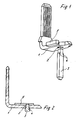
- one is essentially L-shaped curved busbar 1 is provided, in one leg of a receiving opening 2, in the illustrated embodiment with essentially square cross section, is provided, which, based on the two from the narrow sides of the conductor rail in the middle of the plane of the main surface the busbar 1 is.
- Other types of cross-section e.g. round or rectangular would be conceivable.
- This can be done accordingly in this receiving opening 2
- Shaped end of a pin 3 are inserted, so that too the pin 3 then centered in the plane of the main surface of the Busbar 1, in a vertical orientation to this main plane, stands.
- the connector pin 3 inserted from below.
- the connector pin 3 is permanently connected to the busbar 1. In an expedient embodiment, it is welded to it, in particular laser welded. For this, it is again expedient to have an edge of to allow both parts to be welded to protrude a little. A few tenths are sufficient to make it sufficient for laser welding deliquescent material of the connecting pin end is available. The The protruding end of the connecting pin is enlarged for illustration in FIG. 2 shown.
- the pin 3 is also with a form-fitting connector connected to the busbar 1.
- the illustrated embodiment has the pin 3 on two opposite Side contact shoulders 4, which after inserting on the lower Sit on the surface of the busbar 1. This ensures that the weld seam is not stressed in the application.
- the pin 3 is different depending on the desired connection technology designed, for example as a solder pin, wirewrap or in particular as a press-in pin for pressing into a printed circuit board. Due to the central position of the press-in pin and the positive connection can be high between the connector pin and the busbar Forces from the connector pin to the busbar without risk of damage be transferred as the welded connection between the pin and power rail is kept free from the forces. The high forces can be evenly distributed over a relatively large surface area of the busbar become.
- the busbar 1 their narrow outer sides opposite the receiving zone of the connecting pin 2 support surface pieces 5 for transferring the forces to adjacent Molded housing areas of an electrical connector.
- the outside support surface pieces 5 can be adapted to the circumstances the adjacent housing from the level of the busbar 1 are otherwise offset, as shown in the figures.
Landscapes
- Connections Effected By Soldering, Adhesion, Or Permanent Deformation (AREA)
- Coupling Device And Connection With Printed Circuit (AREA)
- Multi-Conductor Connections (AREA)
Description
Weitere bevorzugte Ausgestaltungen sind in den Unteransprüchen gekennzeichnet. Bevorzugt ist eine unlösbare Verbindung zwischen eingestecktem Anschlußstift und Stromschiene durch Verschweißen, hier insbesondere Laserverschweißen. Hierzu wiederum ist es zweckmäßig, den auf der einen Seite eingesteckten Anschlußstift auf der anderen Seite der Stromschiene ein klein wenig vorstehen zu lassen, um hier eine kleine Zone fließbaren Materiales für die Laserverschweißung zur Verfügung zu haben. Die Formschlußverbindung kann in einfacher Weise dadurch geschaffen werden, daß am Anschlußstift in seiner Steckzone Anlageschultern gebildet sind, die nach dem Einstecken auf der Stromschienenfläche aufsitzen. In weiterer zweckmäßiger Ausgestaltung können zu beiden Seiten der Aufnahmezone für den Anschlußstift außenseitig an die Stromschiene Auflagenflächenstücke angeformt sein, die im Bedarfsfall aus der Ebene der Stromschienenfläche im übrigen versetzt liegen können.
Es zeigen:
- Figur 1
- eine Stromschiene und einen Anschlußstift in sprengbildlicher, perspektivischer Darstellung,
- Figur 2
- einen Schnitt durch die Stromschiene mit unlösbar darin eingesetztem Anschlußstift.
Claims (8)
- Stromschiene (1) mit senkrecht zur Ebene einer ihrer Hauptflächen orientiertem Anschlußstift (3) für elektrische Verbinder, dadurch gekennzeichnet, daß der Anschlußstift (3) in eine Aufnahmeöffnung (2), die mittig in der Hauptfläche der Stromschiene (1) vorgesehen ist, eingesetzt und unlösbar mit der Stromschiene (1) verbunden ist, wobei der Anschlußstift (3) Anlageschultern (4) aufweist, die nach dem Einstecken formschlüssig auf der Fläche der Stromschiene (1) aufsitzen.
- Stromschiene nach Anspruch 1, dadurch gekennzeichnet, daß der Anschlußstift (3) mit der Stromschiene (1) verschweißt ist.
- Stromschiene nach Anspruch 2, dadurch gekennzeichnet, daß der Anschlußstift (3) mit der Stromschiene (1) laserverschweißt ist.
- Stromschiene nach einem der Ansprüche 2 oder 3, dadurch gekennzeichnet, daß bei durchgehender Aufnahmeöffnung (2) der Anschlußstift (3) mit seinem Ende geringfügig über oder unter die Stromschienenfläche vorstehend durchgesteckt ist.
- Stromschiene nach einem der vorhergehenden Ansprüche, dadurch gekennzeichnet, daß in der Stromschiene (1) mehrere Anschlußstifte (3) festgesetzt sind.
- Stromschiene nach einem der vorhergehenden Ansprüche, dadurch gekennzeichnet, daß der Anschlußstift (3) als Einpreßstift ausgebildet ist.
- Stromschiene nach einem der vorhergehenden Ansprüche, dadurch gekennzeichnet, daß die Stromschiene (1) und der Anschlußstift (3) aus unterschiedlichen Werkstoffen bestehen.
- Stromschiene nach einem der vorhergehenden Ansprüche, dadurch gekennzeichnet, daß an die Stromschiene (1) an ihren Schmalaußenseiten zu beiden Seiten der mittigen Aufnahmeöffnung (2) Auflagenflächenstücke (5) angeformt sind.
Applications Claiming Priority (2)
| Application Number | Priority Date | Filing Date | Title |
|---|---|---|---|
| DE29505107U DE29505107U1 (de) | 1995-03-25 | 1995-03-25 | Stromschiene mit Anschlußstift |
| DE29505107U | 1995-03-25 |
Publications (3)
| Publication Number | Publication Date |
|---|---|
| EP0735628A2 EP0735628A2 (de) | 1996-10-02 |
| EP0735628A3 EP0735628A3 (de) | 1997-08-13 |
| EP0735628B1 true EP0735628B1 (de) | 2001-10-10 |
Family
ID=8005898
Family Applications (1)
| Application Number | Title | Priority Date | Filing Date |
|---|---|---|---|
| EP96102703A Expired - Lifetime EP0735628B1 (de) | 1995-03-25 | 1996-02-23 | Stromschiene mit Anschlussstift |
Country Status (3)
| Country | Link |
|---|---|
| US (1) | US5951340A (de) |
| EP (1) | EP0735628B1 (de) |
| DE (2) | DE29505107U1 (de) |
Cited By (1)
| Publication number | Priority date | Publication date | Assignee | Title |
|---|---|---|---|---|
| WO2011069823A1 (de) | 2009-12-10 | 2011-06-16 | Robert Bosch Gmbh | Hochstromkontaktierung und korrespondierendes verfahren zur herstellung einer hochstromkontaktieranordnung |
Families Citing this family (29)
| Publication number | Priority date | Publication date | Assignee | Title |
|---|---|---|---|---|
| EP0887884B1 (de) | 1997-05-28 | 2003-04-02 | Autonetworks Technologies, Ltd. | Sammelschienenstruktur |
| FR2766628B1 (fr) * | 1997-07-22 | 1999-10-22 | Entrelec Sa | Peigne d'interconnexion pour alignement de bornes de raccordement electrique d'un appareillage et module(s) de logement d'appareillage correspondant(s) |
| ATE369031T1 (de) | 2004-04-08 | 2007-08-15 | Ebm Papst St Georgen Gmbh & Co | Anordnung mit einem kontaktelement |
| US7384522B2 (en) * | 2005-04-29 | 2008-06-10 | United Technologies Corporation | Ergonomic loading apparatus for electroplating processes |
| JP5054991B2 (ja) * | 2007-02-01 | 2012-10-24 | 三菱重工業株式会社 | バスバー接続構造およびインバータ一体型電動圧縮機 |
| DE102007029289A1 (de) * | 2007-06-18 | 2009-01-02 | E.G.O. Elektro-Gerätebau GmbH | Anschlussteil, Verfahren zur Herstellung eines solchen Anschlussteils und Schalteinrichtung mit mindestens einem solchen Anschlussteil |
| ATE472187T1 (de) * | 2008-04-08 | 2010-07-15 | Delphi Tech Inc | Verfahren zur herstellung einer elektrischen verbindung zwischen einer stromschiene und einer leiterplatte |
| DE102008018790A1 (de) * | 2008-04-15 | 2009-10-22 | Wobben, Aloys | Windenergieanlage mit Stromschienen |
| DE202009001854U1 (de) * | 2009-02-13 | 2010-07-15 | Weidmüller Interface GmbH & Co. KG | Steckerteil mit Steckeraufnahme |
| US8591248B2 (en) | 2011-01-20 | 2013-11-26 | Tyco Electronics Corporation | Electrical connector with terminal array |
| US20130178080A1 (en) * | 2012-01-09 | 2013-07-11 | Kostal Of America, Inc. | Soldered electronic components mounted solely on the top surface of a printed circuit board |
| DE102012214549A1 (de) * | 2012-08-16 | 2014-02-20 | Robert Bosch Gmbh | Kontaktsystem mit einem Einpresskontakt |
| CN104916944A (zh) * | 2014-03-14 | 2015-09-16 | 鸿富锦精密工业(武汉)有限公司 | 插接件及针脚 |
| CN104525706B (zh) * | 2014-11-28 | 2017-03-29 | 国网河南省电力公司洛阳供电公司 | 一种母排冲孔用模具装置 |
| EP3407425B1 (de) * | 2017-05-24 | 2020-04-22 | Mitsubishi Electric R&D Centre Europe B.V. | Anschlussmontage für power modul und power component |
| EP3639330B1 (de) | 2017-06-13 | 2025-03-26 | Samtec Inc. | Elektrischer kabelverbinder |
| WO2019018728A1 (en) | 2017-07-21 | 2019-01-24 | Samtec Inc. | ELECTRICAL CONNECTOR COMPRISING A LATCH |
| USD964291S1 (en) | 2017-07-21 | 2022-09-20 | Samtec, Inc. | Electrical connector |
| JP7004197B2 (ja) * | 2017-09-22 | 2022-01-21 | 株式会社オートネットワーク技術研究所 | 電気接続部材 |
| US11495917B2 (en) * | 2017-10-24 | 2022-11-08 | Samtec, Inc. | Right-angle electrical connector and electrical contacts for a right-angle connector |
| USD896183S1 (en) | 2018-01-08 | 2020-09-15 | Samtec, Inc. | Electrical cable connector |
| US11037749B2 (en) | 2018-05-04 | 2021-06-15 | Atom Power, Inc. | Selective coordination of solid-state circuit breakers and mechanical circuit breakers in electrical distribution systems |
| DE102019203166A1 (de) * | 2019-03-08 | 2020-09-10 | Zf Friedrichshafen Ag | Verbindung einer Stromschiene mit einem weiteren stromführenden Element |
| EP3984107A4 (de) * | 2019-06-13 | 2023-08-02 | Atom Power, Inc. | Festkörperschutzschalter mit galvanischer isolierung |
| US11791620B2 (en) | 2019-09-03 | 2023-10-17 | Atom Power, Inc. | Solid-state circuit breaker with self-diagnostic, self-maintenance, and self-protection capabilities |
| EP4026213A4 (de) | 2019-09-03 | 2024-04-03 | Atom Power, Inc. | Festkörperschalter mit selbstdiagnose, selbstwartung und selbstschutz |
| DE102021203954A1 (de) * | 2020-06-24 | 2021-12-30 | Robert Bosch Gesellschaft mit beschränkter Haftung | Stator einer elektrischen Maschine |
| US11476600B2 (en) * | 2020-12-18 | 2022-10-18 | Te Connectivity Solutions Gmbh | Electrical terminals with offset substrate mating portions |
| DE102022202817A1 (de) | 2022-03-23 | 2023-09-28 | Robert Bosch Gesellschaft mit beschränkter Haftung | Vorrichtung zur Entwärmung mindestens eines elektrischen Bauelements einer Leiterplatte |
Family Cites Families (8)
| Publication number | Priority date | Publication date | Assignee | Title |
|---|---|---|---|---|
| US2958069A (en) * | 1956-11-13 | 1960-10-25 | Gen Motors Corp | Electrical device |
| US2990533A (en) * | 1958-04-09 | 1961-06-27 | Stokes D Hughes | Terminal post for circuit board |
| US3061661A (en) * | 1960-03-31 | 1962-10-30 | Union Carbide Corp | Battery terminal assembly |
| US3410952A (en) * | 1964-11-04 | 1968-11-12 | Bunker Ramo | Electrical bus strip |
| US4159500A (en) * | 1977-11-17 | 1979-06-26 | Reliable Electric Company | Modular line protector |
| FR2606221B1 (fr) * | 1986-10-31 | 1989-08-25 | Legrand Sa | Bloc multiprises |
| JPH07110096B2 (ja) * | 1989-11-07 | 1995-11-22 | 矢崎総業株式会社 | ブスバーの相互接続構造 |
| DE9203941U1 (de) * | 1992-03-24 | 1992-05-07 | Schroff Gmbh, 7541 Straubenhardt | Vorrichtung zur Befestigung einer Stromschiene an einer Busplatine |
-
1995
- 1995-03-25 DE DE29505107U patent/DE29505107U1/de not_active Expired - Lifetime
-
1996
- 1996-02-16 US US08/602,273 patent/US5951340A/en not_active Expired - Fee Related
- 1996-02-23 DE DE59607857T patent/DE59607857D1/de not_active Expired - Lifetime
- 1996-02-23 EP EP96102703A patent/EP0735628B1/de not_active Expired - Lifetime
Cited By (2)
| Publication number | Priority date | Publication date | Assignee | Title |
|---|---|---|---|---|
| WO2011069823A1 (de) | 2009-12-10 | 2011-06-16 | Robert Bosch Gmbh | Hochstromkontaktierung und korrespondierendes verfahren zur herstellung einer hochstromkontaktieranordnung |
| DE102009047763A1 (de) | 2009-12-10 | 2011-06-16 | Robert Bosch Gmbh | Hochstromkontaktierung und korrespondierendes Verfahren zur Herstellung einer Hochstromkontaktieranordnung |
Also Published As
| Publication number | Publication date |
|---|---|
| EP0735628A3 (de) | 1997-08-13 |
| US5951340A (en) | 1999-09-14 |
| DE59607857D1 (de) | 2001-11-15 |
| EP0735628A2 (de) | 1996-10-02 |
| DE29505107U1 (de) | 1995-05-18 |
Similar Documents
| Publication | Publication Date | Title |
|---|---|---|
| EP0735628A2 (de) | Stromschiene mit Anschlussstift | |
| DE19938068C2 (de) | Leistungsverteilungszentrum | |
| DE69519682T2 (de) | Hybrides modulares elektrisches verbindersystem | |
| DE3917697C2 (de) | ||
| DE102017119287A1 (de) | Modularer Steckverbinder für Leiterplatten | |
| EP1680840B1 (de) | Flachsteckbuchse | |
| DE60001549T2 (de) | Elektrischer verbinder für ein ein/ausgabemodul | |
| DE102005033696B4 (de) | Kontaktelement | |
| DE3441416C2 (de) | Elektrische Steckverbindung | |
| DE4323426A1 (de) | Kontaktzange | |
| EP1755201B1 (de) | Elektrische Anschlussvorrichtung | |
| EP0086316B1 (de) | Steckkontaktvorrichtung zur Herstellung einer elektrischen Verbindung zwischen zwei Schienen | |
| DE3306019C2 (de) | Elektromagnetisches Relais | |
| DE19704437A1 (de) | Steckverbindung für elektrische Leitungen | |
| DE102019109471A1 (de) | Anordnung von modularen Leiterplattensteckverbindern | |
| EP0205504A1 (de) | Flachkabelverbinder. | |
| EP1432076B1 (de) | Elektrische Verbindungsklemme, insbesondere Reihenklemme | |
| DE102017112548B4 (de) | Elektrische kontakteinrichtung und metallische aufnahme für eine elektrische kontakteinrichtung | |
| EP1020954A2 (de) | Elektrische Anschlussklemme | |
| DE19828155A1 (de) | Elektrische Sammelschiene mit einem Anschluß | |
| WO2002027740A1 (de) | Bewegbarer kontaktträger für einen niederspannungs-leistungsschalter mit einem abstandhalter für die kontakthebel | |
| DE102006000958B4 (de) | Elektrisches Gerät | |
| DE102017105802B4 (de) | Steckverbindungselement, stromschnittstelle und damit ausgestatteter stromverteiler | |
| DE3730676C1 (en) | Electrical plug contact part | |
| DE2129587A1 (de) | Vorrichtung zum halten und kontaktieren von thermisch belasteten keramikwiderstaenden |
Legal Events
| Date | Code | Title | Description |
|---|---|---|---|
| PUAI | Public reference made under article 153(3) epc to a published international application that has entered the european phase |
Free format text: ORIGINAL CODE: 0009012 |
|
| AK | Designated contracting states |
Kind code of ref document: A2 Designated state(s): DE ES FR GB IT |
|
| PUAL | Search report despatched |
Free format text: ORIGINAL CODE: 0009013 |
|
| AK | Designated contracting states |
Kind code of ref document: A3 Designated state(s): DE ES FR GB IT |
|
| 17P | Request for examination filed |
Effective date: 19970712 |
|
| 17Q | First examination report despatched |
Effective date: 20000211 |
|
| GRAG | Despatch of communication of intention to grant |
Free format text: ORIGINAL CODE: EPIDOS AGRA |
|
| RIC1 | Information provided on ipc code assigned before grant |
Free format text: 7H 01R 31/08 A, 7H 01R 9/24 B, 7H 01R 12/16 B |
|
| GRAG | Despatch of communication of intention to grant |
Free format text: ORIGINAL CODE: EPIDOS AGRA |
|
| GRAH | Despatch of communication of intention to grant a patent |
Free format text: ORIGINAL CODE: EPIDOS IGRA |
|
| GRAH | Despatch of communication of intention to grant a patent |
Free format text: ORIGINAL CODE: EPIDOS IGRA |
|
| GRAA | (expected) grant |
Free format text: ORIGINAL CODE: 0009210 |
|
| AK | Designated contracting states |
Kind code of ref document: B1 Designated state(s): DE ES FR GB IT |
|
| PG25 | Lapsed in a contracting state [announced via postgrant information from national office to epo] |
Ref country code: IT Free format text: LAPSE BECAUSE OF FAILURE TO SUBMIT A TRANSLATION OF THE DESCRIPTION OR TO PAY THE FEE WITHIN THE PRE;WARNING: LAPSES OF ITALIAN PATENTS WITH EFFECTIVE DATE BEFORE 2007 MAY HAVE OCCURRED AT ANY TIME BEFORE 2007. THE CORRECT EFFECTIVE DATE MAY BE DIFFERENT FROM THE ONE RECORDED.SCRIBED TIME-LIMIT Effective date: 20011010 Ref country code: GB Free format text: LAPSE BECAUSE OF FAILURE TO SUBMIT A TRANSLATION OF THE DESCRIPTION OR TO PAY THE FEE WITHIN THE PRESCRIBED TIME-LIMIT Effective date: 20011010 Ref country code: FR Free format text: LAPSE BECAUSE OF FAILURE TO SUBMIT A TRANSLATION OF THE DESCRIPTION OR TO PAY THE FEE WITHIN THE PRESCRIBED TIME-LIMIT Effective date: 20011010 |
|
| REF | Corresponds to: |
Ref document number: 59607857 Country of ref document: DE Date of ref document: 20011115 |
|
| GBV | Gb: ep patent (uk) treated as always having been void in accordance with gb section 77(7)/1977 [no translation filed] |
Effective date: 20011010 |
|
| PG25 | Lapsed in a contracting state [announced via postgrant information from national office to epo] |
Ref country code: ES Free format text: LAPSE BECAUSE OF FAILURE TO SUBMIT A TRANSLATION OF THE DESCRIPTION OR TO PAY THE FEE WITHIN THE PRESCRIBED TIME-LIMIT Effective date: 20020430 |
|
| EN | Fr: translation not filed | ||
| PLBE | No opposition filed within time limit |
Free format text: ORIGINAL CODE: 0009261 |
|
| STAA | Information on the status of an ep patent application or granted ep patent |
Free format text: STATUS: NO OPPOSITION FILED WITHIN TIME LIMIT |
|
| 26N | No opposition filed | ||
| PGFP | Annual fee paid to national office [announced via postgrant information from national office to epo] |
Ref country code: DE Payment date: 20100219 Year of fee payment: 15 |
|
| REG | Reference to a national code |
Ref country code: DE Ref legal event code: R119 Ref document number: 59607857 Country of ref document: DE Effective date: 20110901 |
|
| PG25 | Lapsed in a contracting state [announced via postgrant information from national office to epo] |
Ref country code: DE Free format text: LAPSE BECAUSE OF NON-PAYMENT OF DUE FEES Effective date: 20110901 |