EP0735595A2 - Kondensator für eine integrierte Schaltung mit leitendem Graben - Google Patents
Kondensator für eine integrierte Schaltung mit leitendem Graben Download PDFInfo
- Publication number
- EP0735595A2 EP0735595A2 EP96103290A EP96103290A EP0735595A2 EP 0735595 A2 EP0735595 A2 EP 0735595A2 EP 96103290 A EP96103290 A EP 96103290A EP 96103290 A EP96103290 A EP 96103290A EP 0735595 A2 EP0735595 A2 EP 0735595A2
- Authority
- EP
- European Patent Office
- Prior art keywords
- layer
- bottom electrode
- semiconductor substrate
- electrode layer
- semiconductor
- Prior art date
- Legal status (The legal status is an assumption and is not a legal conclusion. Google has not performed a legal analysis and makes no representation as to the accuracy of the status listed.)
- Granted
Links
Images


Classifications
-
- H—ELECTRICITY
- H10—SEMICONDUCTOR DEVICES; ELECTRIC SOLID-STATE DEVICES NOT OTHERWISE PROVIDED FOR
- H10D—INORGANIC ELECTRIC SEMICONDUCTOR DEVICES
- H10D1/00—Resistors, capacitors or inductors
- H10D1/60—Capacitors
- H10D1/68—Capacitors having no potential barriers
Definitions
- the present invention relates, in general, to integrated circuits and, more particularly, to a capacitor structure for an integrated circuit that has a conductive trench.
- Capacitors are a fundamental component of a typical integrated circuit, and numerous capacitor structures exist depending on the particular circuit application desired.
- One such structure is known as a “bypass capacitor", which is used for example to reduce noise on voltage supply lines for integrated circuits operating at high frequencies.
- a typical prior bypass capacitor uses a top electrode of metal, a bottom electrode of heavy-doped polysilicon, and a dielectric of silicon nitride.
- a disadvantage of this prior capacitor is that the bottom electrode requires a metal contact formed through some of the overlying layers of the integrated circuit. This contact to the bottom electrode requires additional surface area on the integrated circuit and causes a significantly high series resistance across the bottom electrode. This is so because the bottom electrode typically has a sheet resistance of about 140 ohms/square, and the contact to the bottom electrode is usually made at only one end of the electrode. Thus, there exists a high resistance across the bottom electrode from the contacted end to the opposite end of the electrode.
- a further disadvantage of this prior capacitor is that either the metal contact to the top electrode or the metal contact to the bottom electrode must be routed across the top of the integrated circuit layout for connection to a ground or other lowest potential source.
- FIGs. 1-8 are cross-sectional views illustrating sequential steps in the manufacture of a capacitor according to the present invention.
- the present invention provides a capacitor for an integrated circuit comprising a conductive trench, disposed below a bottom electrode layer, that electrically connects the bottom electrode layer to a semiconductor substrate.
- a semiconductor layer having a conductivity type opposite to that of the semiconductor substrate and an insulating layer are disposed overlying the semiconductor substrate, and the conductive trench extends through both the insulating layer and the semiconductor layer down to the semiconductor substrate.
- the conductive trench permits the connection of the bottom electrode layer to a ground reference potential, which is connected to the substrate.
- FIGs. 1-8 are cross-sectional views illustrating the manufacture of a capacitor according to the present invention.
- a semiconductor layer 10 has been formed on a semiconductor substrate 12.
- Semiconductor layer 10 comprises a heavily-doped N-type epitaxial buried layer 18 and a lightly-doped N-type epitaxial layer 20.
- Semiconductor substrate 12 comprises a heavily-doped P-type semiconductor wafer 14 and an overlying lightly-doped P-type epitaxial layer 16.
- Wafer 14 is, for example, silicon with a bulk resistivity of 0.09-0.11 ohm-cm
- epitaxial layer 20 has a thickness of, for example, about one micron.
- Epitaxial layers 16, 18, and 20 are formed on wafer 14 using conventional techniques and are, for example, silicon.
- Isolation trenches 22 have been formed using known methods, such as reactive ion etching.
- a previously patterned hard-mask 24 defines the locations of isolation trenches 22 prior to etching, as is known.
- Hard-mask 24, for example, comprises an oxide layer 26 having a thickness of about 2,600 angstroms, a nitride layer 28 having a thickness of about 1,500 angstroms, a polysilicon layer (not shown) disposed directly underneath nitride layer 28 having a thickness of about 500 angstroms, and an oxide layer (not shown) disposed directly underneath the polysilicon layer (not shown) and on epitaxial layer 20 having a thickness of about 150 angstroms.
- Oxide layer 26 is, for example, formed from a tetraethylorthosilicate (TEOS) layer that has been cured in a furnace, as is known.
- TEOS tetraethylorthosilicate
- a liner oxide 30 is formed on the walls of trenches 22, and another polysilicon layer (not shown) is deposited and etched-back to provide a polysilicon fill 32 in trenches 22.
- liner oxide 30 has a thickness of about 3,000 angstroms as formed by a conventional furnace TEOS process, and the polysilicon layer (not shown) used to provide fill 32 is deposited to a thickness of about 8,000 angstroms.
- Isolation trenches 22 have, for example, a depth of about 5 microns, and polysilicon fill 32 is preferably un-doped.
- oxide layer 26 has been removed for example by reactive ion etching, and nitride layer 28 has been patterned to provide a nitride mask layer 34.
- Nitride layer 28 is patterned, for example, by reactive ion etching using the polysilicon layer (not shown) of hard-mask 24 as an etch-stop.
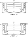
- nitride mask layer 34 has been used to grow a field isolation layer 36, such as an oxide, using a conventional process in order to define an active area 38.
- Field isolation layer 36 has a thickness, for example, of about 7,000 angstroms.
- nitride mask layer 34 and the remaining polysilicon and oxide layers (not shown) of hard-mask 24 are removed, for example, by wet etching to expose epitaxial layer 20 in active area 38.
- a screen oxide layer (not shown) of for example about 400 angstroms is grown in active area 38 of epitaxial layer 20. Then, an insulating layer 40 is formed over field isolation layer 36 and active area 38. Insulating layer 40 is, for example, silicon nitride having a thickness of about 1,000 angstroms.
- a heavily-doped P-type doped region 42 is optionally formed in epitaxial layer 20, for example, by ion implantation through insulating layer 40 using boron at an implant dose of about 8 x 10 13 /cm 2 and an energy of about 150 keV. Doped region 42 is activated by annealing, for example, in nitrogen at about 900 o C for 30 minutes. It should be appreciated that doped region 42 is contained substantially within epitaxial layer 20 and is defined at its edges by field isolation layer 36.
- an oxide layer 44 is formed to act as a hard-mask for defining and forming vertical trenches 46.
- Oxide layer 44 and insulating layer 40 are patterned using known methods, and vertical trenches 46 are then formed using, for example, reactive ion etching, as is known.
- Trenches 46 when fully formed extend through epitaxial layers 20, 18, and 16 to wafer 14 and are formed using substantially the same processing techniques used to form isolation trenches 22, as discussed previously.
- Doped region 42 preferably surrounds each of vertical trenches 46.
- Conductive material 48 may be formed by depositing a polysilicon layer (not shown) to a thickness of, for example, about 8,000 angstroms. This polysilicon layer is heavily doped with boron in-situ during deposition to be P-type, as is known, and then the polysilicon layer is etched back in a standard planarization process using, for example, reactive ion etching.
- Bottom electrode layer 52 is formed over and in contact with conductive trenches 50.
- Bottom electrode layer 52 may be formed by depositing a polysilicon layer to a thickness of about 1,800 angstroms.
- the polysilicon layer is, for example, preferably doped with boron by ion implantation at an implant dose of about 3.5 x 10 15 /cm 2 at an energy of 20 keV to provide a sheet resistance for bottom electrode layer 52 of about 140 ohms/square.
- conductive trenches 50 electrically connect bottom electrode layer 52 to semiconductor wafer 14 in the final capacitor and conductive material 48 is preferably heavily-doped P-type polysilicon.
- conductive trenches 50 are electrically connected to doped region 42 in the final capacitor.
- bottom electrode layer 52 has been patterned using, for example, reactive ion etching with insulating layer 40 as an etch-stop to define a bottom capacitor electrode.
- a dielectric layer 54 is formed, for example, by the deposition of a silicon nitride layer of a thickness of about 500 angstroms, and an oxide layer 56 is formed and patterned as is known to provide an opening for a later top electrode, as discussed below. It is preferred that oxide layer 56 be patterned using a wet etchant, with dielectric 54 acting as an etch-stop, to provide better control of the thickness of dielectric layer 54.
- FIG. 8 illustrates a fully-formed capacitor 58 according to the present invention.
- a top electrode layer 64 comprising a barrier layer 60 and a metal layer 62, has been formed on dielectric layer 54, as defined by oxide layer 56.
- barrier layer 60 is titanium tungsten deposited to a thickness of about 1,000 angstroms
- metal layer 62 is an aluminum/copper alloy of a thickness of about 6,500 angstroms.
- top electrode layer 64 may also include a polysilicon layer in contact with dielectric layer 54.
- capacitor 58 includes top electrode layer 64, dielectric layer 54, and bottom electrode layer 52.
- Conductive trenches 50 electrically connect bottom electrode layer 52 to semiconductor wafer 14.
- wafer 14 is electrically tied to a ground or other lowest reference potential source, as is known. Therefore, the bottom electrode of capacitor 58 is connected to the potential source without the need for a top-side contact.
- the back-side of semiconductor wafer 14 may have a metal layer disposed thereon for connection to the ground potential.
- Top electrode layer 64 is connected conventionally.
- An advantage according to the present invention is that the series resistance of bottom electrode layer 52 is significantly reduced compared to prior capacitors that require a top-side contact to the bottom electrode.
- conductive trenches 50 can be provided in a sufficient number so that there is no substantial series resistance between any portion of bottom electrode layer 52 and its closest connection to ground through wafer 14.
- doped region 42 is optional. Doped region 42 is preferred because it contributes to a reduction in the series resistance of bottom electrode layer 52 by providing a low resistance electrical path connecting conductive trenches 50.
- top electrode layer 64 can be a polysilicon layer underneath a metal layer, as used in a double-polysilicon capacitor structure.
- semiconductor wafer 14 is not limited to silicon, but may be other appropriate semiconductor materials.
- Isolation trenches 22 are also optional, but provide the advantage of containing any out-diffusion from optional doped region 42, when used. Thus, isolation trenches 22 permit a closer packing of capacitor 58 with other devices on an integrated circuit.
- Top electrode layer 64 due to the novel structure of capacitor 58, can be formed in some cases underneath a bonding pad or a metal power supply bus on an integrated circuit. This is possible because of the absence of any top-side contact for bottom electrode layer 52 as required in prior capacitors.
- An advantage of placing top electrode layer 64 underneath a bonding pad is a reduction in the layout area required for capacitor 58. This is especially advantageous for large capacitors having a capacitance greater than about 30 pF.
- semiconductor wafer 14 can be an N-type material with corresponding changes in the conductivity type of the other layers.
- capacitor 58 can be formed in structures not having isolation trenches 22. Further, conductive trenches 50 do not have to be etched, but can be formed by other techniques.
- This capacitor reduces the series resistance of the bottom electrode significantly compared to prior capacitors and reduces the layout area required for providing the capacitor in an integrated circuit. Also, the present invention eliminates the need for metal routing over the surface of the integrated circuit to connect one of the capacitor electrodes to a ground potential.
Landscapes
- Semiconductor Integrated Circuits (AREA)
Applications Claiming Priority (2)
| Application Number | Priority Date | Filing Date | Title |
|---|---|---|---|
| US08/411,194 US5574621A (en) | 1995-03-27 | 1995-03-27 | Integrated circuit capacitor having a conductive trench |
| US411194 | 1995-03-27 |
Publications (3)
| Publication Number | Publication Date |
|---|---|
| EP0735595A2 true EP0735595A2 (de) | 1996-10-02 |
| EP0735595A3 EP0735595A3 (de) | 1997-01-02 |
| EP0735595B1 EP0735595B1 (de) | 2000-07-12 |
Family
ID=23627963
Family Applications (1)
| Application Number | Title | Priority Date | Filing Date |
|---|---|---|---|
| EP96103290A Expired - Lifetime EP0735595B1 (de) | 1995-03-27 | 1996-03-04 | Kondensator für eine integrierte Schaltung mit leitendem Graben |
Country Status (4)
| Country | Link |
|---|---|
| US (1) | US5574621A (de) |
| EP (1) | EP0735595B1 (de) |
| JP (1) | JP3248608B2 (de) |
| DE (1) | DE69609224T2 (de) |
Cited By (1)
| Publication number | Priority date | Publication date | Assignee | Title |
|---|---|---|---|---|
| WO1998049722A1 (en) * | 1997-04-29 | 1998-11-05 | Telefonaktiebolaget Lm Ericsson (Publ) | Capacitors in integrated circuits |
Families Citing this family (20)
| Publication number | Priority date | Publication date | Assignee | Title |
|---|---|---|---|---|
| JP2000507045A (ja) * | 1996-03-22 | 2000-06-06 | テレフオンアクチーボラゲツト エル エム エリクソン | 導電ピンアレーで遮蔽された半導体デバイスとその製造方法 |
| US5898982A (en) * | 1997-05-30 | 1999-05-04 | Luminous Intent, Inc. | Thin film capacitors |
| US6087214A (en) * | 1998-04-29 | 2000-07-11 | Vlsi Technology, Inc. | Arrangement and method for DRAM cell using shallow trench isolation |
| US6150707A (en) * | 1999-01-07 | 2000-11-21 | International Business Machines Corporation | Metal-to-metal capacitor having thin insulator |
| JP3314760B2 (ja) * | 1999-05-24 | 2002-08-12 | 日本電気株式会社 | 静電保護素子、静電保護回路及び半導体装置 |
| US6858494B2 (en) * | 2002-08-20 | 2005-02-22 | Taiwan Semiconductor Manufacturing Company | Structure and fabricating method with self-aligned bit line contact to word line in split gate flash |
| US7037776B2 (en) | 2002-12-19 | 2006-05-02 | Taiwan Semiconductor Manufacturing Co., Ltd. | Single polysilicon process for DRAM |
| JP2004327619A (ja) | 2003-04-23 | 2004-11-18 | Toshiba Corp | 半導体集積回路装置及びその製造方法 |
| US6825078B1 (en) * | 2003-05-23 | 2004-11-30 | Taiwan Semiconductor Manufacturing Company | Single poly-Si process for DRAM by deep N well (NW) plate |
| US7040993B1 (en) * | 2004-04-30 | 2006-05-09 | Bert Lovitt | Amusement device with concealed images |
| US7547945B2 (en) | 2004-09-01 | 2009-06-16 | Micron Technology, Inc. | Transistor devices, transistor structures and semiconductor constructions |
| US7384849B2 (en) | 2005-03-25 | 2008-06-10 | Micron Technology, Inc. | Methods of forming recessed access devices associated with semiconductor constructions |
| US7282401B2 (en) | 2005-07-08 | 2007-10-16 | Micron Technology, Inc. | Method and apparatus for a self-aligned recessed access device (RAD) transistor gate |
| US7867851B2 (en) | 2005-08-30 | 2011-01-11 | Micron Technology, Inc. | Methods of forming field effect transistors on substrates |
| US7700441B2 (en) | 2006-02-02 | 2010-04-20 | Micron Technology, Inc. | Methods of forming field effect transistors, methods of forming field effect transistor gates, methods of forming integrated circuitry comprising a transistor gate array and circuitry peripheral to the gate array, and methods of forming integrated circuitry comprising a transistor gate array including first gates and second grounded isolation gates |
| US7602001B2 (en) | 2006-07-17 | 2009-10-13 | Micron Technology, Inc. | Capacitorless one transistor DRAM cell, integrated circuitry comprising an array of capacitorless one transistor DRAM cells, and method of forming lines of capacitorless one transistor DRAM cells |
| US7772632B2 (en) | 2006-08-21 | 2010-08-10 | Micron Technology, Inc. | Memory arrays and methods of fabricating memory arrays |
| US7589995B2 (en) | 2006-09-07 | 2009-09-15 | Micron Technology, Inc. | One-transistor memory cell with bias gate |
| US7923373B2 (en) | 2007-06-04 | 2011-04-12 | Micron Technology, Inc. | Pitch multiplication using self-assembling materials |
| US9281245B2 (en) * | 2012-12-28 | 2016-03-08 | Texas Instruments Incorporated | Latchup reduction by grown orthogonal substrates |
Family Cites Families (8)
| Publication number | Priority date | Publication date | Assignee | Title |
|---|---|---|---|---|
| DE3477532D1 (en) * | 1983-12-15 | 1989-05-03 | Toshiba Kk | Semiconductor memory device having trenched capacitor |
| EP0236089B1 (de) * | 1986-03-03 | 1992-08-05 | Fujitsu Limited | Einen Rillenkondensator enthaltender dynamischer Speicher mit wahlfreiem Zugriff |
| US4918502A (en) * | 1986-11-28 | 1990-04-17 | Hitachi, Ltd. | Semiconductor memory having trench capacitor formed with sheath electrode |
| JPS63158869A (ja) * | 1986-12-23 | 1988-07-01 | Oki Electric Ind Co Ltd | 半導体メモリ装置 |
| JPS63197370A (ja) * | 1987-02-12 | 1988-08-16 | Fujitsu Ltd | 半導体装置とその製造方法 |
| US5181089A (en) * | 1989-08-15 | 1993-01-19 | Matsushita Electric Industrial Co., Ltd. | Semiconductor memory device and a method for producing the same |
| JP3128834B2 (ja) * | 1991-01-28 | 2001-01-29 | 日本電気株式会社 | 半導体装置 |
| US5442584A (en) * | 1993-09-14 | 1995-08-15 | Goldstar Electron Co., Ltd. | Semiconductor memory device and method for fabricating the same dynamic random access memory device construction |
-
1995
- 1995-03-27 US US08/411,194 patent/US5574621A/en not_active Expired - Fee Related
-
1996
- 1996-03-04 DE DE69609224T patent/DE69609224T2/de not_active Expired - Fee Related
- 1996-03-04 EP EP96103290A patent/EP0735595B1/de not_active Expired - Lifetime
- 1996-03-27 JP JP09747496A patent/JP3248608B2/ja not_active Expired - Fee Related
Cited By (3)
| Publication number | Priority date | Publication date | Assignee | Title |
|---|---|---|---|---|
| WO1998049722A1 (en) * | 1997-04-29 | 1998-11-05 | Telefonaktiebolaget Lm Ericsson (Publ) | Capacitors in integrated circuits |
| US6100574A (en) * | 1997-04-29 | 2000-08-08 | Telefonaktiebolaget Lm Ericsson | Capacitors in integrated circuits |
| US6100133A (en) * | 1997-04-29 | 2000-08-08 | Telefonaktiebolaget Lm Ericsson | Capacitors in integrated circuits |
Also Published As
| Publication number | Publication date |
|---|---|
| US5574621A (en) | 1996-11-12 |
| JPH08274258A (ja) | 1996-10-18 |
| JP3248608B2 (ja) | 2002-01-21 |
| DE69609224T2 (de) | 2001-03-08 |
| DE69609224D1 (de) | 2000-08-17 |
| EP0735595A3 (de) | 1997-01-02 |
| EP0735595B1 (de) | 2000-07-12 |
Similar Documents
| Publication | Publication Date | Title |
|---|---|---|
| US5574621A (en) | Integrated circuit capacitor having a conductive trench | |
| US5479048A (en) | Integrated circuit chip supported by a handle wafer and provided with means to maintain the handle wafer potential at a desired level | |
| US6677636B2 (en) | Structure for reducing contact aspect ratios | |
| US6150721A (en) | Integrated circuit which uses a damascene process for producing staggered interconnect lines | |
| US6518616B2 (en) | Vertical gate top engineering for improved GC and CB process windows | |
| JP2002270697A (ja) | 電子構造体およびその製造方法 | |
| EP1229584B1 (de) | Halbleiterbauelement und zugehöriges Herstellungsverfahren | |
| US20020079537A1 (en) | Semiconductor on insulator device architecture and method of construction | |
| US6239010B1 (en) | Method for manually manufacturing capacitor | |
| US5254491A (en) | Method of making a semiconductor device having improved frequency response | |
| US6316833B1 (en) | Semiconductor device with multilayer interconnection having HSQ film with implanted fluorine and fluorine preventing liner | |
| KR19980024471A (ko) | 반도체 장치 및 그의 제조 방법 | |
| US5841182A (en) | Capacitor structure in a bonded wafer and method of fabrication | |
| US5514910A (en) | Semiconductor device having multi-level interconnection structure | |
| US5604659A (en) | Microelectronic device with centered storage capacitor cavity sized less than feature size | |
| US6150707A (en) | Metal-to-metal capacitor having thin insulator | |
| US20040259358A1 (en) | Self-aligned mask to reduce cell layout area | |
| US20250248056A1 (en) | Metal-insulator-metal capacitor structure and fabrication method thereof | |
| JP4931291B2 (ja) | 半導体装置 | |
| US6798042B2 (en) | Pin diode and method for fabricating the diode | |
| EP1025570A2 (de) | Verfahren zur anordnung von einem vergrabenen kondensator und so angeordneter vergrabener kondensator | |
| CN116314150B (zh) | 电容器及其制造方法、工作方法 | |
| WO1994025985A1 (en) | Method and semiconductor device with increased maximum terminal voltage | |
| KR100755627B1 (ko) | 반도체 소자의 캐패시터 제조 방법 | |
| EP1267397A1 (de) | Halbleitervorrichtung mit selbstjustiertem Kontakt und Verfahren zur Herstellung der Vorrichtung |
Legal Events
| Date | Code | Title | Description |
|---|---|---|---|
| PUAI | Public reference made under article 153(3) epc to a published international application that has entered the european phase |
Free format text: ORIGINAL CODE: 0009012 |
|
| AK | Designated contracting states |
Kind code of ref document: A2 Designated state(s): DE FR GB |
|
| PUAL | Search report despatched |
Free format text: ORIGINAL CODE: 0009013 |
|
| AK | Designated contracting states |
Kind code of ref document: A3 Designated state(s): DE FR GB |
|
| 17P | Request for examination filed |
Effective date: 19970702 |
|
| 17Q | First examination report despatched |
Effective date: 19990118 |
|
| GRAG | Despatch of communication of intention to grant |
Free format text: ORIGINAL CODE: EPIDOS AGRA |
|
| GRAG | Despatch of communication of intention to grant |
Free format text: ORIGINAL CODE: EPIDOS AGRA |
|
| GRAH | Despatch of communication of intention to grant a patent |
Free format text: ORIGINAL CODE: EPIDOS IGRA |
|
| GRAH | Despatch of communication of intention to grant a patent |
Free format text: ORIGINAL CODE: EPIDOS IGRA |
|
| GRAA | (expected) grant |
Free format text: ORIGINAL CODE: 0009210 |
|
| AK | Designated contracting states |
Kind code of ref document: B1 Designated state(s): DE FR GB |
|
| REF | Corresponds to: |
Ref document number: 69609224 Country of ref document: DE Date of ref document: 20000817 |
|
| ET | Fr: translation filed | ||
| PLBE | No opposition filed within time limit |
Free format text: ORIGINAL CODE: 0009261 |
|
| STAA | Information on the status of an ep patent application or granted ep patent |
Free format text: STATUS: NO OPPOSITION FILED WITHIN TIME LIMIT |
|
| 26N | No opposition filed | ||
| REG | Reference to a national code |
Ref country code: GB Ref legal event code: IF02 |
|
| PGFP | Annual fee paid to national office [announced via postgrant information from national office to epo] |
Ref country code: GB Payment date: 20050207 Year of fee payment: 10 |
|
| REG | Reference to a national code |
Ref country code: GB Ref legal event code: 732E |
|
| PGFP | Annual fee paid to national office [announced via postgrant information from national office to epo] |
Ref country code: FR Payment date: 20050302 Year of fee payment: 10 |
|
| PGFP | Annual fee paid to national office [announced via postgrant information from national office to epo] |
Ref country code: DE Payment date: 20050331 Year of fee payment: 10 |
|
| PG25 | Lapsed in a contracting state [announced via postgrant information from national office to epo] |
Ref country code: GB Free format text: LAPSE BECAUSE OF NON-PAYMENT OF DUE FEES Effective date: 20060304 |
|
| PG25 | Lapsed in a contracting state [announced via postgrant information from national office to epo] |
Ref country code: DE Free format text: LAPSE BECAUSE OF NON-PAYMENT OF DUE FEES Effective date: 20061003 |
|
| GBPC | Gb: european patent ceased through non-payment of renewal fee |
Effective date: 20060304 |
|
| REG | Reference to a national code |
Ref country code: FR Ref legal event code: ST Effective date: 20061130 |
|
| PG25 | Lapsed in a contracting state [announced via postgrant information from national office to epo] |
Ref country code: FR Free format text: LAPSE BECAUSE OF NON-PAYMENT OF DUE FEES Effective date: 20060331 |