EP0734894A2 - Vehicle body - Google Patents
Vehicle body Download PDFInfo
- Publication number
- EP0734894A2 EP0734894A2 EP96111343A EP96111343A EP0734894A2 EP 0734894 A2 EP0734894 A2 EP 0734894A2 EP 96111343 A EP96111343 A EP 96111343A EP 96111343 A EP96111343 A EP 96111343A EP 0734894 A2 EP0734894 A2 EP 0734894A2
- Authority
- EP
- European Patent Office
- Prior art keywords
- roof
- section
- roof section
- structure according
- sections
- Prior art date
- Legal status (The legal status is an assumption and is not a legal conclusion. Google has not performed a legal analysis and makes no representation as to the accuracy of the status listed.)
- Granted
Links
Images


Classifications
-
- B—PERFORMING OPERATIONS; TRANSPORTING
- B60—VEHICLES IN GENERAL
- B60J—WINDOWS, WINDSCREENS, NON-FIXED ROOFS, DOORS, OR SIMILAR DEVICES FOR VEHICLES; REMOVABLE EXTERNAL PROTECTIVE COVERINGS SPECIALLY ADAPTED FOR VEHICLES
- B60J7/00—Non-fixed roofs; Roofs with movable panels, e.g. rotary sunroofs
- B60J7/02—Non-fixed roofs; Roofs with movable panels, e.g. rotary sunroofs of sliding type, e.g. comprising guide shoes
- B60J7/04—Non-fixed roofs; Roofs with movable panels, e.g. rotary sunroofs of sliding type, e.g. comprising guide shoes with rigid plate-like element or elements, e.g. open roofs with harmonica-type folding rigid panels
- B60J7/053—Non-fixed roofs; Roofs with movable panels, e.g. rotary sunroofs of sliding type, e.g. comprising guide shoes with rigid plate-like element or elements, e.g. open roofs with harmonica-type folding rigid panels sliding with final closing motion having vertical component to attain closed and sealed condition, e.g. sliding under the roof
-
- B—PERFORMING OPERATIONS; TRANSPORTING
- B60—VEHICLES IN GENERAL
- B60J—WINDOWS, WINDSCREENS, NON-FIXED ROOFS, DOORS, OR SIMILAR DEVICES FOR VEHICLES; REMOVABLE EXTERNAL PROTECTIVE COVERINGS SPECIALLY ADAPTED FOR VEHICLES
- B60J7/00—Non-fixed roofs; Roofs with movable panels, e.g. rotary sunroofs
- B60J7/02—Non-fixed roofs; Roofs with movable panels, e.g. rotary sunroofs of sliding type, e.g. comprising guide shoes
- B60J7/04—Non-fixed roofs; Roofs with movable panels, e.g. rotary sunroofs of sliding type, e.g. comprising guide shoes with rigid plate-like element or elements, e.g. open roofs with harmonica-type folding rigid panels
- B60J7/047—Non-fixed roofs; Roofs with movable panels, e.g. rotary sunroofs of sliding type, e.g. comprising guide shoes with rigid plate-like element or elements, e.g. open roofs with harmonica-type folding rigid panels movable to overlapping or nested relationship
-
- B—PERFORMING OPERATIONS; TRANSPORTING
- B60—VEHICLES IN GENERAL
- B60J—WINDOWS, WINDSCREENS, NON-FIXED ROOFS, DOORS, OR SIMILAR DEVICES FOR VEHICLES; REMOVABLE EXTERNAL PROTECTIVE COVERINGS SPECIALLY ADAPTED FOR VEHICLES
- B60J7/00—Non-fixed roofs; Roofs with movable panels, e.g. rotary sunroofs
- B60J7/22—Wind deflectors for open roofs
Definitions
- the invention relates to a structure for passenger cars according to the preamble of claim 1.
- a passenger car with an attachment is known, DE 822 658, which comprises a closed roof, which impairs the unobstructed view of the occupants. This applies mutatis mutandis to the coupé attachment acc. DE 11 31 528.
- a motor vehicle roof structure is known, DE 34 39 880, in which a movable roof section is inserted into a body opening.
- the object of the invention is to design a body attachment of a passenger car in such a way that the view of the occupants into the open is improved and a relatively large roof area can be opened.
- the structure with its roof sections which can be made of glass and can be partially opened, form a purposeful combination of closed and open structure. Not only is the occupant's view upwards excellent, e.g. in order to observe processes and landscapes above the roof, but the movable roof sections provide good ventilation for the passenger compartment and the occupants can perceive the surrounding area, similar to an open vehicle.
- the movable roof sections are constructed in the manner of a sliding roof, the first roof section being a wind deflector and the second roof section being actual sunroof forms.
- the latter is designed to be adjustable under the third roof section by means of suitable kinematics and guides.
- the structure consists of easily producible frames and supports, which can be made of steel, plastic or light metal.
- the third roof section like the other roof sections, is a glass part, and the rear side windows are inserted into openings in the superstructure and fastened by gluing. Due to this design, the structure has sufficient rigidity with an acceptable weight.
- the structure with its essential parts can be a prefabricated module, the structure can have a convertible frame structure, which is held on the structure by screw connections.
- the module can be attached to a convertible body without any significant changes, so that a further type variant can be created with relatively little effort.
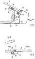
- the passenger car 1 comprises a body 2 which is supported by wheels 3.
- the structure 2 is formed by a base body 4 with a windshield 5 and a belt line 6.
- the base body 4 is provided with an attachment designed as an upper structure 7, which is connected to an upper windshield frame 7 ′ and the belt line 6 and covers a passenger compartment 9 with a roof 8.
- the base body 4 is provided on the longitudinal side of the vehicle with a door 12, which has a door body 13, a triangular window 14 and a sliding side window 15, the rear door window limit 16 of which is relatively upright, but is slightly inclined against the direction of travel B.
- Another side window 17 is arranged behind the door side window 15 on the top 6.
- the side window 17 has triangular basic shapes and tapers against the direction of travel B.
- the structure 7 has the side window frames 15, 17 delimiting lateral roof frames 18, between which - seen in the vehicle longitudinal direction C-C - a first roof section 20, a second roof section 21 and a third roof section 22 are provided one behind the other.
- the first roof section 20 is designed to be angularly movable between the operating positions Bst I and Bst II - FIGS. 1 and 2 and, in its operating position Bst II, acts as a wind deflector which can be hinged to the roof frame 18 or the windshield frame 7 '.
- the second roof section 21 is longitudinally movable in the manner of a sliding roof - operating positions Bst III and Bst IV - in such a way that it can be moved under the third roof section 22, namely into the operating position Bst IV, the third roof section 22 being fixed in the structure 7 is inserted.
- the roof sections 20, 21 and 22 are arranged flush with one another in the construction position or basic position, ie in the closed state, wherein between the roof sections 20 and 21 sealing body 23 are provided (Fig. 9).
- a rail 24 is provided which engages under the first roof section 20 with a web 25, a seal 26 being effective between the web 25 and the first roof section 20.
- a guide rail 27 (FIG. 6) is used, which is attached to the roof frame 18.
- One or more connecting devices Vv are provided between the guide rail 27 and the second roof section 21.
- the roof frame 18 comprises an outer shell 28 and an inner shell 29, the guide rail 27 being held on the inner shell 29.
- the second roof section 21 interacts with the inside 31 of a flange 32, which is formed by the outer shell 28 and the inner shell 29, by means of a sealing body 30.
- the sealing body 30 encompasses, with a receptacle 33, a flange 34 of a profiled carrier 35, which is fastened to the underside 36 of the second roof section 21 by suitable methods and is attached circumferentially to stiffen the relatively large-area roof section 21.
- the connecting device Vv comprises a lever mechanism which serves to move the roof section 21 on the one hand in the vehicle longitudinal direction C-C and on the other hand into the operating position Bst IV.
- all roof sections 20, 21 and 22 are made of sight glass; this can be multi-layer sun protection glass. Phototropic glass is also conceivable.
- a blind 37 (FIG. 6) can be provided on the inside of the roof sections 20, 21, which can be brought into a closed or cover position, for example, when the vehicle is at a standstill.
- coloring the glass for example black, on the outside of the roof section 21 in the region of the carrier 35 at 38, whereby on the one hand the carrier 35 is covered and on the other hand peculiar aesthetic effects can be achieved.
- the coloring can be provided as a border on all roof sections.
- the roof sections 20, 21, 22 seen in the vehicle longitudinal direction CC - in the passenger car of the present exemplary embodiment, if the second roof section 21 is guided behind the door window boundary 16 or an area above a rear passenger Ih, who sits behind a front occupant Iv.
- the length DL II and DL III of the second roof section 21 and the third roof section 22 is approximately four times greater than the length DL I of the first roof section 20 (FIG. 1).
- the roof sections 20 and 21 can be made as wide as possible, which results in a relatively narrow and light configuration of the roof frame.
- the support bracket 40 is U-shaped in cross section and holds the side window 17 (FIG. 7) in position by means of an adhesive body 41.
- the side window 17 is thus inserted into an opening 42 which is delimited by the side roof frame 18 of the column 39 and the support bracket 40.
- the opposite roof frames 18, which expand in cross-section according to FIG. 1 against the direction of travel B, which is illustrated by the lines DLo and DLu, are connected to a cross member 43 in the region of the third roof section 22, specifically adjacent to the second roof section 21 which the third roof section 22 rests on; it is held in position by gluing to the structure 7; the roof line 10 and the line DLo run approximately the same distance apart.
- the structure 7 forms with the roof sections 20, 21, 22, the side beams 18, 19, the columns 39, the cross member 43, the support beam 40 and the rear side window 17 a prefabricated module, which with the structure 2 or base body 4 by a or several screw connections 44 is connected.
- FIG. 8 An embodiment of a screw connection is shown in Fig. 8. Thereafter, the support bracket 40 is provided with an angle 45 which is brought up to a further angle 46 of the structure 2. A screw 47 is provided between the two angles 45, 46.
- the support bracket 40 is also connected on the one hand via an adhesive body 48 to the third roof section 22 and on the other hand is brought to a flange 50 of an inner cross member 51 of the structure 2 by means of a seal 49.
- the third roof section 22 connects to an outer cross member 53 with a sealing body 52.
Abstract
Description
Die Erfindung betrifft einen Aufbau für Personenwagen nach dem Oberbegriff des Patentanspruchs 1.The invention relates to a structure for passenger cars according to the preamble of claim 1.
Es ist ein Personenwagen mit einem Aufsatz bekannt, DE 822 658, der ein geschlossenes Dach umfaßt, was die freie Sicht der Insassen beeinträchtigt. Sinngemäß gilt dies für den Coupè-Aufsatz gem. der DE 11 31 528.A passenger car with an attachment is known, DE 822 658, which comprises a closed roof, which impairs the unobstructed view of the occupants. This applies mutatis mutandis to the coupé attachment acc. DE 11 31 528.
Darüber hinaus ist eine Kraftfahrzeug-Dachkonstruktion bekannt, DE 34 39 880, bei der ein beweglicher Dachabschnitt in eine Aufbauöffnung eingesetzt ist.In addition, a motor vehicle roof structure is known,
Aufgabe der Erfindung ist es, einen Aufbau-Aufsatz eines Personenwagens so zu gestalten, daß die Sicht der Insassen ins Freie verbessert wird und ein relativ großer Dachbereich zu öffnen ist.The object of the invention is to design a body attachment of a passenger car in such a way that the view of the occupants into the open is improved and a relatively large roof area can be opened.
Erfindungsgemäß wird diese Aufgabe durch die kennzeichnenden Merkmale des Patentanspruchs gelöst. Weitere, die Erfindung ausgestaltende Merkmale sind in den nachfolgenden Ansprüchen enthalten.According to the invention, this object is achieved by the characterizing features of the patent claim. Further features embodying the invention are contained in the following claims.
Die mit der Erfindung hauptsächlich erzielten Vorteile sind darin zu sehen, daß der Aufbau mit seinen Dachabschnitten, die aus Glas bestehen können und teilweise zu öffnen sind, eine zweckgerichtete Kombination aus geschlossenem und offenem Aufbau bilden. Dabei ist nicht nur die Sicht für die Insassen nach oben ausgezeichnet z.B. um Vorgänge und Landschaftsbilder über dem Dach zu beobachten, sondern es wird durch die beweglichen Dachabschnitte eine gute Be- und Entlüftung des Fahrgastraumes erzielt bzw. die Insassen können, ähnlich wie an einem offenen Fahrzeug, die sich ihnen bietende Umgebung wahrnehmen.The main advantages achieved with the invention are that the structure with its roof sections, which can be made of glass and can be partially opened, form a purposeful combination of closed and open structure. Not only is the occupant's view upwards excellent, e.g. in order to observe processes and landscapes above the roof, but the movable roof sections provide good ventilation for the passenger compartment and the occupants can perceive the surrounding area, similar to an open vehicle.
Die beweglichen Dachabschnitte sind nach Art eines Schiebedaches aufgebaut, wobei der erste Dachabschnitt ein Windabweiser ist und der zweite Dachabschnitt das eigentliche Schiebedach bildet. Letzterer ist mittels geeigneter Kinematik und Führungen unter den dritten Dachabschnitt verstellbar ausgebildet.The movable roof sections are constructed in the manner of a sliding roof, the first roof section being a wind deflector and the second roof section being actual sunroof forms. The latter is designed to be adjustable under the third roof section by means of suitable kinematics and guides.
Der Aufbau besteht aus leicht produzierbaren Rahmen und Trägern, die aus Stahl, Kunststoff oder Leichtmetall hergestellt sein können. Der dritte Dachabschnitt, er ist wie die anderen Dachabschnitte ein Glasteil, und die hinteren Seitenfenster sind in Öffnungen des Aufbaus eingesetzt und durch Kleben befestigt. Durch diese Bauweise hat der Aufbau ausreichende Steifigkeit bei vertretbarem Gewicht.The structure consists of easily producible frames and supports, which can be made of steel, plastic or light metal. The third roof section, like the other roof sections, is a glass part, and the rear side windows are inserted into openings in the superstructure and fastened by gluing. Due to this design, the structure has sufficient rigidity with an acceptable weight.
Schließlich kann der Aufbau mit seinen wesentlichen Teilen ein vorgefertigtes Modul sein, der Aufbau kann eine Cabrio-Rahmenstruktur aufweisen, durch Schraubverbindungen am Aufbau gehalten ist. Dadurch kann das Modul ohne nennenswerte Änderungen an einem Cabrio-Aufbau befestigt werden, so daß mit relativ geringem Aufwand eine weitere Typenvariante geschaffen ist.Finally, the structure with its essential parts can be a prefabricated module, the structure can have a convertible frame structure, which is held on the structure by screw connections. As a result, the module can be attached to a convertible body without any significant changes, so that a further type variant can be created with relatively little effort.
In der Zeichnung wird ein Ausführungsbeispiel der Erfindung gezeigt, das nachstehend näher beschrieben ist.In the drawing, an embodiment of the invention is shown, which is described in more detail below.
Es zeigt
- Fig. 1
- eine Seitenansicht eines Personenwagens mit dem erfindungsgemäßen Aufbau,
- Fig. 2
- eine Teilansicht der Fig. 1,
- Fig. 3
- eine Ansicht in Pfeilrichtung A der Fig. 1,
- Fig. 4
- einen Schnitt nach der Linie IV-IV der Fig. 3,
- Fig. 5
- eine Ansicht entsprechend Fig. 4,
- Fig. 6
- einen Schnitt nach der Linie VI-VI der Fig. 1 in größerem Maßstab,
- Fig. 7
- einen Schnitt nach der Linie VII-VII der Fig. 1 in größerem Maßstab,
- Fig. 8
- eine Einzelheit X der Fig. 1 in größerem Maßstab,
- Fig. 9
- eine Einzelheit Y der Fig. 1 in größerem Maßstab.
- Fig. 1
- a side view of a passenger car with the structure according to the invention,
- Fig. 2
- 2 shows a partial view of FIG. 1,
- Fig. 3
- 2 shows a view in the direction of arrow A in FIG. 1,
- Fig. 4
- a section along the line IV-IV of Fig. 3,
- Fig. 5
- 4 shows a view corresponding to FIG.
- Fig. 6
- 2 shows a section along the line VI-VI of FIG. 1 on a larger scale,
- Fig. 7
- 2 shows a section along the line VII-VII of FIG. 1 on a larger scale,
- Fig. 8
- a detail X of FIG. 1 on a larger scale,
- Fig. 9
- a detail Y of Fig. 1 on a larger scale.
Der Personenwagen 1 umfaßt einen Aufbau 2, der von Rädern 3 getragen wird. Der Aufbau 2 wird durch einen Grundkörper 4 mit einer Windschutzscheibe 5 und einer Gürtellinie 6 gebildet. Der Grundkörper 4 ist mit einem als oberer Aufbau 7 ausgebildeten Aufsatz versehen, der an einen oberen Windschutzscheibenrahmen 7' und die Gürtellinie 6 angeschlossen ist, und mit einem Dach 8 einen Fahrgastraum 9 abdeckt. Eine Dachlinie 10, die sich etwa entlang der Mittellängsebene des Personenwagens erstreckt, verläuft zwischen Windschutzscheibenrahmen 7' und einer Heckklappe 11 in einem entgegen der Fahrtrichtung B abfallenden, jedoch durchgängigen Bogen, so daß der Aufbau 2 die Form eines Coupés mit Fließheck aufweist.The passenger car 1 comprises a
Der Grundkörper 4 ist jeweils auf der Fahrzeuglängsseite mit einer Tür 12 versehen, die einen Türkörper 13, ein Dreiecksfenster 14 und ein verschiebbares Seitenfenster 15 aufweist, dessen hintere Türscheibenbegrenzung 16 zwar relativ aufrecht, jedoch entgegen der Fahrtrichtung B leicht geneigt ist. Ein weiteres Seitenfenster 17 ist hinter dem türseitigen Seitenfenster 15 am Aufsatz 6 angeordnet. Das Seitenfenster 17 besitzt dreieckige Grundformen und verjüngt sich entgegen der Fahrtrichtung B.The base body 4 is provided on the longitudinal side of the vehicle with a
Der Aufbau 7 besitzt die Seitenfenster 15, 17 begrenzende seitliche Dachrahmen 18, zwischen denen - in Fahrzeuglängsrichtung C-C gesehen - hintereinanderliegend ein erster Dachabschnitt 20, ein zweiter Dachabschnitt 21 und ein dritter Dachabschnitt 22 vorgesehen sind. Der erste Dachabschnitt 20 ist zwischen den Betriebsstellungen Bst I und Bst II - Fig. 1 und 2 - winkelbeweglich ausgebildet und wirkt in seiner aufgestellten Betriebsstellung Bst II als Windabweiser, der an dem Dachrahmen 18 oder dem Windschutzscheibenrahmen 7' scharniert sein kann. Der zweite Dachabschnitt 21 ist nach Art eines Schiebedaches längsbeweglich - Betriebsstellungen Bst III und Bst IV - ausgebildet derart, daß er sich unter den dritten Dachabschnitt 22 verschieben läßt, und zwar in die Betriebsstellung Bst IV, wobei der dritte Dachabschnitt 22 fest in den Aufbau 7 eingesetzt ist.The
Die Dachabschnitte 20, 21 und 22 sind in der Konstruktionslage oder Grundstellung, d.h. im geschlossenen Zustand oberflächenbündig zueinander angeordnet, wobei zwischen den Dachabschnitten 20 und 21 Dichtkörper 23 vorgesehen sind (Fig. 9). In diesem Bereich ist an der Unterseite zwischen Dachabschnitt 21 eine Schiene 24 vorgesehen, die mit einem Steg 25 den ersten Dachabschnitt 20 untergreift, wobei zwischen Steg 25 und dem ersten Dachabschnitt 20 eine Dichtung 26 wirksam ist.The
Um den zweiten Dachabschnitt 21 aus der Betriebsstellung Bst III in die Betriebsstellung Bst IV zu bewegen, dient eine Führungsschiene 27 (Fig, 6), die am Dachrahmen 18 angebracht ist. Zwischen der Führungsschiene 27 und dem zweiten Dachabschnitt 21 sind eine oder mehrere Verbindungsvorrichtungen Vv vorgesehen. In Fig. 6 ist dargestellt, daß der Dachrahmen 18 eine Außenschale 28 und eine Innenschale 29 umfaßt, wobei die Führungsschiene 27 an der Innenschale 29 gehalten ist. Der zweite Dachabschnitt 21 wirkt unter Vermittlung eines Dichtkörpers 30 mit der Innenseite 31 eines Flansches 32 zusammen, der durch die Außenschale 28 und die Innenschale 29 gebildet ist. Der Dichtkörper 30 umgreift mit einer Aufnahme 33 einen Flansch 34 eines profilierten Trägers 35, der an der Unterseite 36 des zweiten Dachabschnittes 21 durch geeignete Verfahren befestigt und umlaufend angebracht zur Versteifung des relativ großflächigen Dachabschnittes 21 dient. Die Verbindungsvorrichtung Vv umfaßt ein Hebelwerk, das zur Bewegung des Dachabschnittes 21 einerseits in Fahrzeugslängsrichtung C-C und andererseits in die Betriebsstellung Bst IV dient.In order to move the
Zur Sicherstellung einer guten Sicht für die Insassen des Personenwagens 1 sind sämtliche Dachabschnitte 20, 21 und 22 aus Sichtglas hergestellt; dabei kann es sich um mehrschichtiges Sonnenschutzglas handeln. Außerdem ist auch phototropes Glas denkbar. Darüber hinaus kann an der Innenseite der Dachabschnitte 20, 21 eine Jalousie 37 (Fig. 6) vorgesehen werden, die z.B. bei Stillstand des Fahrzeuges in eine geschlossene oder Abdeck-Position gebracht werden kann. Auch besteht die Möglichkeit, an der Außenseite des Dachabschnittes 21 im Bereich des Trägers 35 bei 38 das Glas z.B. schwarz einzufärben, wodurch zum einen der Träger 35 verdeckt wird und zum anderen eigentümliche ästhetische Effekte erzielbar sind. Die Einfärbung kann an allen Dachabschnitten umlaufend als Rand vorgesehen sein.To ensure a good view for the occupants of the passenger car 1, all
Günstige Verhältnisse für die Länge der Dachabschnitte 20, 21, 22 - in Fahrzeuglängsrichtung C-C gesehen - bei dem Personenwagen des vorliegenden Ausführungsbeispiel ergeben sich, wenn der zweite Dachabschnitt 21 bis hinter die Türscheibenbegrenzung 16 bzw. einen Bereich oberhalb eines Fond-Insassen Ih geführt wird, der hinter einem Front-Insassen Iv sitzt. Dabei ist die Länge DL II und DL III des zweiten Dachabschnittes 21 und des dritten Dachabschnittes 22 etwa vier Mal größer als die Länge DL I des ersten Dachabschnittes 20 (Fig. 1). Ferner können die Dachabschnitte 20 und 21 möglichst breit gestaltet sein, was eine relativ schmale und leichte Konfiguration der Dachrahmen zur Folge hat.Favorable conditions for the length of the
Vom Dachrahmen 18, der die Dachabschnitte 20, 21, 22 begrenzt, weggeführt, und zwar im Bereich der hinteren Türscheibenbegrenzung 16 ist eine Säule 39, die in einen oberhalb der Gürtellinie 6 verlaufenden Stützträger 40 des Aufbaus 7 mündet (Fig. 7), der entlang der Gürtellinie 6 zwischen den gegenüberliegenden Säulen 39 verläuft. Der Stützträger 40 ist im Querschnitt U-förmig ausgebildet und hält mittels eines Klebekörpers 41 das Seitenfenster 17 (Fig. 7) in Lage. Das Seitenfenster 17 ist also in eine Öffnung 42 eingesetzt, die vom seitlichen Dachrahmen 18 der Säule 39 und dem Stützträger 40 begrenzt wird.From the
Die gegenüberliegenden Dachrahmen 18, die sich gemäß Fig. 1 entgegen Fahrtrichtung B im Querschnitt erweitern, was durch die Linien DLo und DLu verdeutlicht wird, sind im Bereich des dritten Dachabschnittes 22, und zwar benachbart dem zweiten Dachabschnitt 21 mit einem Querträger 43 verbunden, auf dem der dritte Dachabschnitt 22 aufliegt; er ist durch Kleben am Aufbau 7 in Lage gehalten; die Dachlinie 10 und die Linie DLo verlaufen in etwa mit gleichem Abstand zueinander.The opposite roof frames 18, which expand in cross-section according to FIG. 1 against the direction of travel B, which is illustrated by the lines DLo and DLu, are connected to a
Der Aufbau 7 bildet mit den Dachabschnitten 20, 21, 22 den seitlichen Trägern 18, 19, den Säulen 39, dem Querträger 43, dem Stützträger 40 und der hinteren Seitenfenster 17 ein vorgefertigtes Modul, das mit dem Aufbau 2 bzw. Grundkörper 4 durch eine oder mehrere Schraubverbindungen 44 verbunden ist.The
Ein Ausführungsbeispiel einer Schraubverbindung ist in Fig. 8 dargestellt. Danach ist der Stützträger 40 mit einem Winkel 45 versehen, der an einen weiteren Winkel 46 des Aufbaues 2 herangeführt ist. Zwischen den beiden Winkeln 45, 46 ist eine Schraube 47 vorgesehen. Der Stützträger 40 ist darüber hinaus zum einen über einen Klebekörper 48 mit dem dritten Dachabschnitt 22 verbunden und zum anderen mittels einer Dichtung 49 an einen Flansch 50 eines inneren Querträgers 51 des Aufbaues 2 herangeführt. Schließlich schließt der dritte Dachabschnitt 22 mit einem Dichtkörper 52 an einen äußeren Querträger 53 an.An embodiment of a screw connection is shown in Fig. 8. Thereafter, the
Claims (39)
Applications Claiming Priority (3)
| Application Number | Priority Date | Filing Date | Title |
|---|---|---|---|
| DE4335653 | 1993-10-15 | ||
| DE4335653A DE4335653A1 (en) | 1993-10-15 | 1993-10-15 | Body for passenger cars |
| EP94115244A EP0648629B1 (en) | 1993-10-15 | 1994-09-28 | Vehicle body |
Related Parent Applications (2)
| Application Number | Title | Priority Date | Filing Date |
|---|---|---|---|
| EP94115244A Division EP0648629B1 (en) | 1993-10-15 | 1994-09-28 | Vehicle body |
| EP94115244.9 Division | 1994-09-28 |
Publications (3)
| Publication Number | Publication Date |
|---|---|
| EP0734894A2 true EP0734894A2 (en) | 1996-10-02 |
| EP0734894A3 EP0734894A3 (en) | 1996-11-06 |
| EP0734894B1 EP0734894B1 (en) | 1999-11-10 |
Family
ID=6500512
Family Applications (2)
| Application Number | Title | Priority Date | Filing Date |
|---|---|---|---|
| EP96111343A Expired - Lifetime EP0734894B1 (en) | 1993-10-15 | 1994-09-28 | Vehicle body |
| EP94115244A Expired - Lifetime EP0648629B1 (en) | 1993-10-15 | 1994-09-28 | Vehicle body |
Family Applications After (1)
| Application Number | Title | Priority Date | Filing Date |
|---|---|---|---|
| EP94115244A Expired - Lifetime EP0648629B1 (en) | 1993-10-15 | 1994-09-28 | Vehicle body |
Country Status (4)
| Country | Link |
|---|---|
| US (1) | US5544934A (en) |
| EP (2) | EP0734894B1 (en) |
| JP (1) | JP3538460B2 (en) |
| DE (3) | DE4335653A1 (en) |
Cited By (2)
| Publication number | Priority date | Publication date | Assignee | Title |
|---|---|---|---|---|
| EP1036684A2 (en) * | 1999-03-18 | 2000-09-20 | Dr.Ing. h.c.F. Porsche Aktiengesellschaft | Roof structure for a vehicle |
| EP1193094A3 (en) * | 2000-09-27 | 2003-03-05 | Webasto Vehicle Systems International GmbH | Device for open roof wind deflector |
Families Citing this family (24)
| Publication number | Priority date | Publication date | Assignee | Title |
|---|---|---|---|---|
| US5803534A (en) * | 1993-10-15 | 1998-09-08 | Dr. Ing. H.C.F. Porsche Ag | Passenger car with a transparent top assembly |
| DE4440730C1 (en) * | 1994-11-15 | 1995-11-23 | Porsche Ag | Roof construction for motor vehicle with moveable roof section |
| DE19510822A1 (en) * | 1995-03-24 | 1996-09-26 | Porsche Ag | Vehicle roof |
| DE19630812B4 (en) * | 1996-07-31 | 2011-09-15 | Webasto Ag | Transparent cover system for a vehicle interior |
| DE19634853C1 (en) * | 1996-08-28 | 1997-09-25 | Webasto Karosseriesysteme | Vehicle sunshine roof |
| US5947546A (en) * | 1996-10-22 | 1999-09-07 | Chrysler Corporation | Apparatus for attaching a soft top to a motor vehicle |
| DE19702336A1 (en) * | 1997-01-23 | 1998-07-30 | Webasto Karosseriesysteme | Opening roof for vehicle |
| DE19711352C1 (en) * | 1997-03-19 | 1998-04-23 | Porsche Ag | Removable hard top for convertible motor vehicle |
| DE19738828A1 (en) * | 1997-09-05 | 1999-03-11 | Daimler Benz Ag | Vehicle with a convertible top that can be opened |
| DE19941984C1 (en) | 1999-09-03 | 2000-10-19 | Porsche Ag | Multi-part sliding roof for a cross country vehicle sunroof has sections with independent movements to be set in a variety of configurations and is flush with the roof when closed without projecting guides |
| US6135535A (en) * | 1999-12-21 | 2000-10-24 | Larry J. Winget | Removable hard top for an automotive vehicle and method of making a composite removable hard top |
| DE10062718B4 (en) * | 2000-12-15 | 2005-02-10 | Cts Fahrzeug-Dachsysteme Gmbh | Vehicle roof with a sliding cover element |
| DE20103710U1 (en) * | 2001-03-02 | 2002-04-18 | Webasto Vehicle Sys Int Gmbh | Sun blind for a vehicle roof and vehicle roof with a movable cover |
| DE10117174A1 (en) * | 2001-04-06 | 2002-10-10 | Porsche Ag | Roof arrangement for a vehicle |
| DE10121888A1 (en) | 2001-05-05 | 2002-11-28 | Porsche Ag | Roof arrangement for a vehicle |
| DE10130267A1 (en) * | 2001-06-26 | 2003-01-09 | Webasto Vehicle Sys Int Gmbh | Motor vehicle sun roof with front and rear sections of which only front section retracts |
| GB0219114D0 (en) * | 2002-08-16 | 2002-09-25 | Mckenzie Martin A | A transparent/translucent double glazed roof adaptation |
| DE10343591B4 (en) * | 2003-09-18 | 2005-08-11 | Webasto Ag | Roof with opening and relocatable lid e.g. for vehicle, has cover locking mechanism and storage facility at vehicle roof adjustably stored with roof being able to be released below an adjacent roof section |
| DE102005021465B3 (en) | 2005-05-10 | 2007-02-01 | Magna Car Top Systems Gmbh | Roof for a motor vehicle |
| WO2008041072A2 (en) * | 2006-10-05 | 2008-04-10 | Craig Anthony Stephens | Means for accessing a vehicle in an emergency |
| DE102009002590A1 (en) * | 2009-04-23 | 2010-11-04 | Ford Global Technologies, LLC, Dearborn | Passenger car comprises openable and stowable roof, which has rigid roof part that is guided in parallel roof rails of side frame of body, and moved and lowered in direction of vehicle longitudinal axis |
| US9340096B2 (en) * | 2013-11-01 | 2016-05-17 | GM Global Technology Operations LLC | Vehicle and a method of attaching a sunroof assembly to the vehicle |
| US10297762B2 (en) | 2014-07-09 | 2019-05-21 | Universal Display Corporation | Organic electroluminescent materials and devices |
| US9381796B2 (en) * | 2014-11-12 | 2016-07-05 | Kurt P. Vogt | Split hard top convertible for motorized passenger vehicle |
Citations (3)
| Publication number | Priority date | Publication date | Assignee | Title |
|---|---|---|---|---|
| FR958347A (en) * | 1950-03-07 | |||
| GB2184404A (en) * | 1985-12-23 | 1987-06-24 | Webasto Werk Baier Kg W | Motor vehicle with a roof mounted ventilation device |
| GB2251223A (en) * | 1990-12-20 | 1992-07-01 | Rockwell Golde Gmbh | Sliding roof for an automobile |
Family Cites Families (15)
| Publication number | Priority date | Publication date | Assignee | Title |
|---|---|---|---|---|
| DE822658C (en) | 1948-01-28 | 1951-11-26 | Austin Motor Co Ltd | Vehicle upper part with folding roof to be exchanged with a fixed hood |
| DE1131528B (en) | 1960-11-24 | 1962-06-14 | Daimler Benz Ag | Passenger car with a removable coupe attachment |
| US4113303A (en) * | 1977-04-08 | 1978-09-12 | Yench Charles G | Roof structure for an automobile |
| DE3024619A1 (en) * | 1980-06-30 | 1982-01-28 | Fa. Wolfgang Hefelmann, 5620 Velbert | Hard top for cross country vehicle has integral stiffening ribs - giving permanent form and is esp. of glass fibre reinforced polyester |
| DE3429880A1 (en) * | 1984-08-14 | 1986-02-27 | Adam Opel AG, 6090 Rüsselsheim | Roof for motor vehicles, in particular for passenger cars |
| US4708389A (en) * | 1984-12-03 | 1987-11-24 | Mazda Motor Corporation | Open top type automobile body structure |
| DE3545869A1 (en) * | 1985-03-27 | 1986-10-09 | Webasto-Werk W. Baier GmbH & Co, 8035 Gauting | VEHICLE ROOF |
| IT8553228V0 (en) * | 1985-04-15 | 1985-04-15 | Gilardini Spa | SUNROOF FOR VEHICLES |
| JPS62155125A (en) * | 1985-12-27 | 1987-07-10 | Daihatsu Motor Co Ltd | Slide roof device for vehicle |
| US4852938A (en) * | 1987-02-05 | 1989-08-01 | Nissan Design International, Inc. | Transparent roof convertible automobile with retractable sunshade |
| US4801174A (en) | 1987-10-07 | 1989-01-31 | Nissan Design International, Inc. | Transparent roof convertible automobile |
| US4978161A (en) * | 1989-04-06 | 1990-12-18 | Schulze Todd M | Apparatus and method for applying a targa-like band to a convertible top vehicle |
| DE3929831C1 (en) * | 1989-09-05 | 1990-11-29 | Dr.Ing.H.C. F. Porsche Ag, 7000 Stuttgart, De | |
| DE9108228U1 (en) | 1991-07-04 | 1991-11-21 | Wanischeck-Bergmann, Axel, Dipl.-Ing., 8183 Rottach-Egern, De | |
| DE4222700C1 (en) | 1992-07-10 | 1993-06-03 | Axel Dipl.-Ing. 8183 Rottach-Egern De Wanischeck-Bergmann | Noise reducer for convertible motor vehicle - has pivoted plate on fastener, to cover space between windscreen frame and collapsible top |
-
1993
- 1993-10-15 DE DE4335653A patent/DE4335653A1/en not_active Ceased
-
1994
- 1994-09-28 DE DE59408919T patent/DE59408919D1/en not_active Expired - Lifetime
- 1994-09-28 EP EP96111343A patent/EP0734894B1/en not_active Expired - Lifetime
- 1994-09-28 EP EP94115244A patent/EP0648629B1/en not_active Expired - Lifetime
- 1994-09-28 DE DE59403002T patent/DE59403002D1/en not_active Expired - Lifetime
- 1994-10-12 JP JP24638394A patent/JP3538460B2/en not_active Expired - Lifetime
- 1994-10-17 US US08/324,395 patent/US5544934A/en not_active Expired - Lifetime
Patent Citations (3)
| Publication number | Priority date | Publication date | Assignee | Title |
|---|---|---|---|---|
| FR958347A (en) * | 1950-03-07 | |||
| GB2184404A (en) * | 1985-12-23 | 1987-06-24 | Webasto Werk Baier Kg W | Motor vehicle with a roof mounted ventilation device |
| GB2251223A (en) * | 1990-12-20 | 1992-07-01 | Rockwell Golde Gmbh | Sliding roof for an automobile |
Cited By (5)
| Publication number | Priority date | Publication date | Assignee | Title |
|---|---|---|---|---|
| EP1036684A2 (en) * | 1999-03-18 | 2000-09-20 | Dr.Ing. h.c.F. Porsche Aktiengesellschaft | Roof structure for a vehicle |
| EP1036684A3 (en) * | 1999-03-18 | 2001-05-02 | Dr.Ing. h.c.F. Porsche Aktiengesellschaft | Roof structure for a vehicle |
| US6279989B1 (en) | 1999-03-18 | 2001-08-28 | Dr. Ing. H.E.F. Porsche Aktiengesellschaft | Roof construction for a vehicle |
| EP1193094A3 (en) * | 2000-09-27 | 2003-03-05 | Webasto Vehicle Systems International GmbH | Device for open roof wind deflector |
| US6648406B2 (en) | 2000-09-27 | 2003-11-18 | Webasto Vehicle Systems International Gmbh | Mechanism for a wind deflector of an openable motor vehicle roof |
Also Published As
| Publication number | Publication date |
|---|---|
| EP0734894B1 (en) | 1999-11-10 |
| DE4335653A1 (en) | 1995-04-20 |
| JP3538460B2 (en) | 2004-06-14 |
| DE59403002D1 (en) | 1997-07-10 |
| US5544934A (en) | 1996-08-13 |
| DE59408919D1 (en) | 1999-12-16 |
| JPH07172185A (en) | 1995-07-11 |
| EP0648629B1 (en) | 1997-06-04 |
| EP0734894A3 (en) | 1996-11-06 |
| EP0648629A1 (en) | 1995-04-19 |
Similar Documents
| Publication | Publication Date | Title |
|---|---|---|
| EP0648629B1 (en) | Vehicle body | |
| DE4203229C2 (en) | Vehicle roof | |
| DE10021464B4 (en) | Vehicle with a vehicle roof to be opened | |
| EP1080963B1 (en) | Multi-part sliding roof for vehicles | |
| EP0845378B1 (en) | Vehicle roof structure, especially for passenger vehicles | |
| DE4438190C1 (en) | Two-shell folding roof for convertible motor vehicle | |
| EP0992384A2 (en) | Passenger vehicle with pivotable aerodynamic rear window frame | |
| EP1036688B1 (en) | Motor vehicle, particularly passenger vehicle | |
| EP0733506A1 (en) | Vehicle roof | |
| DE102006036453A1 (en) | Movable roof element for a passenger car | |
| DE10212241B4 (en) | Vehicle with a vehicle roof to be opened | |
| EP0416230A2 (en) | Motor car, particularly sports car | |
| DE102005021117A1 (en) | Vehicle convertible into various shapes, comprises roof and rear parts movable and storable in several ways | |
| EP0738629B1 (en) | Automotive vehicle, in particular convertible, with a rollover protection | |
| DE102006052069B4 (en) | Passenger car with an open construction | |
| DE4440730C1 (en) | Roof construction for motor vehicle with moveable roof section | |
| DE4113872A1 (en) | Folding roof for convertible car swivelably hinged to wind screen frame - is integral with rear window pane, both extending in common plane | |
| DE10211860B4 (en) | Vehicle roof with a sliding roof part | |
| DE10318076A1 (en) | Accident protection system for open-top motor vehicles rearranges an opening roof with long-edge support between a closed position over a passenger area and a stow-away position at a vehicle's rear | |
| DE10345122A1 (en) | Passenger car vehicle with open assembly e.g. for convertible vehicle, has open structure with form-rigid roof cover lying to cover vehicle and roof lies over roof area and raised due to movable belt | |
| EP1201496A1 (en) | Estate car | |
| DE102020112528A1 (en) | Motor vehicle with a body | |
| DE10357053A1 (en) | Cabriolet automobile with roll bars for side protection of passenger compartment incorporated in driver and passenger doors | |
| DE102005021465B3 (en) | Roof for a motor vehicle | |
| DE102016115457A1 (en) | Driver's cab with windscreen wiper |
Legal Events
| Date | Code | Title | Description |
|---|---|---|---|
| PUAI | Public reference made under article 153(3) epc to a published international application that has entered the european phase |
Free format text: ORIGINAL CODE: 0009012 |
|
| PUAL | Search report despatched |
Free format text: ORIGINAL CODE: 0009013 |
|
| AC | Divisional application: reference to earlier application |
Ref document number: 648629 Country of ref document: EP |
|
| AK | Designated contracting states |
Kind code of ref document: A2 Designated state(s): DE FR GB IT |
|
| AK | Designated contracting states |
Kind code of ref document: A3 Designated state(s): DE FR GB IT |
|
| 17P | Request for examination filed |
Effective date: 19961123 |
|
| 17Q | First examination report despatched |
Effective date: 19980415 |
|
| GRAG | Despatch of communication of intention to grant |
Free format text: ORIGINAL CODE: EPIDOS AGRA |
|
| GRAH | Despatch of communication of intention to grant a patent |
Free format text: ORIGINAL CODE: EPIDOS IGRA |
|
| GRAH | Despatch of communication of intention to grant a patent |
Free format text: ORIGINAL CODE: EPIDOS IGRA |
|
| ITF | It: translation for a ep patent filed |
Owner name: DE DOMINICIS & MAYER S.R.L. |
|
| GRAA | (expected) grant |
Free format text: ORIGINAL CODE: 0009210 |
|
| AC | Divisional application: reference to earlier application |
Ref document number: 648629 Country of ref document: EP |
|
| AK | Designated contracting states |
Kind code of ref document: B1 Designated state(s): DE FR GB IT |
|
| GBT | Gb: translation of ep patent filed (gb section 77(6)(a)/1977) |
Effective date: 19991117 |
|
| REF | Corresponds to: |
Ref document number: 59408919 Country of ref document: DE Date of ref document: 19991216 |
|
| ET | Fr: translation filed | ||
| PLBE | No opposition filed within time limit |
Free format text: ORIGINAL CODE: 0009261 |
|
| STAA | Information on the status of an ep patent application or granted ep patent |
Free format text: STATUS: NO OPPOSITION FILED WITHIN TIME LIMIT |
|
| 26N | No opposition filed | ||
| REG | Reference to a national code |
Ref country code: GB Ref legal event code: IF02 |
|
| REG | Reference to a national code |
Ref country code: FR Ref legal event code: TP |
|
| REG | Reference to a national code |
Ref country code: FR Ref legal event code: CD |
|
| REG | Reference to a national code |
Ref country code: FR Ref legal event code: TP |
|
| REG | Reference to a national code |
Ref country code: GB Ref legal event code: 732E Free format text: REGISTERED BETWEEN 20110310 AND 20110316 |
|
| REG | Reference to a national code |
Ref country code: GB Ref legal event code: 732E Free format text: REGISTERED BETWEEN 20110331 AND 20110406 |
|
| PGFP | Annual fee paid to national office [announced via postgrant information from national office to epo] |
Ref country code: DE Payment date: 20130829 Year of fee payment: 20 |
|
| PGFP | Annual fee paid to national office [announced via postgrant information from national office to epo] |
Ref country code: FR Payment date: 20130919 Year of fee payment: 20 Ref country code: GB Payment date: 20130919 Year of fee payment: 20 |
|
| PGFP | Annual fee paid to national office [announced via postgrant information from national office to epo] |
Ref country code: IT Payment date: 20130925 Year of fee payment: 20 |
|
| REG | Reference to a national code |
Ref country code: DE Ref legal event code: R071 Ref document number: 59408919 Country of ref document: DE |
|
| REG | Reference to a national code |
Ref country code: GB Ref legal event code: PE20 Expiry date: 20140927 |
|
| PG25 | Lapsed in a contracting state [announced via postgrant information from national office to epo] |
Ref country code: DE Free format text: LAPSE BECAUSE OF EXPIRATION OF PROTECTION Effective date: 20140930 |
|
| PG25 | Lapsed in a contracting state [announced via postgrant information from national office to epo] |
Ref country code: GB Free format text: LAPSE BECAUSE OF EXPIRATION OF PROTECTION Effective date: 20140927 |