EP0733376B1 - Membrane-Brustpumpe - Google Patents
Membrane-Brustpumpe Download PDFInfo
- Publication number
- EP0733376B1 EP0733376B1 EP96301970A EP96301970A EP0733376B1 EP 0733376 B1 EP0733376 B1 EP 0733376B1 EP 96301970 A EP96301970 A EP 96301970A EP 96301970 A EP96301970 A EP 96301970A EP 0733376 B1 EP0733376 B1 EP 0733376B1
- Authority
- EP
- European Patent Office
- Prior art keywords
- pump
- diaphragm
- lever
- breast
- diaphragm base
- Prior art date
- Legal status (The legal status is an assumption and is not a legal conclusion. Google has not performed a legal analysis and makes no representation as to the accuracy of the status listed.)
- Expired - Lifetime
Links
Images

Classifications
-
- A—HUMAN NECESSITIES
- A61—MEDICAL OR VETERINARY SCIENCE; HYGIENE
- A61M—DEVICES FOR INTRODUCING MEDIA INTO, OR ONTO, THE BODY; DEVICES FOR TRANSDUCING BODY MEDIA OR FOR TAKING MEDIA FROM THE BODY; DEVICES FOR PRODUCING OR ENDING SLEEP OR STUPOR
- A61M1/00—Suction or pumping devices for medical purposes; Devices for carrying-off, for treatment of, or for carrying-over, body-liquids; Drainage systems
- A61M1/06—Milking pumps
- A61M1/069—Means for improving milking yield
- A61M1/0697—Means for improving milking yield having means for massaging the breast
-
- A—HUMAN NECESSITIES
- A61—MEDICAL OR VETERINARY SCIENCE; HYGIENE
- A61M—DEVICES FOR INTRODUCING MEDIA INTO, OR ONTO, THE BODY; DEVICES FOR TRANSDUCING BODY MEDIA OR FOR TAKING MEDIA FROM THE BODY; DEVICES FOR PRODUCING OR ENDING SLEEP OR STUPOR
- A61M1/00—Suction or pumping devices for medical purposes; Devices for carrying-off, for treatment of, or for carrying-over, body-liquids; Drainage systems
- A61M1/80—Suction pumps
- A61M1/81—Piston pumps, e.g. syringes
-
- A—HUMAN NECESSITIES
- A61—MEDICAL OR VETERINARY SCIENCE; HYGIENE
- A61M—DEVICES FOR INTRODUCING MEDIA INTO, OR ONTO, THE BODY; DEVICES FOR TRANSDUCING BODY MEDIA OR FOR TAKING MEDIA FROM THE BODY; DEVICES FOR PRODUCING OR ENDING SLEEP OR STUPOR
- A61M1/00—Suction or pumping devices for medical purposes; Devices for carrying-off, for treatment of, or for carrying-over, body-liquids; Drainage systems
- A61M1/80—Suction pumps
- A61M1/82—Membrane pumps, e.g. bulbs
-
- A—HUMAN NECESSITIES
- A61—MEDICAL OR VETERINARY SCIENCE; HYGIENE
- A61M—DEVICES FOR INTRODUCING MEDIA INTO, OR ONTO, THE BODY; DEVICES FOR TRANSDUCING BODY MEDIA OR FOR TAKING MEDIA FROM THE BODY; DEVICES FOR PRODUCING OR ENDING SLEEP OR STUPOR
- A61M2205/00—General characteristics of the apparatus
- A61M2205/07—General characteristics of the apparatus having air pumping means
- A61M2205/071—General characteristics of the apparatus having air pumping means hand operated
- A61M2205/073—Syringe, piston type
-
- A—HUMAN NECESSITIES
- A61—MEDICAL OR VETERINARY SCIENCE; HYGIENE
- A61M—DEVICES FOR INTRODUCING MEDIA INTO, OR ONTO, THE BODY; DEVICES FOR TRANSDUCING BODY MEDIA OR FOR TAKING MEDIA FROM THE BODY; DEVICES FOR PRODUCING OR ENDING SLEEP OR STUPOR
- A61M2205/00—General characteristics of the apparatus
- A61M2205/07—General characteristics of the apparatus having air pumping means
- A61M2205/071—General characteristics of the apparatus having air pumping means hand operated
- A61M2205/075—Bulb type
Definitions
- This invention relates to a manually operated breast pump and particularly to a breast pump which can be operated single handedly by the user.
- This pump comprises a body including a breast and nipple receiving part and a base part enabling the connection thereto of a container to collect expressed milk.
- the body houses manually operable means to create a negative pressure at the nipple sufficient to express milk therefrom, said means including a valve system operable to pressurise the volume in the body but not the volume in the milk collecting container when connected to the base part.
- the pump is constructed and arranged so that it can be held against the breast and nipple by the user with one hand only, said same hand being used to manually operate the lever connected to a piston which reciprocates in a barrel located in the body to create the negative pressure at the nipple.
- a manually operated breast pump according to the invention is characterised in that the actuating means is mounted on the body and is configured to be operated with the user's hand, and in that the connector means releasably connects the actuating means to the diaphragm base.
- the diaphragm base is mounted inside the body but it can be mounted externally thereof.
- valve means are located in the body so that said negative pressure is created in the pump body only and not in the container for the expressed milk when connected thereto.
- the actuating means includes a lever which has a handle portion and a nose portion, the handle portion being pivotally mounted on the body and the nose portion engaging with the connector means, the arrangement being such that the handle moves relative to the body in a direction generally normal thereto as a result of which the nose portion moves axially of the body.
- the connector comprises a projection which extends upwardly from the diaphragm base for engagement by the actuator means.
- the diaphragm base is cup-shaped and the connector is a post which extends upwardly therefrom.
- the post can be integrally formed with the diaphragm base but it is preferably a separate component which is releasably fitted thereto.
- the diaphragm base is releasably retained in the body. In one embodiment, this is achieved using a retaining member or holder which fits into the body to hold the diaphragm base in position whereby it makes a fluidtight seal therewith.
- the body has an upstanding annular lip which is received in an annular rebate formed around the circumference of the diaphragm base, the retaining member holding the diaphragm base in sealing engagement therewith.
- the retaining member is a cover which fits on the top of the body to enclose the diaphragm base, said cover having an annular sealing surface which engages with the outer surface of the diaphragm base to hold it in sealing engagement with the annular lip of the body.
- the cover includes retaining means to hold said cover in position on the body.
- said retaining means comprise resilient tabs on the cover which engage with projections extending from the body.
- the lever includes a handle portion and the holder has a pivot support projecting therefrom which pivotally mounts the lever handle thereon.
- the nose portion of the lever includes connection means releasably connecting the lever either directly or indirectly to the diaphragm base.
- the connection means comprises a forked end on the nose portion of the lever which engages with a connector protruding from the diaphragm base.
- the connector has an enlarged head portion provided at one end thereof which is engaged by said forked end of the lever. The lever can however have a hole in its nose portion to receive said enlarged head on the connector.
- the lever can be moved against the action of a spring located between the connector and a cover fitted to the top of the pump to enclose the nose portion of the lever but preferably no spring is used and instead the resilience of the diaphragm base provides the return biasing force assisted by atmospheric pressure.
- the valve means preferably comprises a valve fitted in an aperture in a wall extending across the body adjacent where it is attached to the milk collecting container.
- the body includes a moulded portion provided with threads to enable it to be screwed directly to a milk collecting container such as a plastic bottle of known type but it can be mounted on the container in any convenient known way.
- a milk collecting container such as a plastic bottle of known type but it can be mounted on the container in any convenient known way.
- the neck portions of known plastic bottles vary in diameter, rather than producing a pump with a different threaded portion in the base thereof to fit each different bottle neck size, it is envisaged within the scope of the invention to provide the base of the pump body with releasable connecting means for attaching it to an adaptor which itself is configured to fit various different bottle neck diameters.
- the adaptor can first be fitted to the bottle and the pump body can then be attached to the adaptor, for instance using a bayonet fitting or some other known releasable connection arrangement.
- a convenient way of attaching the adaptor to the bottle would be to provide the tubular body of the adaptor with an outwardly extending annular flange which can be sandwiched between the upper rim of the bottle and the screw cap normally used to attach the teat to the bottle, the body of the adaptor extending through a central hole in the screw cap.
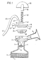
- a single handed breast pump comprising a moulded plastics body 1 including a cup-shaped upper portion 2 and a lower portion 3 with threads formed on the internal surface thereof so that the body can be screwed onto a milk collecting vessel (not shown) e.g. a baby feed bottle or some other suitable container.
- the body includes an internal dividing wall 6 which separates the cup-shaped upper portion 2 from the lower portion 3 and is formed with a central hole 7 in which a plug valve 11 is mounted.
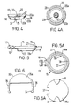
- the valve 11 comprises end portions 11a and 11b (see Figure 2) connected by a central section 11c whose length is greater than the thickness of the dividing wall 6 so that the plug valve 11 can move axially in the hole 7 by the distance separating the end sections 11a and 11b thereof. The reason for this axial movement will be described hereafter.
- An inlet trumpet 8 is formed at one side of the cup-shaped upper section 2 of the body 1 and its free end is enlarged to provide a conical section 9 shaped to receive the breast and nipple of a user.
- An inlet opening 10 (see Figure 1) is formed in the upper cup-shaped section 2 to place the interior of the body 1 in communication with the inlet trumpet 8.
- the interior surface of the cup-shaped section 2 is moulded to include two contoured surfaces 13 and 14 (see Figure 1) the purpose of which will be described shortly.
- FIG. 1 there is shown a circular moulded rigid plastics diaphragm holder 15 having an upper section 18 of a first diameter and a lower section 19 of a second diameter connected by an intermediate step section 21.
- the cross sectional shape of the holder 15 is generally frusto conical.
- the bottom edge of the lower section 19 defines a central aperture 22.
- An extension 16 extends laterally from one side of the holder 15 and has a hinge pivot 17 formed at one end thereof.
- the external contours of the holder 15 and in particular the contours of the upper and lower sections 18 and 19 are shaped so that they fit exactly inside the diaphragm 20 and hold it against surfaces 13 and 14 of the cup-shape portion 2 of the body 1 to make a fluidtight seal therewith.
- a cup-shaped diaphragm 20 which comprises an upper section 20a connected to a lower section 20b by means of a stepped portion 28.
- the diaphragm 20 also includes a radially inwardly extending bottom wall 20c extending from the lower wall 20 and having a central aperture 25 formed therein.
- a moulded plastics stem connector 26 is formed with a bottom annular rebate 27 therein which mounts the connector 26 in the hole 25.
- the connector 26 is also formed with an upper annular rebate 30 the purpose of which will be described shortly.
- the upper part 29 of the stem connector has moulded thereon an upstanding projection 31 which serves to locate a spring 32 (see Figures 1 and 2).
- a cap 35 which comprises a part spherical cover portion 35a having a pair of downwardly extending legs 36 attached thereto at locations diametrically opposite each other.
- the free end of each leg 36 includes an inwardly directed lip 37 to engage with the body 2 and retain the cap 35 thereon.
- a cut-out portion 37 is provided on one side of the cap 35 to provide access for lever 40.
- the moulded plastics lever 40 is illustrated in more detail in Figures 1-3 and comprises a handle 41 connected to a nose portion 42 having a forked end 43 defining a gap 44 therein (see Figure 3).
- Figure 1 illustrates the various components of the breast pump of the present invention in their unassembled condition whereas Figure 2 shows them in their assembled condition.
- the diaphragm 20 is mounted directly in the body 2 and the holder 15 is then fitted into the cup-shaped portion 2 of the body 1 to hold the diaphragm in position whereby it makes a fluidtight seal with the annular surfaces 13 and 14 of the body 2.
- the connector 26 is mounted in the central aperture 25 in the diaphragm and extends upwardly therefrom.
- the handle 41 is mounted relative to the cup-shaped portion 2 so that its forked nose 43 locates in the rebate 30 under the top part 29 of the stem connector 26.
- the cap 35 is attached to the upper region of the cup-shaped body portion 2 and retained in position thereon by means of the downwardly depending legs 36 whose ends 37 engage with suitable recesses (not shown) formed on the body 1.
- a coil spring 32 is mounted on the spring locating means 31 on the top 29 of the actuator.
- the inside surface of the cover 35 is formed with an annular wall 33 (see Figure 2) to provide a locating recess on the undersurface of the cap 35 to receive the other end of the spring 32.
- the spring 32 acts between the cover 35 and the forked nose 43 of the lever 41 to bias the lever 41 into its rest position shown in Figure 2.
- the lever 41 extends from the interior of the body 1 to the exterior thereof through the gap 37 provided in the cover 35.
- the lower portion 33 is screwed on to a suitable milk collecting container (not shown) such as a baby bottle of known type and the pump is now ready to use.
- a suitable milk collecting container such as a baby bottle of known type
- the user first inserts her breast and nipple into the conical portion 9 at the end of the inlet trumpet 8 and holds the body 1 with the milk collecting container (not shown) connected thereto against her breast.
- she Due to the design of the breast pump, she is able to place her thumb around the barrel portion 1 of the body and her fingers over the handle 41. She can then apply pressure to the handle 41 to move it in the direction of arrow A (see Figure 2) which is generally laterally with respect to the body 1 and towards her breast.
- Lactation generally results if a vacuum is created in the region of the nipple but the flow can be improved if the breast itself is stimulated in some way.
- Lactation is best promoted if an alternating pressure is created in the nipple region in a cyclic fashion. In other words, it is preferable to create a negative pressure initially and then reduce or release it preferably by venting to atmosphere and the pump just described operates in this way.
- the diaphragm 20 could be moulded of a material which is sufficiently resilient to ensure that the lever 41 returns to its rest position shown in Figure 2 on release of the pressure thereon using the natural resilience of the diaphragm itself and the effects of atmospheric pressure. It will be appreciated that the force required to overcome the resilience of the diaphragm 20 to deform and raise it will be less when the return spring is omitted so a shorter handle 41 can be used. This not only saves space and materials but it makes the pump much easier to use. For instance experiments have shown that as much as between 5 and 10 times less pressure is needed to raise the diaphragm than is the case when a return spring is used.
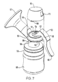
- Figure 7 illustrates a single handed breast pump comprising a moulded plastic body 50 with a diaphragm 51 mounted thereon at its upper end.
- a pivotally mounted lever 53 having a nose portion 52 is attached to a connector 54 protruding from a central hole 51a in the diaphragm 51.
- a cap 55 encloses the diaphragm 51 and the nose portion of fork 52 of lever 53.
- the body 50 has an inlet 56 with a conical attachment 57 fitted thereto to receive the user's breast and nipple.
- the body is releasably connected to an adaptor 58 which receives a screw cap 59 to enable it to be screwed into collecting vessel 60.
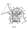
- the pump shown in Figures 7 and 8 will now be described in more detail.
- the upper region of the body 50 is formed with an annular shoulder 61 over which a rolled over annular lip 62 of the diaphragm 51 is fitted.
- the diaphragm 51 is made from a resiliently deformable material such as silicone rubber and has a central hole 51a therethrough in which a moulded plastics connector 54 is fitted.
- the diaphragm 51 is mounted in a lower annular rebate 54a formed at the base of the connector 54 which also includes an upper annular rebate 63 which receives and locates slotted end 64 of the nose portion 52 of the moulded plastics lever 53.
- the moulded plastics lever 53 also includes an operating hand portion 65 pivotally mounted on pivot 66 formed on the end of a support arm 67 extending laterally from the body 50 and integrally formed therewith.
- the support 67 is offset with respect to the longitudinal axis of the body 50.
- the moulded plastics cap 55 is attached to the body 50 by means of a pair of diametrically opposed downwardly extending clip 68 (see Figure 7) formed on its lower edge which engages with and receive diametrically opposed tabs 69 formed on outwardly projecting rim 70 of the body 50 (see Figure 7).
- the lower internal annular face 71 of cap 55 is shaped to make a seal with the external face of the annular lip 62 of the diaphragm 51 to firmly retain and press against the annular shoulder 61 of the body 50 and create a fluidtight seal between the diaphragm 51 and the body 50.
- the cap 55 is also formed with an access opening 73 to enable the handle portion 65 of the lever 53 to protrude through the cap 55 to allow operation thereof.
- the body 50 has a tubular lower part 74 with a screw thread 75 thereon which cooperates with screw threads 74a formed on the inside wall of the upper end of a tubular adaptor 58 in known manner thereby providing a releasable connection between the body 50 and the adaptor 58.
- a releasable bayonet type connection could however be used.
- the diameter of the upper end of the adaptor 58 is less than that of hole 76 formed in the top surface of moulded plastic screw cap 59.
- the cap 59 fits over the upper end of the adaptor 58 and rests on an annular flange 77 protruding outwardly from the body of the adaptor 58.
- the plastic screw cap 59 has threads formed on the internal surface thereof so that the adaptor 58 and body 50 can be connected to a collecting vessel 60 (see Figure 8) such as a baby feed bottle or other suitable container.
- the body 50 also includes an internal dividing wall 78 which separates the body 50 from its lower part 74 and is formed with a central hole in which a button valve 80 is mounted.
- the valve 80 comprises spaced end portions 81 and 82 connected by a central core 83 whose length is greater than the thickness of the internal dividing wall 78 and of a diameter less than that of the central hole in it so that the valve 80 can move axially in the hole 79 by an amount equal to the distance separating the end portions 81 and 82.
- the body 50 has a tubular inlet opening 56 extending laterally from one side and its open end is adapted to receive a conical trumpet 57 made of a rigid plastics material which is shaped to receive the breast and nipple of a user.
- the inlet 56 communicates with an inlet opening 84 formed in the body 50 to allow the passage of milk from the conical trumpet 57 through the inlet 56 and into the body 50.
- a soft resilient breast cushion of known type can be inserted in the trumpet 57 for increased comfort.
- a flexible moulded insert of the type described in our pending patent application EP-A-727234 can be fitted in the trumpet 57 to additionally stimulate the nipple and encourage lactation.
- the use and operation of the assembled breast pump illustrated in Figures 7 and 8 is as follows.
- the user first inserts her breast and nipple into the open end of the conical attachment 57 and with one hand holds the body 50 and milk connecting vessel connected thereto against her breast.
- the fingers of the same hand can then be used to apply pressure to the handle portion 65 of lever 53 to move it in the direction of arrow B.
- an advantage of the illustrated breast pump is the ease by which it may be assembled and disassembled to enable it to be properly sterilised before use.
- the way in which the breast pump shown in Figures 7 and 8 is assembled is as follows.
- the moulded plastics connector 54 is first inserted through the central hole 51a in the diaphragm 51 so that the diaphragm locates in the lower annular rebate 54a of the connector 54.
- the diaphragm 51 with the connector 54 fitted thereto is then lowered onto the body 50 until the lip 62 of the diaphragm 51 engages with the annular shoulder 61 of body 50.
- the cap 55 is then lowered into position over the annular lip 62 of diaphragm 51 and annular shoulder 61 until its internal face 71 engages the annular lip 62 of diaphragm 51 and pushes it against the annular shoulder 61 of body 50 to form a fluidtight seal therewith.
- the clips 68 on cap 55 are then engaged with the tabs 69 on the body 50 to retain it in position thereon.
- the operating part 52 of lever 53 is then inserted through the hole 73 in cap 55, and the slot 64 in the nose portion 52 of lever 53 is engaged with the upper annular rebate 63 beneath the enlarged head on the stem connector 54.
- the lever 53 is then mounted on the pivot 66 on the end of the support arm 67.
- the correct size adaptor 58 is now chosen depending on the size of the milk collecting vessel 60 to which it is to be fitted and this is attached to the body 50 by means of the releasable connection 74a,75 having first placed the screw cap 59 over the upper end of the adaptor 58 so that it rests against the outwardly extending annular flange 77 formed on the body of adaptor 58. The lower part of the adaptor 58 is then inserted onto the vessel 60 and the screw cap 59 is screwed onto the vessel 60. The pump is now ready to use. In order to disassemble the breast pump the above steps are carried out in reverse.
- the diaphragm in the preferred embodiments just described is cup-shaped, it is envisaged within the scope of the invention that a flat disc shaped diaphragm of any suitable shape could be used whose edge regions are mounted in the body 1.
- the body could have an annular rebate formed therein to receive the edge of the diaphragm and this could be held in position by a cooperating part on a cover or top portion of the body which screws onto the body or is attached thereto in some other way.
- the diaphragm could however be stuck in the body, glued in or screwed in. It could even be moulded as an integral part of the body.
Landscapes
- Health & Medical Sciences (AREA)
- Heart & Thoracic Surgery (AREA)
- Life Sciences & Earth Sciences (AREA)
- Animal Behavior & Ethology (AREA)
- Engineering & Computer Science (AREA)
- Anesthesiology (AREA)
- Biomedical Technology (AREA)
- Hematology (AREA)
- Veterinary Medicine (AREA)
- Vascular Medicine (AREA)
- General Health & Medical Sciences (AREA)
- Public Health (AREA)
- Pediatric Medicine (AREA)
- External Artificial Organs (AREA)
- Reciprocating Pumps (AREA)
- Pharmaceuticals Containing Other Organic And Inorganic Compounds (AREA)
- Prostheses (AREA)
Claims (20)
- Einhand-Brustpumpe, umfassend:(a) ein Gehäuse (1) mit einem daran befindlichen Saugstutzen (10);(b) einen Brustaufnahmeabschnitt (9, 57), der an den Saugstutzen angeschlossen und so geformt ist, um einen Abschnitt der Brust und die Brustwarze einer Benutzerin aufzunehmen;(c) Mittel (58, 59) um einen ausgedrückte Milch auffangenden Behälter (60) abnehmbar an das Gehäuse anzuschließen;(d) einen leicht demontierbaren Membraneinsatz (20, 51), der mit Mitteln ausgebildet ist, damit er abnehmbar an dem Gehäuse (1) befestigt werden kann, um damit eine fluidfeste Dichtung zu schaffen, und mit einem Verbindungsglied (26), das sich von dem Einsatz (20, 51) aus erstreckt;(e) ein Ventilorgan (11, 80) in dem Gehäuse (1) zur periodischen Freigabe des in dem Saugstutzen (10) erzeugten Unterdrucks; und(f) ein Betätigungsorgan (40, 53), das an das Verbindungsglied (26) angeschlossen und bedienbar ist, um die Membrane (20, 51) periodisch zu bewegen, um einen Unterdruck in dem Saugstutzen (10) zu erzeugen, dadurch gekennzeichnet, dass das Betätigungsorgan (40, 53) an dem Gehäuse (1) angebracht und ausgebildet ist, um von der Hand der Benutzerin bedient zu werden, und dass das Verbindungsglied (26) das Betätigungsorgan (40, 53) lösbar mit den Membraneinsatz (20, 51) verbindet.
- Brustpumpe nach Anspruch 1, dadurch gekennzeichnet, dass sich das Ventilorgan (11) in dem Gehäuse (1) befindet, so dass der Unterdruck nur in dem Pumpengehäuse (1) erzeugt wird und nicht in dem Behälter (60) für die ausgedrückte Milch, wenn dieser daran angeschlossen ist.
- Pumpe nach Anspruch 1 oder Anspruch 2, dadurch gekennzeichnet, dass sich das Verbindungsglied (26) von dem Membraneinsatz (20, 51) aus nach oben erstreckt.
- Pumpe nach einem der vorhergehenden Ansprüche, dadurch gekennzeichnet, dass das Verbindungsglied (26) integral mit dem Membraneinsatz (20) ausgebildet ist.
- Pumpe nach einem der Ansprüche 1 bis 3, dadurch gekennzeichnet, dass das Verbindungsglied (26) von dem Membraneinsatz (20, 51) trennbar ist.
- Pumpe nach einem der vorhergehenden Ansprüche, dadurch gekennzeichnet, dass der Membraneinsatz (20, 51) kelchartig geformt und lösbar in dem Gehäuse (1) gehalten ist, mittels eines Rückhalteglieds (35, 55), das den Membraneinsatz (20, 51) in Stellung hält, wodurch er eine fluidfeste Dichtung mit der inneren Oberfläche des Gehäuses (1) ausbildet.
- Pumpe nach einem der vorhergehenden Ansprüche, dadurch gekennzeichnet, dass das Gehäuse (1) eine hochstehende, ringförmige Lippe (61) aufweist, die in einer Ringnut (62) aufgenommen ist, welche um den Umfang der Membrane (20, 51) herum ausgebildet ist, wobei das Rückhalteglied (35, 55) die Membrane (20, 51) damit in abdichtendem Eingriff hält.
- Pumpe nach Anspruch 7, dadurch gekennzeichnet, dass das Rückhalteglied (35) ein Deckel ist, der oben auf das Gehäuse (1) passt, um den Membraneinsatz (20, 51) einzuschließen, wobei der Deckel eine ringförmige Dichtfläche (71) aufweist, die mit der äußeren Oberfläche des Membraneinsatzes (20, 51) in Eingriff ist, um ihn in abdichtendem Eingriff mit der ringförmigen Lippe (61) auf dem Gehäuse (1) zu halten.
- Pumpe nach Anspruch 8, dadurch gekennzeichnet, dass der Deckel Haltemittel (68) umfasst, um den Deckel auf dem Gehäuse (1) in Position zu halten.
- Pumpe nach einem der vorhergehenden Ansprüche, dadurch gekennzeichnet, dass das Betätigungsorgan ein schwenkbar an dem Gehäuse (1) angebrachter Hebel (40) ist.
- Pumpe nach Anspruch 10, dadurch gekennzeichnet, dass der Hebel (40, 53) zur Relativbewegung gegenüber dem Gehäuse (1) in einer im wesentlichen senkrechten Richtung dazu schwenkbar angeordnet ist.
- Pumpe nach Anspruch 10 oder 11, soweit von Anspruch 7 abhängig, dadurch gekennzeichnet, dass das Rückhalteglied ein von ihm abstehendes Schwenklager (17) umfasst, das den Hebel (40, 53) schwenkbar abstützt.
- Pumpe nach einem der Ansprüche 10 bis 12, dadurch gekennzeichnet, dass das Verbindungsglied (26) in Axialrichtung des Gehäuses (1) bewegt wird, um den Membraneinsatz (20, 51) aufgrund der Bewegung des Hebels (40, 53) zu verformen.
- Pumpe nach Anspruch 13, dadurch gekennzeichnet, dass der Hebel (40, 53) an einem Ende ein Kuppelglied (43) aufweist, um den Hebel (40, 53) lösbar mit dem Verbindungsglied (26, 54) zu verbinden.
- Pumpe nach Anspruch 14, dadurch gekennzeichnet, dass das Kuppelglied (43) ein gegabeltes Ende an dem Hebel (40, 53) aufweist, das mit dem Verbindungsglied (26, 54) in Eingriff steht.
- Pumpe nach Anspruch 15, dadurch gekennzeichnet, dass das Verbindungsglied (26) an einem Ende einen vergrößerten Kopfabschnitt umfasst, der mit dem gegabelten Ende des Hebels (40, 53) in Eingriff steht.
- Pumpe nach einem der Ansprüche 10 bis 16, dadurch gekennzeichnet, dass der Hebel (40, 53) gegen die Wirkung eines Federorgans (32) bewegbar ist.
- Pumpe nach einem der Ansprüche 10 bis 16, dadurch gekennzeichnet, dass der Hebel (40, 53) gegen die Federkraft des Membraneinsatzes (20, 51) bewegbar ist.
- Pumpe nach einem der Ansprüche 2 bis 18, dadurch gekennzeichnet, dass das Ventilorgan (11) einen Ventilkörper umfasst, der in eine Öffnung (7) in einer Wand (6) passt, welche sich quer über das Gehäuse (1) erstreckt.
- Pumpe nach einem der vorhergehenden Ansprüche, dadurch gekennzeichnet, dass das Pumpengehäuse (1) über einen Adapter (58) an den Milchauffangbehälter anschließbar ist, wobei das Pumpengehäuse (1) und der Adapter (58) miteinander zusammenwirkende, abnehmbare Verbindungsmittel (74a, 75) aufweisen.
Applications Claiming Priority (2)
| Application Number | Priority Date | Filing Date | Title |
|---|---|---|---|
| GB9506014 | 1995-03-24 | ||
| GB9506014A GB2299027B (en) | 1995-03-24 | 1995-03-24 | Diaphragm breast pump |
Publications (4)
| Publication Number | Publication Date |
|---|---|
| EP0733376A2 EP0733376A2 (de) | 1996-09-25 |
| EP0733376A3 EP0733376A3 (de) | 1997-12-17 |
| EP0733376B1 true EP0733376B1 (de) | 2003-06-11 |
| EP0733376B2 EP0733376B2 (de) | 2010-10-13 |
Family
ID=10771805
Family Applications (1)
| Application Number | Title | Priority Date | Filing Date |
|---|---|---|---|
| EP96301970A Expired - Lifetime EP0733376B2 (de) | 1995-03-24 | 1996-03-21 | Membrane-Brustpumpe |
Country Status (8)
| Country | Link |
|---|---|
| US (1) | US5749850A (de) |
| EP (1) | EP0733376B2 (de) |
| AT (1) | ATE242648T1 (de) |
| DE (1) | DE69628608T3 (de) |
| DK (1) | DK0733376T3 (de) |
| ES (1) | ES2199272T3 (de) |
| GB (1) | GB2299027B (de) |
| PT (1) | PT733376E (de) |
Cited By (4)
| Publication number | Priority date | Publication date | Assignee | Title |
|---|---|---|---|---|
| US8079975B2 (en) | 2004-04-30 | 2011-12-20 | The First Years Inc. | Pump apparatus |
| US8142392B2 (en) | 2006-02-13 | 2012-03-27 | Trimed Ag | Milk pump |
| CN102764457A (zh) * | 2012-08-13 | 2012-11-07 | 广州健士婴童用品有限公司 | 负压可调的吸奶器 |
| US8398584B2 (en) | 2009-01-16 | 2013-03-19 | Learning Curve Brands, Inc. | Breast pump and method of use |
Families Citing this family (62)
| Publication number | Priority date | Publication date | Assignee | Title |
|---|---|---|---|---|
| US6481986B1 (en) | 1995-08-03 | 2002-11-19 | Medela Holding Ag | Vacuum adjustment mechanism particularly adapted for a breastpump |
| US6257847B1 (en) | 1995-08-03 | 2001-07-10 | Medela, Inc. | Diaphragm pump and pump for double-breast pumping |
| US6699213B1 (en) | 1995-08-03 | 2004-03-02 | Medela Holding Ag | Diaphragm pump protection device for a breastpump |
| EP0800836B1 (de) * | 1996-04-14 | 2003-02-26 | Medela AG | Einrichtung zum Absaugen von Muttermilch |
| US6139521A (en) * | 1996-06-03 | 2000-10-31 | Medela Holding Ag | Breastpump having particular application as a small motorized pump capable of double-breast pumping |
| US6110140A (en) * | 1996-09-17 | 2000-08-29 | Medela, Inc. | Manual breastmilk pump |
| EP0969886A4 (de) * | 1996-12-30 | 2000-08-30 | White River Concepts | Handbetätigte brustpumpe |
| US5941847A (en) * | 1998-02-06 | 1999-08-24 | Medela Holding Ag | Breast shield with vacuum isolation element |
| US6113366A (en) * | 1998-11-23 | 2000-09-05 | Hobson; Gerald R. | Blow-molded, one piece, two plastic apparatus for pressurizing a vessel |
| US6387072B1 (en) | 1998-12-10 | 2002-05-14 | Medela Holding Ag | Breastpump with universal hood base and interchangeable suction hoods |
| AU3376499A (en) * | 1999-03-30 | 2000-10-16 | White River Concepts | Mammary gland pump system with natural suckling cycle |
| WO2002081004A1 (en) * | 1999-05-26 | 2002-10-17 | Kong, Carl, Cheung, Tung | Fluid displacement pumps |
| US6210360B1 (en) * | 1999-05-26 | 2001-04-03 | Carl Cheung Tung Kong | Fluid displacement pumps |
| US6964651B1 (en) * | 1999-06-23 | 2005-11-15 | L. Jason Clute | Apparatus for expressing milk |
| US6974439B1 (en) * | 1999-06-23 | 2005-12-13 | L. Jason Clute | Apparatus for expressing milk |
| US6673036B1 (en) | 1999-10-13 | 2004-01-06 | The First Years Inc. | Pumping breast milk |
| DE19954112A1 (de) * | 1999-11-11 | 2001-06-13 | Kaweco Gmbh | Milchabsaugpumpe |
| DK2260885T3 (en) † | 1999-12-10 | 2016-10-10 | Medela Holding Ag | breast pump |
| US6706012B2 (en) | 2000-06-12 | 2004-03-16 | L. Jason Clute | Apparatus for expressing milk |
| NZ512318A (en) * | 2000-06-12 | 2003-01-31 | Lorne Jason Clute | Breast pump |
| US6673037B1 (en) | 2000-11-27 | 2004-01-06 | Medela Holding Ag | Breastpump shields having modified shape |
| GB0119074D0 (en) * | 2001-08-06 | 2001-09-26 | Handley Kuester Ltd | Breast pumps |
| JP4579542B2 (ja) * | 2001-12-27 | 2010-11-10 | プレイテックス プロダクツ エルエルシー | 搾乳カップ |
| US20040024352A1 (en) * | 2001-12-27 | 2004-02-05 | Playtex Products, Inc. | Breast pump system |
| US6974440B2 (en) * | 2002-04-04 | 2005-12-13 | Medela Holding Ag | Breastpump with compliant feature |
| US6749582B2 (en) | 2002-04-30 | 2004-06-15 | The First Years Inc. | Pumping breast milk |
| AU2007214354B2 (en) * | 2002-06-24 | 2010-05-20 | Ilan Samson | Breast pump |
| GB0214525D0 (en) * | 2002-06-24 | 2002-08-07 | Samson Ilan | Breast pump |
| US7727182B2 (en) * | 2002-08-23 | 2010-06-01 | Medela Holding Ag | Manual breastpump with stimulation feature |
| TW592740B (en) * | 2002-08-29 | 2004-06-21 | Pigeon Corp | Manually operated breast pump |
| US20040087898A1 (en) * | 2002-11-01 | 2004-05-06 | Gotthilf Weniger | Breast pump assembly |
| US20040127845A1 (en) * | 2002-12-27 | 2004-07-01 | Playtex Products, Inc. | Breast pump system |
| US7776008B2 (en) * | 2003-08-08 | 2010-08-17 | Playtex Products, Inc. | Manual breast pump |
| US20050154348A1 (en) * | 2004-01-08 | 2005-07-14 | Daniel Lantz | Breast pump |
| JP4969034B2 (ja) * | 2004-10-06 | 2012-07-04 | ピジョン株式会社 | 搾乳器 |
| GB2425486B (en) * | 2005-04-29 | 2007-07-18 | Cannon Rubber Ltd | Hand held breast pump |
| WO2006117710A1 (en) | 2005-04-29 | 2006-11-09 | Koninklijke Philips Electronics N.V. | Light source with glass housing |
| AU2006277515C1 (en) * | 2005-08-09 | 2013-01-31 | Pigeon Corporation | Milking device |
| US20070135761A1 (en) * | 2005-12-09 | 2007-06-14 | Cheng Kai-Sheng | Breast pump |
| DE102006006417A1 (de) * | 2006-02-13 | 2007-08-23 | Trimed Ag | Milchpumpe |
| US7806855B2 (en) * | 2006-04-11 | 2010-10-05 | Playtex Products, Inc. | Manual breast pump |
| US8187227B2 (en) | 2006-11-01 | 2012-05-29 | Medela Holding Ag | Self returning contamination barrier |
| JP5079364B2 (ja) * | 2007-03-27 | 2012-11-21 | ピジョン株式会社 | 搾乳器 |
| JP4505756B2 (ja) * | 2007-04-02 | 2010-07-21 | ジェクス株式会社 | 搾乳器 |
| JP4505757B2 (ja) * | 2007-04-02 | 2010-07-21 | ジェクス株式会社 | 搾乳器 |
| AU2008247561B2 (en) * | 2007-05-04 | 2013-05-09 | Medela Holding Ag | Hands-free breast pump with balanced reciprocating drive |
| JP5204533B2 (ja) * | 2008-04-04 | 2013-06-05 | ピジョン株式会社 | 搾乳器 |
| ATE492308T1 (de) | 2008-06-26 | 2011-01-15 | Trimed Ag | Milchpumpe |
| US8915387B2 (en) * | 2008-08-11 | 2014-12-23 | University Of South Carolina | Nursing bottle apparatus for improvement of suckling |
| CA2742983A1 (en) | 2008-11-07 | 2010-05-14 | Simplisse, Inc. | Breast pump |
| EP2186532A1 (de) | 2008-11-12 | 2010-05-19 | Ardo medical AG | Brustpumpe |
| GB0912229D0 (en) | 2009-07-14 | 2009-08-26 | Jackel Int Ltd | A breast pump |
| US9011372B2 (en) * | 2010-07-22 | 2015-04-21 | Platinum Products Holding, Inc. | Manual breast pump with resilient return |
| EP2412391A1 (de) | 2010-07-27 | 2012-02-01 | Koninklijke Philips Electronics N.V. | Milchpumpe |
| EP2441480A1 (de) * | 2010-10-15 | 2012-04-18 | Koninklijke Philips Electronics N.V. | Trichter für eine Milchpumpe |
| US9248077B1 (en) * | 2013-07-19 | 2016-02-02 | Limerick, Inc. | Completely closed syringe system |
| ITMI20131960A1 (it) | 2013-11-25 | 2015-05-26 | Artsana Spa | Tiralatte manuale |
| USD776803S1 (en) | 2015-04-13 | 2017-01-17 | Medela Holding Ag | Breast shield connector for breast pump |
| USD796026S1 (en) | 2015-08-07 | 2017-08-29 | Medela Holding Ag | Connector for breast pump |
| US11413381B2 (en) * | 2017-01-11 | 2022-08-16 | Momtech Inc. | Breast pump |
| US20220378989A1 (en) * | 2017-01-11 | 2022-12-01 | Momtech, Inc. | Breast Pump |
| FR3072313B1 (fr) * | 2017-10-12 | 2019-10-11 | Aptar France Sas | Dispositif de distribution de produit fluide |
Family Cites Families (12)
| Publication number | Priority date | Publication date | Assignee | Title |
|---|---|---|---|---|
| US37677A (en) | 1863-02-17 | Improvements breast-pumps | ||
| US331952A (en) | 1885-12-08 | Albeet a | ||
| US50457A (en) | 1865-10-17 | Improvement in breast-pumps | ||
| DE2658322A1 (de) * | 1976-12-22 | 1978-06-29 | Wema Medizintech | Frauenmilchpumpe |
| CH647154A5 (de) * | 1980-09-05 | 1985-01-15 | Larsson K O A H | Absaughaube fuer eine einrichtung zum absaugen von muttermilch. |
| DE3314942A1 (de) * | 1983-04-25 | 1984-10-25 | Dürr-Dental GmbH & Co KG, 7120 Bietigheim-Bissingen | Frauenmilchpumpe |
| GB8422861D0 (en) * | 1984-09-11 | 1984-10-17 | Avent Medical Ltd | Single handed breast pump |
| US4772262A (en) * | 1985-04-16 | 1988-09-20 | Natural Technologies, Inc. | Portable electric breast pump |
| CH676795A5 (de) * | 1989-03-01 | 1991-03-15 | Ameda Ag | |
| US5071403A (en) * | 1989-11-14 | 1991-12-10 | Isg/Ag | Method and apparatus for protecting the pump of a breast pump from fouling by milk |
| US5358476A (en) * | 1990-08-17 | 1994-10-25 | Aurora Search Ltd. | Breast pump adapter for filling infant nursers having disposable liners and methods of operation |
| GB9502995D0 (en) * | 1995-02-16 | 1995-04-05 | Cannon Rubber Ltd | Breast pump insert |
-
1995
- 1995-03-24 GB GB9506014A patent/GB2299027B/en not_active Expired - Lifetime
-
1996
- 1996-03-21 PT PT96301970T patent/PT733376E/pt unknown
- 1996-03-21 AT AT96301970T patent/ATE242648T1/de not_active IP Right Cessation
- 1996-03-21 DK DK96301970T patent/DK0733376T3/da active
- 1996-03-21 US US08/619,171 patent/US5749850A/en not_active Expired - Lifetime
- 1996-03-21 DE DE69628608T patent/DE69628608T3/de not_active Expired - Lifetime
- 1996-03-21 ES ES96301970T patent/ES2199272T3/es not_active Expired - Lifetime
- 1996-03-21 EP EP96301970A patent/EP0733376B2/de not_active Expired - Lifetime
Cited By (6)
| Publication number | Priority date | Publication date | Assignee | Title |
|---|---|---|---|---|
| US8079975B2 (en) | 2004-04-30 | 2011-12-20 | The First Years Inc. | Pump apparatus |
| US8142392B2 (en) | 2006-02-13 | 2012-03-27 | Trimed Ag | Milk pump |
| US8398584B2 (en) | 2009-01-16 | 2013-03-19 | Learning Curve Brands, Inc. | Breast pump and method of use |
| US8900182B2 (en) | 2009-01-16 | 2014-12-02 | Tomy International, Inc. | Breast pump and method of use |
| CN102764457A (zh) * | 2012-08-13 | 2012-11-07 | 广州健士婴童用品有限公司 | 负压可调的吸奶器 |
| CN102764457B (zh) * | 2012-08-13 | 2015-01-14 | 广州健士婴童用品有限公司 | 负压可调的吸奶器 |
Also Published As
| Publication number | Publication date |
|---|---|
| DE69628608T3 (de) | 2011-05-05 |
| EP0733376A3 (de) | 1997-12-17 |
| US5749850A (en) | 1998-05-12 |
| DK0733376T3 (da) | 2003-10-06 |
| PT733376E (pt) | 2003-10-31 |
| GB2299027A (en) | 1996-09-25 |
| DE69628608T2 (de) | 2004-05-13 |
| EP0733376B2 (de) | 2010-10-13 |
| EP0733376A2 (de) | 1996-09-25 |
| ATE242648T1 (de) | 2003-06-15 |
| GB2299027B (en) | 1999-02-17 |
| GB9506014D0 (en) | 1995-05-10 |
| ES2199272T3 (es) | 2004-02-16 |
| DE69628608D1 (de) | 2003-07-17 |
Similar Documents
| Publication | Publication Date | Title |
|---|---|---|
| EP0733376B1 (de) | Membrane-Brustpumpe | |
| US4813932A (en) | Single-handed breast pump | |
| US5358476A (en) | Breast pump adapter for filling infant nursers having disposable liners and methods of operation | |
| US7806855B2 (en) | Manual breast pump | |
| US10052417B2 (en) | Manual breastpump with stimulation feature | |
| US7749188B2 (en) | Breast pump | |
| US7776008B2 (en) | Manual breast pump | |
| KR20070024673A (ko) | 모유 착유기 | |
| US10716882B2 (en) | Apparatus and methods for universal breast pump kit | |
| JPH038626Y2 (de) | ||
| KR20090089884A (ko) | 수동 유축기 | |
| WO1996034638A1 (en) | Foot-powered breastmilk pump with removable piston pump | |
| EP0232571B1 (de) | Spender für flüssige Seife | |
| US20220330681A1 (en) | Dispenser with replaceable inner container | |
| WO1992005754A1 (en) | Device for storage and insertion of contact lenses | |
| JPH0410344B2 (de) |
Legal Events
| Date | Code | Title | Description |
|---|---|---|---|
| PUAI | Public reference made under article 153(3) epc to a published international application that has entered the european phase |
Free format text: ORIGINAL CODE: 0009012 |
|
| AK | Designated contracting states |
Kind code of ref document: A2 Designated state(s): AT BE CH DE DK ES FR GR IE IT LI LU NL PT SE |
|
| 17P | Request for examination filed |
Effective date: 19970227 |
|
| PUAL | Search report despatched |
Free format text: ORIGINAL CODE: 0009013 |
|
| AK | Designated contracting states |
Kind code of ref document: A3 Designated state(s): AT BE CH DE DK ES FR GB GR IE IT LI LU NL PT SE |
|
| RBV | Designated contracting states (corrected) |
Designated state(s): AT BE CH DE DK ES FR GR IE IT LI LU NL PT SE |
|
| 17Q | First examination report despatched |
Effective date: 19990601 |
|
| GRAG | Despatch of communication of intention to grant |
Free format text: ORIGINAL CODE: EPIDOS AGRA |
|
| GRAG | Despatch of communication of intention to grant |
Free format text: ORIGINAL CODE: EPIDOS AGRA |
|
| GRAH | Despatch of communication of intention to grant a patent |
Free format text: ORIGINAL CODE: EPIDOS IGRA |
|
| GRAH | Despatch of communication of intention to grant a patent |
Free format text: ORIGINAL CODE: EPIDOS IGRA |
|
| GRAA | (expected) grant |
Free format text: ORIGINAL CODE: 0009210 |
|
| AK | Designated contracting states |
Designated state(s): AT BE CH DE DK ES FR GR IE IT LI LU NL PT SE |
|
| PG25 | Lapsed in a contracting state [announced via postgrant information from national office to epo] |
Ref country code: AT Free format text: LAPSE BECAUSE OF FAILURE TO SUBMIT A TRANSLATION OF THE DESCRIPTION OR TO PAY THE FEE WITHIN THE PRESCRIBED TIME-LIMIT Effective date: 20030611 |
|
| REG | Reference to a national code |
Ref country code: CH Ref legal event code: EP |
|
| REG | Reference to a national code |
Ref country code: SE Ref legal event code: TRGR |
|
| REG | Reference to a national code |
Ref country code: CH Ref legal event code: NV Representative=s name: KEMENY AG PATENTANWALTBUERO |
|
| REG | Reference to a national code |
Ref country code: IE Ref legal event code: FG4D |
|
| REF | Corresponds to: |
Ref document number: 69628608 Country of ref document: DE Date of ref document: 20030717 Kind code of ref document: P |
|
| PG25 | Lapsed in a contracting state [announced via postgrant information from national office to epo] |
Ref country code: GR Free format text: LAPSE BECAUSE OF FAILURE TO SUBMIT A TRANSLATION OF THE DESCRIPTION OR TO PAY THE FEE WITHIN THE PRESCRIBED TIME-LIMIT Effective date: 20030911 |
|
| REG | Reference to a national code |
Ref country code: DK Ref legal event code: T3 |
|
| ET | Fr: translation filed | ||
| REG | Reference to a national code |
Ref country code: ES Ref legal event code: FG2A Ref document number: 2199272 Country of ref document: ES Kind code of ref document: T3 |
|
| PLBQ | Unpublished change to opponent data |
Free format text: ORIGINAL CODE: EPIDOS OPPO |
|
| PLBI | Opposition filed |
Free format text: ORIGINAL CODE: 0009260 |
|
| PLAX | Notice of opposition and request to file observation + time limit sent |
Free format text: ORIGINAL CODE: EPIDOSNOBS2 |
|
| 26 | Opposition filed |
Opponent name: THE FIRST YEARS INC. Effective date: 20040311 |
|
| NLR1 | Nl: opposition has been filed with the epo |
Opponent name: THE FIRST YEARS INC. |
|
| PLAX | Notice of opposition and request to file observation + time limit sent |
Free format text: ORIGINAL CODE: EPIDOSNOBS2 |
|
| PLAX | Notice of opposition and request to file observation + time limit sent |
Free format text: ORIGINAL CODE: EPIDOSNOBS2 |
|
| PLAX | Notice of opposition and request to file observation + time limit sent |
Free format text: ORIGINAL CODE: EPIDOSNOBS2 |
|
| PLBB | Reply of patent proprietor to notice(s) of opposition received |
Free format text: ORIGINAL CODE: EPIDOSNOBS3 |
|
| PLBP | Opposition withdrawn |
Free format text: ORIGINAL CODE: 0009264 |
|
| RDAF | Communication despatched that patent is revoked |
Free format text: ORIGINAL CODE: EPIDOSNREV1 |
|
| APBP | Date of receipt of notice of appeal recorded |
Free format text: ORIGINAL CODE: EPIDOSNNOA2O |
|
| APAH | Appeal reference modified |
Free format text: ORIGINAL CODE: EPIDOSCREFNO |
|
| RAP2 | Party data changed (patent owner data changed or rights of a patent transferred) |
Owner name: AVENT LIMITED |
|
| PGFP | Annual fee paid to national office [announced via postgrant information from national office to epo] |
Ref country code: PT Payment date: 20070215 Year of fee payment: 12 |
|
| APBQ | Date of receipt of statement of grounds of appeal recorded |
Free format text: ORIGINAL CODE: EPIDOSNNOA3O |
|
| NLT2 | Nl: modifications (of names), taken from the european patent patent bulletin |
Owner name: AVENT LIMITED Effective date: 20070117 |
|
| PGFP | Annual fee paid to national office [announced via postgrant information from national office to epo] |
Ref country code: LU Payment date: 20070322 Year of fee payment: 12 |
|
| PGFP | Annual fee paid to national office [announced via postgrant information from national office to epo] |
Ref country code: NL Payment date: 20070327 Year of fee payment: 12 Ref country code: BE Payment date: 20070327 Year of fee payment: 12 |
|
| REG | Reference to a national code |
Ref country code: CH Ref legal event code: PFA Owner name: AVENT LIMITED Free format text: CANNON RUBBER LIMITED#CANNON WORKS ASHLEY ROAD#TOTTENHAM LONDON N17 9LH (GB) -TRANSFER TO- AVENT LIMITED#OAKLEIGH ROAD SOUTH UNIT 6 NORTH LONDON BUSINESS PARK NEW SOUTHGATE#LONDON N11 1SS (GB) |
|
| REG | Reference to a national code |
Ref country code: PT Ref legal event code: TE4A Owner name: AVENT LIMITED, GB Effective date: 20070924 Ref country code: PT Ref legal event code: PD4A Owner name: AVENT LIMITED, GB Effective date: 20070924 |
|
| NLT1 | Nl: modifications of names registered in virtue of documents presented to the patent office pursuant to art. 16 a, paragraph 1 |
Owner name: AVENT LIMITED |
|
| TPAC | Observations filed by third parties |
Free format text: ORIGINAL CODE: EPIDOSNTIPA |
|
| APBU | Appeal procedure closed |
Free format text: ORIGINAL CODE: EPIDOSNNOA9O |
|
| PLAB | Opposition data, opponent's data or that of the opponent's representative modified |
Free format text: ORIGINAL CODE: 0009299OPPO |
|
| BERE | Be: lapsed |
Owner name: *CANNON RUBBER LTD Effective date: 20080331 |
|
| REG | Reference to a national code |
Ref country code: PT Ref legal event code: MM4A Free format text: LAPSE DUE TO NON-PAYMENT OF FEES Effective date: 20080922 |
|
| PG25 | Lapsed in a contracting state [announced via postgrant information from national office to epo] |
Ref country code: PT Free format text: LAPSE BECAUSE OF NON-PAYMENT OF DUE FEES Effective date: 20080922 |
|
| REG | Reference to a national code |
Ref country code: CH Ref legal event code: NV Representative=s name: ISLER & PEDRAZZINI AG |
|
| PG25 | Lapsed in a contracting state [announced via postgrant information from national office to epo] |
Ref country code: NL Free format text: LAPSE BECAUSE OF NON-PAYMENT OF DUE FEES Effective date: 20081001 |
|
| NLV4 | Nl: lapsed or anulled due to non-payment of the annual fee |
Effective date: 20081001 |
|
| PG25 | Lapsed in a contracting state [announced via postgrant information from national office to epo] |
Ref country code: BE Free format text: LAPSE BECAUSE OF NON-PAYMENT OF DUE FEES Effective date: 20080331 |
|
| TPAC | Observations filed by third parties |
Free format text: ORIGINAL CODE: EPIDOSNTIPA |
|
| PGFP | Annual fee paid to national office [announced via postgrant information from national office to epo] |
Ref country code: DK Payment date: 20100326 Year of fee payment: 15 |
|
| PG25 | Lapsed in a contracting state [announced via postgrant information from national office to epo] |
Ref country code: LU Free format text: LAPSE BECAUSE OF NON-PAYMENT OF DUE FEES Effective date: 20080321 |
|
| PUAH | Patent maintained in amended form |
Free format text: ORIGINAL CODE: 0009272 |
|
| STAA | Information on the status of an ep patent application or granted ep patent |
Free format text: STATUS: PATENT MAINTAINED AS AMENDED |
|
| 27A | Patent maintained in amended form |
Effective date: 20101013 |
|
| AK | Designated contracting states |
Kind code of ref document: B2 Designated state(s): AT BE CH DE DK ES FR GR IE IT LI LU NL PT SE |
|
| REG | Reference to a national code |
Ref country code: CH Ref legal event code: AEN Free format text: BREVET MAINTENU DANS UNE FORME MODIFIEE |
|
| PG25 | Lapsed in a contracting state [announced via postgrant information from national office to epo] |
Ref country code: DK Free format text: LAPSE BECAUSE OF FAILURE TO SUBMIT A TRANSLATION OF THE DESCRIPTION OR TO PAY THE FEE WITHIN THE PRESCRIBED TIME-LIMIT Effective date: 20110113 |
|
| PGFP | Annual fee paid to national office [announced via postgrant information from national office to epo] |
Ref country code: CH Payment date: 20120327 Year of fee payment: 17 Ref country code: IE Payment date: 20120321 Year of fee payment: 17 |
|
| PGFP | Annual fee paid to national office [announced via postgrant information from national office to epo] |
Ref country code: IT Payment date: 20120322 Year of fee payment: 17 |
|
| PGFP | Annual fee paid to national office [announced via postgrant information from national office to epo] |
Ref country code: SE Payment date: 20120329 Year of fee payment: 17 |
|
| PGFP | Annual fee paid to national office [announced via postgrant information from national office to epo] |
Ref country code: ES Payment date: 20120426 Year of fee payment: 17 |
|
| REG | Reference to a national code |
Ref country code: SE Ref legal event code: EUG |
|
| PG25 | Lapsed in a contracting state [announced via postgrant information from national office to epo] |
Ref country code: SE Free format text: LAPSE BECAUSE OF NON-PAYMENT OF DUE FEES Effective date: 20130322 |
|
| REG | Reference to a national code |
Ref country code: CH Ref legal event code: PL |
|
| REG | Reference to a national code |
Ref country code: IE Ref legal event code: MM4A |
|
| PG25 | Lapsed in a contracting state [announced via postgrant information from national office to epo] |
Ref country code: IE Free format text: LAPSE BECAUSE OF NON-PAYMENT OF DUE FEES Effective date: 20130321 Ref country code: LI Free format text: LAPSE BECAUSE OF NON-PAYMENT OF DUE FEES Effective date: 20130331 Ref country code: CH Free format text: LAPSE BECAUSE OF NON-PAYMENT OF DUE FEES Effective date: 20130331 |
|
| PG25 | Lapsed in a contracting state [announced via postgrant information from national office to epo] |
Ref country code: IT Free format text: LAPSE BECAUSE OF NON-PAYMENT OF DUE FEES Effective date: 20130321 |
|
| PG25 | Lapsed in a contracting state [announced via postgrant information from national office to epo] |
Ref country code: ES Free format text: LAPSE BECAUSE OF FAILURE TO SUBMIT A TRANSLATION OF THE DESCRIPTION OR TO PAY THE FEE WITHIN THE PRESCRIBED TIME-LIMIT Effective date: 20101013 |
|
| REG | Reference to a national code |
Ref country code: FR Ref legal event code: PLFP Year of fee payment: 20 |
|
| PGFP | Annual fee paid to national office [announced via postgrant information from national office to epo] |
Ref country code: DE Payment date: 20150601 Year of fee payment: 20 |
|
| PGFP | Annual fee paid to national office [announced via postgrant information from national office to epo] |
Ref country code: FR Payment date: 20150331 Year of fee payment: 20 |
|
| REG | Reference to a national code |
Ref country code: DE Ref legal event code: R071 Ref document number: 69628608 Country of ref document: DE |