EP0732743A2 - Dissipateurs de chaleur - Google Patents
Dissipateurs de chaleur Download PDFInfo
- Publication number
- EP0732743A2 EP0732743A2 EP96301801A EP96301801A EP0732743A2 EP 0732743 A2 EP0732743 A2 EP 0732743A2 EP 96301801 A EP96301801 A EP 96301801A EP 96301801 A EP96301801 A EP 96301801A EP 0732743 A2 EP0732743 A2 EP 0732743A2
- Authority
- EP
- European Patent Office
- Prior art keywords
- thermally conductive
- heat sink
- cavity
- porous
- pcm
- Prior art date
- Legal status (The legal status is an assumption and is not a legal conclusion. Google has not performed a legal analysis and makes no representation as to the accuracy of the status listed.)
- Withdrawn
Links
Images
Classifications
-
- H—ELECTRICITY
- H01—ELECTRIC ELEMENTS
- H01L—SEMICONDUCTOR DEVICES NOT COVERED BY CLASS H10
- H01L23/00—Details of semiconductor or other solid state devices
- H01L23/34—Arrangements for cooling, heating, ventilating or temperature compensation ; Temperature sensing arrangements
- H01L23/42—Fillings or auxiliary members in containers or encapsulations selected or arranged to facilitate heating or cooling
- H01L23/427—Cooling by change of state, e.g. use of heat pipes
- H01L23/4275—Cooling by change of state, e.g. use of heat pipes by melting or evaporation of solids
-
- F—MECHANICAL ENGINEERING; LIGHTING; HEATING; WEAPONS; BLASTING
- F28—HEAT EXCHANGE IN GENERAL
- F28D—HEAT-EXCHANGE APPARATUS, NOT PROVIDED FOR IN ANOTHER SUBCLASS, IN WHICH THE HEAT-EXCHANGE MEDIA DO NOT COME INTO DIRECT CONTACT
- F28D20/00—Heat storage plants or apparatus in general; Regenerative heat-exchange apparatus not covered by groups F28D17/00 or F28D19/00
- F28D20/02—Heat storage plants or apparatus in general; Regenerative heat-exchange apparatus not covered by groups F28D17/00 or F28D19/00 using latent heat
-
- H—ELECTRICITY
- H01—ELECTRIC ELEMENTS
- H01L—SEMICONDUCTOR DEVICES NOT COVERED BY CLASS H10
- H01L23/00—Details of semiconductor or other solid state devices
- H01L23/34—Arrangements for cooling, heating, ventilating or temperature compensation ; Temperature sensing arrangements
- H01L23/36—Selection of materials, or shaping, to facilitate cooling or heating, e.g. heatsinks
- H01L23/373—Cooling facilitated by selection of materials for the device or materials for thermal expansion adaptation, e.g. carbon
- H01L23/3733—Cooling facilitated by selection of materials for the device or materials for thermal expansion adaptation, e.g. carbon having a heterogeneous or anisotropic structure, e.g. powder or fibres in a matrix, wire mesh, porous structures
-
- H—ELECTRICITY
- H01—ELECTRIC ELEMENTS
- H01L—SEMICONDUCTOR DEVICES NOT COVERED BY CLASS H10
- H01L2924/00—Indexing scheme for arrangements or methods for connecting or disconnecting semiconductor or solid-state bodies as covered by H01L24/00
- H01L2924/0001—Technical content checked by a classifier
- H01L2924/0002—Not covered by any one of groups H01L24/00, H01L24/00 and H01L2224/00
-
- Y—GENERAL TAGGING OF NEW TECHNOLOGICAL DEVELOPMENTS; GENERAL TAGGING OF CROSS-SECTIONAL TECHNOLOGIES SPANNING OVER SEVERAL SECTIONS OF THE IPC; TECHNICAL SUBJECTS COVERED BY FORMER USPC CROSS-REFERENCE ART COLLECTIONS [XRACs] AND DIGESTS
- Y02—TECHNOLOGIES OR APPLICATIONS FOR MITIGATION OR ADAPTATION AGAINST CLIMATE CHANGE
- Y02E—REDUCTION OF GREENHOUSE GAS [GHG] EMISSIONS, RELATED TO ENERGY GENERATION, TRANSMISSION OR DISTRIBUTION
- Y02E60/00—Enabling technologies; Technologies with a potential or indirect contribution to GHG emissions mitigation
- Y02E60/14—Thermal energy storage
-
- Y—GENERAL TAGGING OF NEW TECHNOLOGICAL DEVELOPMENTS; GENERAL TAGGING OF CROSS-SECTIONAL TECHNOLOGIES SPANNING OVER SEVERAL SECTIONS OF THE IPC; TECHNICAL SUBJECTS COVERED BY FORMER USPC CROSS-REFERENCE ART COLLECTIONS [XRACs] AND DIGESTS
- Y10—TECHNICAL SUBJECTS COVERED BY FORMER USPC
- Y10S—TECHNICAL SUBJECTS COVERED BY FORMER USPC CROSS-REFERENCE ART COLLECTIONS [XRACs] AND DIGESTS
- Y10S165/00—Heat exchange
- Y10S165/009—Heat exchange having a solid heat storage mass for absorbing heat from one fluid and releasing it to another, i.e. regenerator
- Y10S165/042—Particular structure of heat storage mass
-
- Y—GENERAL TAGGING OF NEW TECHNOLOGICAL DEVELOPMENTS; GENERAL TAGGING OF CROSS-SECTIONAL TECHNOLOGIES SPANNING OVER SEVERAL SECTIONS OF THE IPC; TECHNICAL SUBJECTS COVERED BY FORMER USPC CROSS-REFERENCE ART COLLECTIONS [XRACs] AND DIGESTS
- Y10—TECHNICAL SUBJECTS COVERED BY FORMER USPC
- Y10S—TECHNICAL SUBJECTS COVERED BY FORMER USPC CROSS-REFERENCE ART COLLECTIONS [XRACs] AND DIGESTS
- Y10S165/00—Heat exchange
- Y10S165/901—Heat savers
-
- Y—GENERAL TAGGING OF NEW TECHNOLOGICAL DEVELOPMENTS; GENERAL TAGGING OF CROSS-SECTIONAL TECHNOLOGIES SPANNING OVER SEVERAL SECTIONS OF THE IPC; TECHNICAL SUBJECTS COVERED BY FORMER USPC CROSS-REFERENCE ART COLLECTIONS [XRACs] AND DIGESTS
- Y10—TECHNICAL SUBJECTS COVERED BY FORMER USPC
- Y10S—TECHNICAL SUBJECTS COVERED BY FORMER USPC CROSS-REFERENCE ART COLLECTIONS [XRACs] AND DIGESTS
- Y10S165/00—Heat exchange
- Y10S165/902—Heat storage
-
- Y—GENERAL TAGGING OF NEW TECHNOLOGICAL DEVELOPMENTS; GENERAL TAGGING OF CROSS-SECTIONAL TECHNOLOGIES SPANNING OVER SEVERAL SECTIONS OF THE IPC; TECHNICAL SUBJECTS COVERED BY FORMER USPC CROSS-REFERENCE ART COLLECTIONS [XRACs] AND DIGESTS
- Y10—TECHNICAL SUBJECTS COVERED BY FORMER USPC
- Y10S—TECHNICAL SUBJECTS COVERED BY FORMER USPC CROSS-REFERENCE ART COLLECTIONS [XRACs] AND DIGESTS
- Y10S165/00—Heat exchange
- Y10S165/905—Materials of manufacture
-
- Y—GENERAL TAGGING OF NEW TECHNOLOGICAL DEVELOPMENTS; GENERAL TAGGING OF CROSS-SECTIONAL TECHNOLOGIES SPANNING OVER SEVERAL SECTIONS OF THE IPC; TECHNICAL SUBJECTS COVERED BY FORMER USPC CROSS-REFERENCE ART COLLECTIONS [XRACs] AND DIGESTS
- Y10—TECHNICAL SUBJECTS COVERED BY FORMER USPC
- Y10S—TECHNICAL SUBJECTS COVERED BY FORMER USPC CROSS-REFERENCE ART COLLECTIONS [XRACs] AND DIGESTS
- Y10S165/00—Heat exchange
- Y10S165/907—Porous
Definitions
- This invention relates to heat sinks and, more specifically, to heat sinks wherein heat is absorbed by the phase change of a phase change material.
- phase change material for such purposes are well known in the art, an example thereof being a wax which preferably has a unitary melting temperature, paraffins of this type being readily available and well known.
- the PCM absorbs waste heat as it changes from the solid state to the liquid state.
- PCMs are also available which can further change from the liquid state to the gaseous state or merely operate in the latter two phase states.
- heat sinks which use a PCM are built in several ways. One way is to machine thermally conductive fins in a thermally conductive plate, such as, for example, aluminum or copper. PCM is poured into a cavity containing the fins and a lid is used to seal the PCM volume.
- Heat is drawn to the fins and then from the fins into the PCM with the PCM changing phase as it absorbs the heat.
- An alternate means of construction is to build a similar assembly using commercially available thermally conductive fin stock. In this alternate configuration, the fin stock is vacuum brazed or dip brazed to a thermally conductive plate.
- the thermal efficiency of the system is limited by the minimum obtainable feature sizes of machined fins and fin stock since the amount of heat transferred from the fins to the PCM is related to the amount of fin surface contacting the PCM as well as the amount of PCM material available for phase change.
- the goal is to have the minimum fin thickness and the minimum distance between fins while having the maximum possible volume of PCM in the cavity area. Maximum PCM volume is obtained by having the minimum fin thickness.
- the minimum distance between fins is required to reduce the thermal resistance between the fin and the PCM melt front.
- a heat sink having three dimensional properties and capable of providing improved thermal performance relative to the above described prior art systems.
- porous medium to replace the machined fins and fin stock, the porous medium preferably filling the volume containing the PCM. Since porous media have randomly aligned stringers that are all interconnected, the transfer of heat is three dimensional. This improves the transport of heat from localized sources. In addition, the porous medium stringers are very small and surround small pockets of PCM. This feature minimizes the thermal resistance between the heat sink and PCM melt front.
- the present invention provides a highly thermally conductive porous medium which has a higher percentage of surface area per unit volume available for contact with the PCM than in the prior art and which preferably fills the PCM-containing volume, preferably on a somewhat homogenous basis and as homogeneous a basis as can be provided with a porous medium, as well as filling this volume.
- the prior art fins do not provide the degree of homogeneity available with the use of the porous media in accordance with the present invention.
- a heat sink in accordance with a first embodiment of the present invention includes a highly thermally conductive porous medium, preferably an aluminum foam of the type sold under the trademark "Duocel" by ERG Materials Division, 900 Stanford Avenue, Oakland, California.
- the porous medium is secured to a highly thermally conductive plate, such as, for example, aluminum, by, for example, vacuum brazing to the plate.
- the plate is a heat sink mounting surface with a cover or lid and, with the lid, forms a cavity capable of retaining the porous medium therein as well as the PCM in both the solid and liquid state to enclose the porous medium and PCM within the cavity.
- the porous medium is placed in the cavity and the PCM is melted and poured into the voids of the porous medium as well as part and preferably all of the remainder of the cavity.
- the lid is then placed over the plate to provide a sealed cavity within the heat sink containing the porous medium and the PCM material within the cavity.
- the heat sink can be a stand-alone piece or integrated as part of an electronic circuit board.
- An integrated approach employs the PCM-filled structure as the substrate upon which circuit layers are built. This basic type of circuit construction is currently in use in conjunction with prior art heat sinks as described hereinabove.
- the plate of the first embodiment is made of a highly thermally conductive composite fiber material in a matrix, such as, for example, graphite fibers in a matrix of preferably an epoxy, such as for example AMOCO K1100X.
- Composite fibers without matrix extend from the plate into the PCM cavity.
- These fibers are highly heat conductive and perform the same function as the machined fins and fin stock as discussed hereinabove.
- these fibers can also be arranged so that some of the fibers extend out of the matrix and into the cavity to substantially fill the cavity while also being porous as in the case of the first embodiment.
- fibers forming a mat of thermally conductive elements or stringers the same improvements in thermal performance seen with porous foam media are also realized. Both porous foam media and fibrous media enhance the thermal performance of PCM embedded heat sinks. They can either be stand-alone heat sinks or be integrated with the electrical circuit substrate.
- porous aluminum medium 1 is vacuum brazed to an aluminum plate 3, which is a heat sink mounting surface, with a cover or lid 5 forming a cavity with the aluminum plate 3 to enclose the porous aluminum medium in the cavity.
- Heat generators (not shown) are preferably secured to the outer surface of the plate 3 after heat sink fabrication.
- PCM 7 in the form of paraffin is melted and poured into the voids of the porous material 1 and also partially or fully fill the remainder of the cavity. This results in a PCM filled heat sink to which electronic components are mounted.
- the heat sink can be a stand-alone piece or integrated as part of the electronic circuit board. In an integrated approach, the PCM-filled structure is employed as the substrate upon which circuit layers are built.
- the plate 11 is fabricated of a composite fiber material, preferably highly thermally conductive graphite in a matrix, preferably an epoxy.
- a preferred material for plate fabrication is AMOCO K1100X.
- composite fibers 13 from the plate 11 without matrix attached extend from the plate into the PCM cavity to provide good thermal contact between the fibers 13 and the plate 11.
- These fibers 13 are highly thermally conductive and perform the same function as the machined fins and fin stock of the prior art and the porous media of the first embodiment discussed hereinabove.
- the PCM material 15 is then entered into the cavity as in the first embodiment and the lid 17 and then closed to provide the enclosed cavity. With fibers 13 forming a porous mat of thermally conductive elements or stringers, the same improvements in thermal performance seen with porous media are also realized.
- the heat sinks can either be stand-alone heat sinks or be integrated with the electrical circuit substrate.
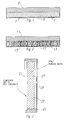
- FIGURE 3 An example of a PCM substrate/module is shown in FIGURE 3.
- An enclosure is formed using a plate of aluminum 21 secured to a wall member 23 which can be of any material capable of withstanding the conditions to which the module will be subjected, such as a plastic.
- the porous medium 25 is placed in the cavity formed by the wall 23 and plate 21 and the PCM material 27 in liquid form is then poured into the cavity and the lid 29 is then secured to the wall 23 to enclose the porous medium and PCM material within the cavity.
- Components, circuit boards or other heat generators are then secured to the plate 21 for extraction of the heat therefrom and conduction of this heat to the PCM material 27 via the porous medium 25.
Landscapes
- Engineering & Computer Science (AREA)
- Physics & Mathematics (AREA)
- Computer Hardware Design (AREA)
- Condensed Matter Physics & Semiconductors (AREA)
- General Physics & Mathematics (AREA)
- Microelectronics & Electronic Packaging (AREA)
- Power Engineering (AREA)
- Materials Engineering (AREA)
- Chemical & Material Sciences (AREA)
- Thermal Sciences (AREA)
- Mechanical Engineering (AREA)
- General Engineering & Computer Science (AREA)
- Cooling Or The Like Of Semiconductors Or Solid State Devices (AREA)
- Manufacture Of Alloys Or Alloy Compounds (AREA)
Applications Claiming Priority (2)
| Application Number | Priority Date | Filing Date | Title |
|---|---|---|---|
| US40622695A | 1995-03-17 | 1995-03-17 | |
| US406226 | 1995-03-17 |
Publications (2)
| Publication Number | Publication Date |
|---|---|
| EP0732743A2 true EP0732743A2 (fr) | 1996-09-18 |
| EP0732743A3 EP0732743A3 (fr) | 1998-05-13 |
Family
ID=23607071
Family Applications (1)
| Application Number | Title | Priority Date | Filing Date |
|---|---|---|---|
| EP96301801A Withdrawn EP0732743A3 (fr) | 1995-03-17 | 1996-03-15 | Dissipateurs de chaleur |
Country Status (2)
| Country | Link |
|---|---|
| US (1) | US6959753B1 (fr) |
| EP (1) | EP0732743A3 (fr) |
Cited By (17)
| Publication number | Priority date | Publication date | Assignee | Title |
|---|---|---|---|---|
| EP0989795A2 (fr) * | 1998-09-24 | 2000-03-29 | Sun Microsystems, Inc. | Système de réfrigération de composants électroniques |
| WO2000054332A1 (fr) * | 1999-03-11 | 2000-09-14 | Conexant Systems, Inc | Systeme de refroidissement pour electronique pulsee en puissance |
| WO2001004950A1 (fr) * | 1999-07-12 | 2001-01-18 | Siemens Aktiengesellschaft | Dispositif pour la dissipation thermique de composants semi-conducteurs en cas d'apparition de pointes de charge |
| US6181558B1 (en) * | 1999-08-24 | 2001-01-30 | Cairns Advanced Tech. Inc. | Heat absorber and combination electrical apparatus producing heat and heat absorber |
| US6276159B1 (en) | 1995-09-20 | 2001-08-21 | Sun Microsystems, Inc. | Sorption refrigeration appliance |
| EP1162659A2 (fr) * | 2000-06-08 | 2001-12-12 | MERCK PATENT GmbH | Utilisation de PCM dans les dissipateurs de chaleur pour dispositifs électroniques |
| US6349553B1 (en) | 1995-09-20 | 2002-02-26 | Sun Microsystems, Inc. | Method and system for cooling electrical components |
| US6415626B1 (en) | 1995-09-20 | 2002-07-09 | Sun Microsystems, Inc. | Sorber having flexible housing |
| WO2002059965A1 (fr) * | 2001-01-22 | 2002-08-01 | Parker Hannifin Corporation | Interface thermique a changement de phase et a elimination propre de couche |
| WO2004109798A1 (fr) * | 2003-05-22 | 2004-12-16 | Siemens Aktiengesellschaft | Procede et systeme de protection thermique d'unites electroniques dans un appareil electronique |
| DE10347518A1 (de) * | 2003-10-13 | 2005-05-25 | Siemens Ag | Elektronisches Bauelement, Schaltungsträgeraufbau und Elektronikeinheit mit Wärmespeicher |
| DE102004021810A1 (de) * | 2004-05-03 | 2005-12-01 | Conti Temic Microelectronic Gmbh | Elektronisches Bauelement sowie Verfahren zur Herstellung eines elektronischen Bauelementes |
| GB2462620A (en) * | 2008-08-13 | 2010-02-17 | Bae Systems Plc | Latent heat storage body comprising a thermally conductive structure |
| EP3048408A1 (fr) * | 2015-01-15 | 2016-07-27 | Hamilton Sundstrand Space Systems International, Inc. | Système de dissipateur de chaleur passif composite et procédé |
| CN105990509A (zh) * | 2015-02-02 | 2016-10-05 | 明安国际企业股份有限公司 | 高导热发光二极体 |
| US20170127557A1 (en) * | 2015-10-28 | 2017-05-04 | Raytheon Company | Phase change material heat sink using additive manufacturing and method |
| EP3240372A1 (fr) | 2016-04-27 | 2017-11-01 | AT & S Austria Technologie & Systemtechnik Aktiengesellschaft | Support de composant capacitif de chaleur et procédé pour produire ce composant support |
Families Citing this family (19)
| Publication number | Priority date | Publication date | Assignee | Title |
|---|---|---|---|---|
| US20050280987A1 (en) * | 2004-06-07 | 2005-12-22 | Kwitek Benjamin J | Phase change materials as a heat sink for computers |
| CA2767569C (fr) | 2009-07-10 | 2016-06-21 | Takao Kanemaru | Transducteur a cycle de stirling concu pour convertir l'energie thermique en energie mecanique et inversement |
| US20110044004A1 (en) * | 2009-08-18 | 2011-02-24 | Garosshen Thomas J | Heat transfer apparatus having a thermal interface material |
| FR2961894B1 (fr) * | 2010-06-24 | 2013-09-13 | Valeo Vision | Dispositif a echange de chaleur, notamment pour vehicule automobile |
| JP2014501868A (ja) | 2010-11-18 | 2014-01-23 | エタリム インコーポレイテッド | スターリングサイクル変換器装置 |
| WO2012157521A1 (fr) * | 2011-05-17 | 2012-11-22 | シャープ株式会社 | Dispositif de transfert de chaleur |
| US9293197B2 (en) | 2011-08-15 | 2016-03-22 | Lockheed Martin Corporation | Reconfigurable phase change material masks for electro-optical compressive sensing |
| JP2013115083A (ja) * | 2011-11-25 | 2013-06-10 | Fujitsu Semiconductor Ltd | 半導体装置及びその製造方法 |
| US9340446B1 (en) | 2013-02-04 | 2016-05-17 | Lockheed Martin Corporation | Optical apparatus and method of forming a gradient index device |
| WO2015023246A1 (fr) * | 2013-08-10 | 2015-02-19 | Intel Corporation | Stockage d'énergie thermique, dissipation et suppression d'emi pour des circuits intégrés utilisant des feuilles de graphite poreuses et un matériau à changement de phase |
| US10151542B2 (en) | 2014-04-03 | 2018-12-11 | Raytheon Company | Encapsulated phase change material heat sink and method |
| US10437083B1 (en) | 2014-10-20 | 2019-10-08 | Lockheed Martin Corporation | Individually addressable infrared mask array |
| JP6604721B2 (ja) * | 2014-12-26 | 2019-11-13 | 永大産業株式会社 | 耐熱性に優れた、潜熱蓄熱材含浸蓄熱体 |
| US20160209126A1 (en) * | 2015-01-15 | 2016-07-21 | Hamilton Sundstrand Space Systems International, Inc. | Composite flow-through heat sink system and method |
| US9969647B2 (en) | 2016-05-17 | 2018-05-15 | Lockheed Martin Energy, Llc | Glass composites having a gradient index of refraction and methods for production thereof |
| US9908808B1 (en) | 2016-08-18 | 2018-03-06 | Lockheed Martin Corporation | Ternary glass materials with low refractive index variability |
| US20180090415A1 (en) * | 2016-09-27 | 2018-03-29 | Hewlett Packard Enterprise Development Lp | Heat dissipating apparatuses with phase change materials |
| CN113490402B (zh) * | 2021-09-08 | 2021-11-02 | 凯瑞电子(诸城)有限公司 | 一种电子元件壳体封装结构 |
| CN114497813B (zh) * | 2022-03-31 | 2022-06-28 | 深圳市森若新材科技有限公司 | 相变复合膜及包括所述相变复合膜的电池和芯片组件 |
Citations (7)
| Publication number | Priority date | Publication date | Assignee | Title |
|---|---|---|---|---|
| US4047198A (en) * | 1976-04-19 | 1977-09-06 | Hughes Aircraft Company | Transistor cooling by heat pipes having a wick of dielectric powder |
| JPS63267890A (ja) * | 1986-12-11 | 1988-11-04 | Toray Ind Inc | 柔軟な熱伝達素子 |
| US4966226A (en) * | 1989-12-29 | 1990-10-30 | Digital Equipment Corporation | Composite graphite heat pipe apparatus and method |
| JPH0444352A (ja) * | 1990-06-12 | 1992-02-14 | Fujikura Ltd | ヒートパイプ式電子部品冷却器 |
| EP0541456A1 (fr) * | 1991-10-24 | 1993-05-12 | Transcal | Support de carte de composants électroniques à faible résistance thermique |
| US5325913A (en) * | 1993-06-25 | 1994-07-05 | The United States Of America As Represented By The Secretary Of The Navy | Module cooling system |
| JPH06291480A (ja) * | 1993-04-05 | 1994-10-18 | Mitsubishi Electric Corp | 電子回路モジュール |
Family Cites Families (28)
| Publication number | Priority date | Publication date | Assignee | Title |
|---|---|---|---|---|
| US2677367A (en) * | 1951-04-25 | 1954-05-04 | Telkes Maria | Heat storage unit |
| US3132688A (en) * | 1963-04-08 | 1964-05-12 | Welville B Nowak | Electronic cold and/or hot compress device |
| US4057101A (en) * | 1976-03-10 | 1977-11-08 | Westinghouse Electric Corporation | Heat sink |
| US4268558A (en) * | 1977-07-01 | 1981-05-19 | Boardman Energy Systems, Inc. | Thermal storage material and process for making |
| US4381818A (en) * | 1977-12-19 | 1983-05-03 | International Business Machines Corporation | Porous film heat transfer |
| US4178727A (en) * | 1978-02-01 | 1979-12-18 | Architectural Research Corporation | Heat absorbing panel |
| JPS5596892A (en) * | 1979-01-18 | 1980-07-23 | Hisaka Works Ltd | Heat transfer plate for plate type evaporator |
| US4341262A (en) * | 1980-05-05 | 1982-07-27 | Alspaugh Thomas R | Energy storage system and method |
| DE3038723A1 (de) * | 1980-10-14 | 1982-05-06 | L. & C. Steinmüller GmbH, 5270 Gummersbach | Waermespeichermasse fuer regenerativen waermeaustausch |
| US4512388A (en) * | 1981-06-19 | 1985-04-23 | Institute Of Gas Technology | High-temperature direct-contact thermal energy storage using phase-change media |
| US4446916A (en) * | 1981-08-13 | 1984-05-08 | Hayes Claude Q C | Heat-absorbing heat sink |
| US4528208A (en) * | 1983-10-13 | 1985-07-09 | Zymet, Inc. | Method and apparatus for controlling article temperature during treatment in vacuum |
| JPS60232496A (ja) * | 1984-05-04 | 1985-11-19 | Fujitsu Ltd | 熱交換器 |
| JP2569003B2 (ja) * | 1986-03-20 | 1997-01-08 | 株式会社日立製作所 | 熱伝導装置 |
| US4832118A (en) * | 1986-11-24 | 1989-05-23 | Sundstrand Corporation | Heat exchanger |
| JPH0716317B2 (ja) * | 1987-08-11 | 1995-02-22 | 株式会社テック | 電動送風機の入力制御回路 |
| JPH028497A (ja) * | 1988-06-15 | 1990-01-11 | Sumitomo Electric Ind Ltd | 管体埋設機における方向制御装置 |
| US4898234A (en) * | 1988-08-19 | 1990-02-06 | Mcdonnell Douglas Corporation | Air heat exchanger |
| US5007478A (en) * | 1989-05-26 | 1991-04-16 | University Of Miami | Microencapsulated phase change material slurry heat sinks |
| US5039577A (en) * | 1990-05-31 | 1991-08-13 | Hughes Aircraft Company | Hybrid metal matrix composite chassis structure for electronic circuits |
| US5123982A (en) * | 1990-06-29 | 1992-06-23 | The United States Of American As Represented By The United States Department Of Energy | Process of making cryogenically cooled high thermal performance crystal optics |
| JPH04143526A (ja) * | 1990-10-05 | 1992-05-18 | I N R Kenkyusho:Kk | 放熱、吸熱ラジエータ及びパネル |
| US5404272A (en) * | 1991-10-24 | 1995-04-04 | Transcal | Carrier for a card carrying electronic components and of low heat resistance |
| US5225964A (en) * | 1991-10-31 | 1993-07-06 | Rockwell International Corporation | Integrated lightweight card rack |
| JPH0634287A (ja) * | 1992-07-14 | 1994-02-08 | Matsushita Electric Works Ltd | 蓄熱ボード |
| US5267611A (en) * | 1993-01-08 | 1993-12-07 | Thermacore, Inc. | Single phase porous layer heat exchanger |
| US5390734A (en) * | 1993-05-28 | 1995-02-21 | Lytron Incorporated | Heat sink |
| US5852548A (en) * | 1994-09-09 | 1998-12-22 | Northrop Grumman Corporation | Enhanced heat transfer in printed circuit boards and electronic components thereof |
-
1996
- 1996-03-15 EP EP96301801A patent/EP0732743A3/fr not_active Withdrawn
- 1996-07-01 US US08/675,280 patent/US6959753B1/en not_active Expired - Lifetime
Patent Citations (7)
| Publication number | Priority date | Publication date | Assignee | Title |
|---|---|---|---|---|
| US4047198A (en) * | 1976-04-19 | 1977-09-06 | Hughes Aircraft Company | Transistor cooling by heat pipes having a wick of dielectric powder |
| JPS63267890A (ja) * | 1986-12-11 | 1988-11-04 | Toray Ind Inc | 柔軟な熱伝達素子 |
| US4966226A (en) * | 1989-12-29 | 1990-10-30 | Digital Equipment Corporation | Composite graphite heat pipe apparatus and method |
| JPH0444352A (ja) * | 1990-06-12 | 1992-02-14 | Fujikura Ltd | ヒートパイプ式電子部品冷却器 |
| EP0541456A1 (fr) * | 1991-10-24 | 1993-05-12 | Transcal | Support de carte de composants électroniques à faible résistance thermique |
| JPH06291480A (ja) * | 1993-04-05 | 1994-10-18 | Mitsubishi Electric Corp | 電子回路モジュール |
| US5325913A (en) * | 1993-06-25 | 1994-07-05 | The United States Of America As Represented By The Secretary Of The Navy | Module cooling system |
Non-Patent Citations (4)
| Title |
|---|
| "MELTING WAX COOLS HOT COMPONENTS" 10 October 1985 , MACHINE DESIGN, VOL. 57, NR. 23, PAGE(S) 48 XP000579938 * the whole document * * |
| PATENT ABSTRACTS OF JAPAN vol. 013, no. 065 (M-797), 14 February 1989 -& JP 63 267890 A (TORAY IND INC), 4 November 1988, * |
| PATENT ABSTRACTS OF JAPAN vol. 016, no. 230 (E-1208), 27 May 1992 -& JP 04 044352 A (FUJIKURA LTD;OTHERS: 01), 14 February 1992, * |
| PATENT ABSTRACTS OF JAPAN vol. 095, no. 001, 28 February 1995 -& JP 06 291480 A (MITSUBISHI ELECTRIC CORP), 18 October 1994, * |
Cited By (29)
| Publication number | Priority date | Publication date | Assignee | Title |
|---|---|---|---|---|
| US6349553B1 (en) | 1995-09-20 | 2002-02-26 | Sun Microsystems, Inc. | Method and system for cooling electrical components |
| US6497110B2 (en) | 1995-09-20 | 2002-12-24 | Sun Microsystems, Inc. | Refrigeration system for electronic components having environmental isolation |
| US6276159B1 (en) | 1995-09-20 | 2001-08-21 | Sun Microsystems, Inc. | Sorption refrigeration appliance |
| US6279337B1 (en) | 1995-09-20 | 2001-08-28 | Sun Microsystems, Inc. | Refrigeration system for electronic components having environmental isolation |
| US6415626B1 (en) | 1995-09-20 | 2002-07-09 | Sun Microsystems, Inc. | Sorber having flexible housing |
| EP0989795A3 (fr) * | 1998-09-24 | 2000-12-27 | Sun Microsystems, Inc. | Système de réfrigération de composants électroniques |
| EP0989795A2 (fr) * | 1998-09-24 | 2000-03-29 | Sun Microsystems, Inc. | Système de réfrigération de composants électroniques |
| WO2000054332A1 (fr) * | 1999-03-11 | 2000-09-14 | Conexant Systems, Inc | Systeme de refroidissement pour electronique pulsee en puissance |
| US6848500B1 (en) | 1999-03-11 | 2005-02-01 | Skyworks Solutions, Inc. | Cooling system for pulsed power electronics |
| DE19932441A1 (de) * | 1999-07-12 | 2001-01-25 | Siemens Ag | Vorrichtung zur Entwärmung von Halbleiterbauelementen beim Auftreten von Belastungsspitzen |
| WO2001004950A1 (fr) * | 1999-07-12 | 2001-01-18 | Siemens Aktiengesellschaft | Dispositif pour la dissipation thermique de composants semi-conducteurs en cas d'apparition de pointes de charge |
| US6181558B1 (en) * | 1999-08-24 | 2001-01-30 | Cairns Advanced Tech. Inc. | Heat absorber and combination electrical apparatus producing heat and heat absorber |
| EP1162659A2 (fr) * | 2000-06-08 | 2001-12-12 | MERCK PATENT GmbH | Utilisation de PCM dans les dissipateurs de chaleur pour dispositifs électroniques |
| EP1162659A3 (fr) * | 2000-06-08 | 2005-02-16 | MERCK PATENT GmbH | Utilisation de PCM dans les dissipateurs de chaleur pour dispositifs électroniques |
| WO2002059965A1 (fr) * | 2001-01-22 | 2002-08-01 | Parker Hannifin Corporation | Interface thermique a changement de phase et a elimination propre de couche |
| US6835453B2 (en) | 2001-01-22 | 2004-12-28 | Parker-Hannifin Corporation | Clean release, phase change thermal interface |
| DE10324156A1 (de) * | 2003-05-22 | 2004-12-16 | Siemens Ag | Verfahren und Anordnung zum thermischen Schutz elektronischer Einheiten in einem elektronischen Gerät |
| WO2004109798A1 (fr) * | 2003-05-22 | 2004-12-16 | Siemens Aktiengesellschaft | Procede et systeme de protection thermique d'unites electroniques dans un appareil electronique |
| DE10347518A1 (de) * | 2003-10-13 | 2005-05-25 | Siemens Ag | Elektronisches Bauelement, Schaltungsträgeraufbau und Elektronikeinheit mit Wärmespeicher |
| DE102004021810A1 (de) * | 2004-05-03 | 2005-12-01 | Conti Temic Microelectronic Gmbh | Elektronisches Bauelement sowie Verfahren zur Herstellung eines elektronischen Bauelementes |
| GB2462620A (en) * | 2008-08-13 | 2010-02-17 | Bae Systems Plc | Latent heat storage body comprising a thermally conductive structure |
| EP3048408A1 (fr) * | 2015-01-15 | 2016-07-27 | Hamilton Sundstrand Space Systems International, Inc. | Système de dissipateur de chaleur passif composite et procédé |
| CN105990509A (zh) * | 2015-02-02 | 2016-10-05 | 明安国际企业股份有限公司 | 高导热发光二极体 |
| US20170127557A1 (en) * | 2015-10-28 | 2017-05-04 | Raytheon Company | Phase change material heat sink using additive manufacturing and method |
| US10123456B2 (en) * | 2015-10-28 | 2018-11-06 | Raytheon Company | Phase change material heat sink using additive manufacturing and method |
| EP3240372A1 (fr) | 2016-04-27 | 2017-11-01 | AT & S Austria Technologie & Systemtechnik Aktiengesellschaft | Support de composant capacitif de chaleur et procédé pour produire ce composant support |
| WO2017186856A1 (fr) | 2016-04-27 | 2017-11-02 | At&S Austria Technologie & Systemtechnik Aktiengesellschaft | Support de composant capacitif thermique et procédé de production dudit support de composant |
| CN109417847A (zh) * | 2016-04-27 | 2019-03-01 | At&S奥地利科技与系统技术股份公司 | 储热部件载体及生产所述部件载体的方法 |
| US10945332B2 (en) | 2016-04-27 | 2021-03-09 | At&S Austria Technologie & Systemtechnik Aktiengesellschaft | Heat capacitive component carrier and method to produce said component carrier |
Also Published As
| Publication number | Publication date |
|---|---|
| US6959753B1 (en) | 2005-11-01 |
| EP0732743A3 (fr) | 1998-05-13 |
Similar Documents
| Publication | Publication Date | Title |
|---|---|---|
| EP0732743A2 (fr) | Dissipateurs de chaleur | |
| US6661664B2 (en) | Electronic module with high cooling power | |
| US4118756A (en) | Heat pipe thermal mounting plate for cooling electronic circuit cards | |
| CA2964864C (fr) | Dispositif de capacite thermique | |
| US7603775B2 (en) | Heat spreader with vapor chamber and method of manufacturing the same | |
| US7556086B2 (en) | Orientation-independent thermosyphon heat spreader | |
| EP0471552B1 (fr) | Module de transport de chaleur pour des applications à très haute densité et à empaquetage silicium sur silicium | |
| US5533257A (en) | Method for forming a heat dissipation apparatus | |
| US5283715A (en) | Integrated heat pipe and circuit board structure | |
| JPH11163237A (ja) | 複合ヒートシンク | |
| US8335083B2 (en) | Apparatus and method for thermal management using vapor chamber | |
| KR100468217B1 (ko) | 다공성 금속물질을 이용한 축방열 시스템 | |
| WO1996028846A1 (fr) | Dissipateur de chaleur | |
| JPH0645488A (ja) | Icチップの温度制御装置 | |
| US5831831A (en) | Bonding material and phase change material system for heat burst dissipation | |
| EP1676314A1 (fr) | Dissipateur thermique en mousse de graphite a densite variable | |
| US20090169410A1 (en) | Method of forming a thermo pyrolytic graphite-embedded heatsink | |
| US6481491B2 (en) | Cooling apparatus based on heat energy bound to working fluid in phase transition | |
| TW502102B (en) | Thermal transfer devices | |
| JPH10335863A (ja) | 制御装置 | |
| GB2462620A (en) | Latent heat storage body comprising a thermally conductive structure | |
| JP3403307B2 (ja) | ヒートスプレッダとそれを用いた冷却器 | |
| WO2001067019A1 (fr) | Dissipateur de chaleur sous forme de matrice contenant des fibres allongees | |
| Sarno et al. | Use of metal matrix composite material heat pipes for the thermal management of high integrated electronic packages | |
| EP0002558B1 (fr) | Superfuite et échangeur de chaleur |
Legal Events
| Date | Code | Title | Description |
|---|---|---|---|
| PUAI | Public reference made under article 153(3) epc to a published international application that has entered the european phase |
Free format text: ORIGINAL CODE: 0009012 |
|
| AK | Designated contracting states |
Kind code of ref document: A2 Designated state(s): DE FR GB IT NL |
|
| PUAL | Search report despatched |
Free format text: ORIGINAL CODE: 0009013 |
|
| AK | Designated contracting states |
Kind code of ref document: A3 Designated state(s): DE FR GB IT NL |
|
| STAA | Information on the status of an ep patent application or granted ep patent |
Free format text: STATUS: THE APPLICATION HAS BEEN WITHDRAWN |
|
| 17P | Request for examination filed |
Effective date: 19981103 |
|
| 18W | Application withdrawn |
Withdrawal date: 19981105 |