EP0732679A1 - Panneau d'affichage pour instrument d'un tableau de bord d'un véhicule - Google Patents
Panneau d'affichage pour instrument d'un tableau de bord d'un véhicule Download PDFInfo
- Publication number
- EP0732679A1 EP0732679A1 EP96301775A EP96301775A EP0732679A1 EP 0732679 A1 EP0732679 A1 EP 0732679A1 EP 96301775 A EP96301775 A EP 96301775A EP 96301775 A EP96301775 A EP 96301775A EP 0732679 A1 EP0732679 A1 EP 0732679A1
- Authority
- EP
- European Patent Office
- Prior art keywords
- light guide
- light
- display panel
- scattering
- light source
- Prior art date
- Legal status (The legal status is an assumption and is not a legal conclusion. Google has not performed a legal analysis and makes no representation as to the accuracy of the status listed.)
- Withdrawn
Links
Images


Classifications
-
- G—PHYSICS
- G02—OPTICS
- G02B—OPTICAL ELEMENTS, SYSTEMS OR APPARATUS
- G02B6/00—Light guides; Structural details of arrangements comprising light guides and other optical elements, e.g. couplings
- G02B6/0001—Light guides; Structural details of arrangements comprising light guides and other optical elements, e.g. couplings specially adapted for lighting devices or systems
- G02B6/0011—Light guides; Structural details of arrangements comprising light guides and other optical elements, e.g. couplings specially adapted for lighting devices or systems the light guides being planar or of plate-like form
- G02B6/0013—Means for improving the coupling-in of light from the light source into the light guide
- G02B6/0015—Means for improving the coupling-in of light from the light source into the light guide provided on the surface of the light guide or in the bulk of it
- G02B6/002—Means for improving the coupling-in of light from the light source into the light guide provided on the surface of the light guide or in the bulk of it by shaping at least a portion of the light guide, e.g. with collimating, focussing or diverging surfaces
- G02B6/0021—Means for improving the coupling-in of light from the light source into the light guide provided on the surface of the light guide or in the bulk of it by shaping at least a portion of the light guide, e.g. with collimating, focussing or diverging surfaces for housing at least a part of the light source, e.g. by forming holes or recesses
-
- B—PERFORMING OPERATIONS; TRANSPORTING
- B60—VEHICLES IN GENERAL
- B60K—ARRANGEMENT OR MOUNTING OF PROPULSION UNITS OR OF TRANSMISSIONS IN VEHICLES; ARRANGEMENT OR MOUNTING OF PLURAL DIVERSE PRIME-MOVERS IN VEHICLES; AUXILIARY DRIVES FOR VEHICLES; INSTRUMENTATION OR DASHBOARDS FOR VEHICLES; ARRANGEMENTS IN CONNECTION WITH COOLING, AIR INTAKE, GAS EXHAUST OR FUEL SUPPLY OF PROPULSION UNITS IN VEHICLES
- B60K35/00—Arrangement of adaptations of instruments
-
- B—PERFORMING OPERATIONS; TRANSPORTING
- B60—VEHICLES IN GENERAL
- B60Q—ARRANGEMENT OF SIGNALLING OR LIGHTING DEVICES, THE MOUNTING OR SUPPORTING THEREOF OR CIRCUITS THEREFOR, FOR VEHICLES IN GENERAL
- B60Q3/00—Arrangement of lighting devices for vehicle interiors; Lighting devices specially adapted for vehicle interiors
- B60Q3/10—Arrangement of lighting devices for vehicle interiors; Lighting devices specially adapted for vehicle interiors for dashboards
- B60Q3/14—Arrangement of lighting devices for vehicle interiors; Lighting devices specially adapted for vehicle interiors for dashboards lighting through the surface to be illuminated
-
- B—PERFORMING OPERATIONS; TRANSPORTING
- B60—VEHICLES IN GENERAL
- B60Q—ARRANGEMENT OF SIGNALLING OR LIGHTING DEVICES, THE MOUNTING OR SUPPORTING THEREOF OR CIRCUITS THEREFOR, FOR VEHICLES IN GENERAL
- B60Q3/00—Arrangement of lighting devices for vehicle interiors; Lighting devices specially adapted for vehicle interiors
- B60Q3/60—Arrangement of lighting devices for vehicle interiors; Lighting devices specially adapted for vehicle interiors characterised by optical aspects
- B60Q3/62—Arrangement of lighting devices for vehicle interiors; Lighting devices specially adapted for vehicle interiors characterised by optical aspects using light guides
- B60Q3/64—Arrangement of lighting devices for vehicle interiors; Lighting devices specially adapted for vehicle interiors characterised by optical aspects using light guides for a single lighting device
-
- G—PHYSICS
- G01—MEASURING; TESTING
- G01D—MEASURING NOT SPECIALLY ADAPTED FOR A SPECIFIC VARIABLE; ARRANGEMENTS FOR MEASURING TWO OR MORE VARIABLES NOT COVERED IN A SINGLE OTHER SUBCLASS; TARIFF METERING APPARATUS; MEASURING OR TESTING NOT OTHERWISE PROVIDED FOR
- G01D11/00—Component parts of measuring arrangements not specially adapted for a specific variable
- G01D11/28—Structurally-combined illuminating devices
-
- G—PHYSICS
- G02—OPTICS
- G02B—OPTICAL ELEMENTS, SYSTEMS OR APPARATUS
- G02B6/00—Light guides; Structural details of arrangements comprising light guides and other optical elements, e.g. couplings
- G02B6/0001—Light guides; Structural details of arrangements comprising light guides and other optical elements, e.g. couplings specially adapted for lighting devices or systems
- G02B6/0011—Light guides; Structural details of arrangements comprising light guides and other optical elements, e.g. couplings specially adapted for lighting devices or systems the light guides being planar or of plate-like form
- G02B6/0013—Means for improving the coupling-in of light from the light source into the light guide
- G02B6/0015—Means for improving the coupling-in of light from the light source into the light guide provided on the surface of the light guide or in the bulk of it
- G02B6/0016—Grooves, prisms, gratings, scattering particles or rough surfaces
-
- G—PHYSICS
- G02—OPTICS
- G02B—OPTICAL ELEMENTS, SYSTEMS OR APPARATUS
- G02B6/00—Light guides; Structural details of arrangements comprising light guides and other optical elements, e.g. couplings
- G02B6/0001—Light guides; Structural details of arrangements comprising light guides and other optical elements, e.g. couplings specially adapted for lighting devices or systems
- G02B6/0011—Light guides; Structural details of arrangements comprising light guides and other optical elements, e.g. couplings specially adapted for lighting devices or systems the light guides being planar or of plate-like form
- G02B6/0033—Means for improving the coupling-out of light from the light guide
- G02B6/0035—Means for improving the coupling-out of light from the light guide provided on the surface of the light guide or in the bulk of it
- G02B6/0038—Linear indentations or grooves, e.g. arc-shaped grooves or meandering grooves, extending over the full length or width of the light guide
-
- G—PHYSICS
- G02—OPTICS
- G02B—OPTICAL ELEMENTS, SYSTEMS OR APPARATUS
- G02B6/00—Light guides; Structural details of arrangements comprising light guides and other optical elements, e.g. couplings
- G02B6/0001—Light guides; Structural details of arrangements comprising light guides and other optical elements, e.g. couplings specially adapted for lighting devices or systems
- G02B6/0011—Light guides; Structural details of arrangements comprising light guides and other optical elements, e.g. couplings specially adapted for lighting devices or systems the light guides being planar or of plate-like form
- G02B6/0066—Light guides; Structural details of arrangements comprising light guides and other optical elements, e.g. couplings specially adapted for lighting devices or systems the light guides being planar or of plate-like form characterised by the light source being coupled to the light guide
- G02B6/0068—Arrangements of plural sources, e.g. multi-colour light sources
-
- G—PHYSICS
- G02—OPTICS
- G02B—OPTICAL ELEMENTS, SYSTEMS OR APPARATUS
- G02B6/00—Light guides; Structural details of arrangements comprising light guides and other optical elements, e.g. couplings
- G02B6/0001—Light guides; Structural details of arrangements comprising light guides and other optical elements, e.g. couplings specially adapted for lighting devices or systems
- G02B6/0011—Light guides; Structural details of arrangements comprising light guides and other optical elements, e.g. couplings specially adapted for lighting devices or systems the light guides being planar or of plate-like form
- G02B6/0033—Means for improving the coupling-out of light from the light guide
- G02B6/0035—Means for improving the coupling-out of light from the light guide provided on the surface of the light guide or in the bulk of it
- G02B6/0045—Means for improving the coupling-out of light from the light guide provided on the surface of the light guide or in the bulk of it by shaping at least a portion of the light guide
- G02B6/0046—Tapered light guide, e.g. wedge-shaped light guide
-
- G—PHYSICS
- G02—OPTICS
- G02B—OPTICAL ELEMENTS, SYSTEMS OR APPARATUS
- G02B6/00—Light guides; Structural details of arrangements comprising light guides and other optical elements, e.g. couplings
- G02B6/0001—Light guides; Structural details of arrangements comprising light guides and other optical elements, e.g. couplings specially adapted for lighting devices or systems
- G02B6/0011—Light guides; Structural details of arrangements comprising light guides and other optical elements, e.g. couplings specially adapted for lighting devices or systems the light guides being planar or of plate-like form
- G02B6/0033—Means for improving the coupling-out of light from the light guide
- G02B6/0058—Means for improving the coupling-out of light from the light guide varying in density, size, shape or depth along the light guide
- G02B6/006—Means for improving the coupling-out of light from the light guide varying in density, size, shape or depth along the light guide to produce indicia, symbols, texts or the like
Definitions
- the present invention relates to a display panel for instruments installed in vehicles such as motor cars, airplanes, ships etc., or for the other devices similar to them, more particularly, relates to a display panel provided with a back light for illuminating display information from the back side thereof.
- instruments various kinds of instruments installed in vehicles and other devices similar to them are referred to as "instruments" for a general name in this specification.
- a display device for displaying various kinds of information such as a speed meter, a navigation system, an altimeter, an operation panel of an air conditioner, a tuning operation portion of a radio, etc.
- a back light illumination mechanism for facilitating the perception of display at night, in a tunnel, etc., is built in the display panel for use in those instruments.
- the construction and the characteristics of conventional illumination mechanisms are described with examples of a speed meter and an operating portion of the air conditioner.
- FIGs. 1 to 3 there are illustrated a schematic construction of a conventional display panel of a speed meter.
- Fig. 1 shows an external appearance viewing from the front side (observing side) together with a light source element and
- Fig. 2 shows an external appearance viewing from the back side (light incident side) in an element-exploded manner.
- Fig. 3a and Fig. 3b are sectional views taken along the line DD' and the line EE' in Fig. 2, respectively.
- a display panel of a speed meter represented as a whole by reference numeral 10 is constituted of a plate shape transparent light guide 11 made of an acryl resin, etc., two light source elements (incandescent lamp) L arranged at the back side of the transparent light guide 11, a diffusing sheet 12 arranged so as to overlap on the front side surface of the transparent light guide 11, a masking 14 having notch parts corresponding to shining parts 13, and a pointer 16 turning around a rotation shaft 15.
- the illustration of a rotation mechanism of the pointer 16 is omitted.
- the masking 14 is usually made of a light shielding ink layer which is printed on the diffusing sheet 12.
- the shape of notch parts of the masking 14 which form the shining part 13 are defined according to the display contents of speed scale marks, numerals, and letters, etc.
- a transparent ink layer having a desired color is printed on the diffusing sheet 12 corresponding to this notch part.
- Stipples 11C for guiding light to the front side based on edge lighting effect are formed on the surface of the transparent light guide 11 distant from the light source element L. As illustrated in Fig. 3a, a part of the light (represented as G1, G2) entering obliquely into the stipples 11C travels from the stipples 11C to the diffusing sheet 12. A scattered display light G3 is generated at the shining part 13 on which the masking 14 does not exist.
- backward projecting parts 11A, 11B are disposed on left and right end portions of the transparent light guide 11 near the light source elements L, L.
- a strong light G4 is guided to the backward projecting part 11A (or 11B) with internal reflections repeated and then guided to a flat plate part of the transparent light guide 11.
- An attenuation print 12A for preventing the shining part 13 from becoming too bright locally is formed on a back surface part of the diffusing sheet 12 in the vicinity of the backward projecting parts 11A, 11B.
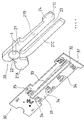
- Fig. 4 is a schematic element-exploded view of the construction of display panel of the operating portion of a conventional air conditioner.
- the display panel is constituted of a back light illuminating portion 20 and a main body 30 arranged so as to contact closely to the front side surface of the back light illuminating portion 20.
- the back light illuminating portion 20 includes a light source element (incandescent lamp) L and a transparent light guide 21 made of an acrylic resin.
- the transparent light guide 21 has a base part 21A and extending parts 21B, 21C.
- a wide part 21D is disposed on a leading end of the extending part 21B.
- a U-shape space 23 between both of the extending parts 21B, 21C aims to let an operating lever (not shown) pass movably in the lateral direction.
- a hole 22 for receiving a light emitting part of the light source element L disposed on the base part 21A.
- Stipples 24 for transforming the light guided in the transparent light guide due to edge lighting effect into a back light illuminating light is disposed on the wide part 21D positioned at a portion distant from the light source element L.
- a scattering sheet 31 is used as a base plate of the main body 30.
- a masking 33 made of a light shielding ink layer is formed on a surface of the scattering sheet 31 except the portion which forms a shining part 34.
- the shining part 34 may include desired letters such as HEAT, VENT, etc.
- Reference numeral 32 denotes a long and narrow opening disposed so as to be juxtaposed with the space 23 between the extending parts of the transparent light guide, through which the operating lever (not shown) is disposed movably in the lateral direction.
- a printing having an appropriate light shielding function is realized on an back surface part 35 of the scattering sheet 31 in the vicinity of the light source element L.
- the greater part of the light from the light source element L enters into the transparent light guide 21 from a peripheral portion of the hole 22 and is guided to the base part 21A, the extending parts 21B, 21C and the wide part 21D accompanied with the internal reflection. In this process, the light is guided toward a front surface of the main body 30 due to the function of the scattering sheet 31 and the stipples formed on the wide part 21D of the main body 30.
- An embodiment of the present invention may realise a compact and thin construction in a display panel of instruments installed in vehicles. It may also provide an electric power saving type display panel which facilitates ensuring of the quantity of light which contributes to the displaying and which is adapted to use small-sized and electric power saving source elements.
- a display panel for an instrument in which a shining part for displaying information is formed by using a primary light source means and a plate-shape light guide optically coupled to said primary light source means, wherein at least a part of the light guide is constituted by a scattering light guide which has a region tending to reduce in thickness as distance increases away from the position at which the optical coupling occurs, and at least a portion of the shining part is provided by light exiting from said region.
- the optical coupling with a primary light source may occur in a hole or recess disposed in the scattering light guide.
- the optical coupling may occur by disposing a sideward reflecting part for deflecting the light to an extending direction of the scattering light guide in the hole or recess.
- the optical coupling may occur at an edge part of the scattering light guide.
- a cut part may be disposed on the edge part.
- a light emitting diode for generating an incident light flux coordinately directed to the scattering light guide is adopted as the primary light source means.
- At least a part of the portion which does not correspond to the shining part may be coated with a layer having a refractive index lower than that of the scattering light guide.
- the basic characteristics of the display panel according to the present invention reside in that the scattering light guide having a region having a tendency of reducing in thickness corresponding to the distance from the part at which the light-coupling occurs is used as a means for transforming the light emitted from the primary light source into the displaying light.
- the scattering light guide having a region having a tendency of reducing in thickness corresponding to the distance from the part at which the light-coupling occurs is used as a means for transforming the light emitted from the primary light source into the displaying light.
- a taper shape or wedge shape is given to the peripheral portion.
- a taper shape or wedge shape is given to a center portion or its peripheral region.
- the layer having the refractive index lower than that of the scattering light guide is coated onto at least the part of the portion which does not correspond to the shining part as means for preventing the light which does not contribute to the displaying from exiting from the scattering light guide.
- the high refractive index medium scattering light guide
- the low refractive index medium coating layer
- a display panel according to the present invention is applied to the display panel of various kinds of the instruments installed in motorcars, airplanes, ships, etc., a thin construction which ensures the displaying light with a high efficiency is realized, through which the manufacturing cost and the consumption of electric power can be reduced. Further, since the scattered exiting light from the scattering light guide is used as the displaying light, "soft displaying light" can be obtained without additional constructions such as light diffusing sheet, and so on.
- a display panel of a speed meter specified by as a whole reference numeral 10 is constituted of a scattering light guide 50, three light source elements (LED, small-sized incandescent lamp, etc.) La - Lc, a transparent sheet 60 arranged so as to overlap on the front side surface of the scattering light guide 50 and a pointer 16 turning around a rotation axis 15.
- a masking 14 disposed on the front side surface of the transparent sheet 60 and the shining parts 13 corresponding to the notch parts of the transparent sheet 60 are shown by only the reference numerals thereof.
- the masking 14 is arranged in a similar manner to that of Fig. 1 except that the masking 14 is printed on the transparent sheet 60.
- a shape of the notch parts of the masking 14 which forms the shining part 13 is defined according to the display contents such as speed scales, numerals, letters, etc.
- the transparent sheet 60 may be made of a colorless transparent sheet or a colored transparent sheet.
- a transparent ink layer with a desired color may be printed on a portion corresponding to the notch portion of the masking 14.
- the scattering light guide 50 shaped into a disk having an axis K corresponding to the rotation shaft 15 is constituted of a center portion 51 having a uniform thickness and a periphery portion 52 shaped in a taper having a tendency of reducing in thickness in the radial direction.
- the respective light source receiving holes 53a - 53c receive small-sized light source elements La, Lb and Lc.
- Reference numeral 57 denotes stipples formed by a blast processing on a part of the back side surface of the center portion 51. This stipples 57 are disposed appropriately in a case where not only a peripheral portion of the display panel but also a portion in the vicinity of the center portion, etc. are required to provide a shining part 13 (Refer to "km/h" in Fig. 1).
- the scattering light guide 50 is made of a material having a refractive index ununiform structure in which different refractive index particles are distributed uniformly in the transparent matrix.
- the representative light in this path enters into the front side surface of the scattering light guide 50 at a relatively small angle after it reflects at the inclination surface. If this inclination angle is less than the critical angle (about 42° in a case where PMMA matrix is used), a part of the light corresponding thereto exits as an illuminating light H1' from the scattering light guide 50. Even if it is not less than the critical angle at the first entrance, a smaller incident angle will be obtained at the time of the second or the subsequent entrance, so that there is a high probability that the light exits from the scattering light guide 50 as the illuminating light H1'.
- the critical angle about 42° in a case where PMMA matrix is used
- the representative light in this path enters into the front side surface of the scattering light guide 50 at a relatively large angle, wherein there is a high probability that the total reflection is realized.
- the greater part of the light reflected totally enters again into the front side surface of the scattering light guide 50 after it reflects at the inclination surface of the periphery portion 52. Since the incident angle at this time is less than the last incident angle, similarly to the case of the light beam H1, there is a high probability that the escaping condition is satisfied and then the light corresponding thereto exits from the scattering light guide 50 as the illuminating lights H2', H3'.
- the smaller incident angle is obtained at the time of the second (or subsequent) entrance, so that there is a high probability that the light exits from the scattering light guide 50 as the illuminating light. [H4; the light which exits from the reflecting light source element Lc or the other light source element, and enters into the stipples 57]
- the greater part of the respective light in this path is changed in direction greatly at the stipples 57 and is directed to the front side surface of the scattering light guide 50, entering thereinto at a small incident angle not greater than the critical angle. Accordingly, there is a high probability that the escaping condition is satisfied, so that the light corresponding thereto exits from the scattering light guide 50 as the illumination lights H2', H3'.
- the scattering in the scattering light guide 50 is taken account into consideration.
- the scattering in the scattering light guide 50 is taken account into consideration, the light with a diffusing angle to some extent in the propagating directions of the respective light beams should be considered.
- the scattering power caused by the fine refractive index ununiform structure (different refractive index particles in this embodiment) distributed in the scattering light guide 50 shows basically a forward scattering.
- the size (the diameter of particles having different refractive indexes) of individual refractive index ununiform structure becomes small (for example, not greater than 0.01 ⁇ m), a tendency of reducing in the degree forward scattering grows.
- the light from the light sources La - Lc may not be sent up to the peripheral portion 52 sufficiently.
- the density and the size of the refractive index ununiform structures distributed in the scattering light guide 50 are adjusted in such a manner that the light exiting from the light source elements La - Lb are sent sufficiently to the peripheral portion 52.
- the density of the refractive index ununiform structures is adjusted according to the addition rate of the different refractive index particles.
- Tables 1 and 2 show some preferable examples of materials employed as polymer matrix of the scattering light guide 50 used in display panels of speed meters of a usual size. As different refractive index particles, silicone type micro particles, for example, are available. Table 1 Category Name of Polymer Refractive Index MA 1. PMMA [polymethyl methacrylate] 1.49 2. PEMA [polyethyl methacrylate] 1.483 3. Poly(nPMA) [poly-n-propyl methacrylate] 1.484 4.
- Poly(1-PhEMA) [poly-1-phenylethyl methacrylate] 1.543 13.
- Poly(2-PhEMA) [poly-2-phenylethyl methacrylate] 1.559 14.
- PFFMA polyfurfuryl methacrylate] 1.538 A 15.
- PMA polymethyl acrylate] 1.4725 16.
- PEA polyethyl acrylate] 1.4685 17.
- Poly(nBA) [poly-n-butyl acrylate] 1.4535 XA 18.
- PBzMA [polybenzyl acrylate] 1.5584 19.
- Poly(2-CIEA) [poly-2-chloroethyl acrylate] 1.52 Table 2 Category Name of Polymer Refractive Index AC 20.
- PVAc Polyvinyl acetate] 1.47 XA 21. PVB [polyvinyl benzoate] 1.578 22. PVAc [polyvinyl phenyl acetate] 1.567 23. PVClAc [polyvinyl chloroacetate] 1.512 N 24. PAN [polyacrylonitrile] 1.52 25. Poly( ⁇ MAN) [poly- ⁇ -methyl acrylonitrile] 1.52 ⁇ -A 26. PMA(2Cl) [polymethyl- ⁇ -chloroacrylate] 1.5172 St 27. Poly(o-C1St) [poly-o-chlorostyrene] 1.6098 28.
- Poly-(p-FSt) [poly-p-fluorostyrene] 1.566 29.
- Poly(o, p-FSt) [poly-o-, p-difluorostyrene] 1.475 30.
- Poly(p-iPSt) [poly-p-isopropyl styrene] 1.554 31.
- PSt [polystyrene] 1.59 C 32.
- a shining part 56 is formed at the front side of the peripheral portion 52 of the scattering light guide 50 when the light source elements La - Lc are turned on, as shown in Fig. 6.
- a shining part 57' is formed also on the back side of the center portion 51 on which the stipples 57 is formed. Only a little quantity of light leaks from the other part.
- the following means may be adopted for the optical coupling regions of both of them.
- the constructions and the reference numerals in the first embodiment are cited as required.
- Fig. 8 is a view to explain one example to which this means is applied in such a manner that the light source elements are arranged outside the holes 53a - 53c. Since respective holes 53a - 53c are equivalent in construction and function with each other, only the hole 53a and the light source element La for supplying the light to the hole 53a are shown in Fig. 8.
- a sideward reflecting part 53a' of the scattering light guide 50 formed as a conical projection is disposed inside the hole 53a, and the light source element La is arranged coaxially outside the hole 53a.
- the greater part FL1 of the light flux radiated from the light source element La is reflected at the surface of the sideward reflecting part 53a' inside the hole 53a, then transformed to the light flux FL4 travelling toward all around radial directions. Since the light flux FL4 enters into the cylindrical inner wall of the hole 53a substantially vertically thereto, it is introduced into the scattering light guide 50 with a high efficiency.
- the light source element La may be an incandescence lamp (bulb), LED, or the like.
- the light source element having a radial directivity is used in order to make efficient use of the sideward reflecting part 53a'.
- LEDs having a radial directivity are known.
- the light source element received in the receiving hole is devised to cause the sideward radial directivity.
- Fig. 9 is a view to explain an example in which this means is applied to an arrangement for receiving light emitting diodes (LEDs) in the holes 53a - 53c. Since respective holes 53a - 53c are equivalent in construction and function with each other, only the hole 53a and the light source element LEDa for supplying the light to the hole 53a are shown in Fig. 9.
- LEDs light emitting diodes
- the LEDa used in this embodiment is characterized by a cap part CP. That is, a conical recess shape sideward reflecting part RF is disposed on the cap part CP.
- the light fluxes FL1, FL1', FL1" radiated forward from a light emitting part EM of LEDa are reflected at the sideward reflecting part RF, then transformed to the light fluxes FL4 which are travelling toward all around radial directions. Since the reflection at the sideward reflecting part RF is caused by the entrance from the high refractive index material side, the greater part of the light can be totally reflected if the inclination of the sideward reflecting part RF is made large to some extent.
- the critical angle is about 40°. If the inclination of the sideward reflecting part RF is made larger than this angle, the light beam directed forward from the light emitting part EM is reflected totally at the sideward reflecting part RF. An inclination of about 45° is advantageous to introduce the light from the inner periphery walls of the receiving holes 53a - 53c into the scattering light guide 50.
- the inclination of the sideward reflecting part RF is made about 45° and the material of the cap has a refractive index equal or larger than that of the epoxy resin.
- the light is introduced efficiently into the scattering light guide along the extending direction of the scattering light guide. That is, the advantage exhibited in a case where the light source element is received inside the hole formed in the scattering light guide (i.e. the above-mentioned advantage 3) is made striking.
- the second and the third embodiments are described, in which the construction having an optical coupling part for a primary light source and a scattering light guide at the edge part of the scattering light guide is applied to a speed meter. Since these two embodiments and the first embodiment are different only in the optical coupling part for the scattering light guide and the primary light source, the illustration and the explanation for the other features are omitted.
- Fig. 10a is a view of the main part of the second embodiment viewing from the back side thereof and Fig. 10b is a view of the same viewing from the front side thereof.
- the scattering light guide 50 used in this embodiment comprises five elements 58a, 58b, 58c, 58d and 58e.
- the scattering light guide 50 may be produced by integral molding or assembling of the respective molded elements.
- the elements 58a, 58b, 58c and 58d are identical in size and construction, each of the elements having a corner CR, a uniform thickness part and a wedge part.
- reference numeral 58a' denotes a uniform thickness part of the element 58a
- 58a" a wedge part of the element 58a.
- the wedge part 58a" shaped in circular ring as a whole is formed in such a manner that the thickness reduces gradually toward the center axis K, being continued to the center uniform thickness part 58e.
- La - Ld are arranged in the vicinity of the respective corners CR. Cuts, such as to be illustrated in Figs. 12a - 12c are formed on the surfaces of the respective corners CR in order to improve the efficiency of optical coupling.
- the stipples 57 are formed on a part of the center uniform thickness part 58e by blast processing.
- the light radiated from the light source elements La - Ld are introduced from the respective corners CR to the uniform thickness part 58a', and the greater part thereof reach the wedge part 58a.
- the wedge part 58a due to the same principle as that explained in the first embodiment with reference to Fig. 7, the light exits to the front side of the scattering light guide, thereby providing a shining part 56 as shown in Fig. 10b.
- the remaining light passing through the wedge part 58a" travels to the center uniform thickness portion 58e and then exits at the portion corresponding to the stipples 57 to the front side of the scattering light guide, so that the shining part 57' is formed.
- the part of the scattering light guide 50 except the wedge part 58" may be made of a transparent material.
- the second embodiment explained above also is advantageous to give a small depth size to the display panel. Moreover, light exiting is prevented intensively except in the portion (i.e. wedge part and stipples) which requires displaying light.
- the third embodiment corresponds to a modification of the above second embodiment.
- Fig. 11a is a view of the main part of the third embodiment viewing from the back side thereto and Fig. 11b is a view of the same main part viewing from the front side thereof.
- the scattering light guide 50 used in this embodiment comprises five elements 59a, 59b, 59c, 58d and 59e.
- the scattering light guide 50 may be produced by integral molding or assembling of the respective molded elements.
- the elements 59a, 59b, 59c and 59d are identical in size and construction, each of the elements having a corner CR, a uniform thickness part and a wedge part.
- reference numeral 59' denotes a uniform thickness part of the element 59a
- 59a" a wedge part of the element 59a.
- the wedge part 59" (reference numerals are denoted only as to the element 59a, hereafter) is formed in such a manner that the thickness reduces gradually toward the center axis K, being continued to the center uniform thickness part 59e.
- La - Ld are arranged in the vicinity of the respective corners CR. Cuts, such as illustrated in Figs. 12a - 12c are formed on the surfaces of the respective corners CR in order to improve the efficiency of optical coupling.
- the stipples 57 are formed on a part of the center uniform thickness part 58e by blasting processing.
- the light radiated from the light source elements La - Ld are introduced from the respective corners CR to the uniform thickness part 59a', the greater part thereof reaching the wedge part 59a.
- the light exits to the front side of the scattering light guide, thereby providing a shining part 56 as shown in Fig. 11b.
- the remaining light passing through the wedge part 59a" travels at the center uniform thickness part 59e and exits at the portion corresponding to the stipples 57 to the front side of the scattering light guide, so that the shining part 57' is formed.
- the part of the scattering light guide 50 except the wedge part 59" may be made of a transparent material.
- the third embodiment explained above also is advantageous to give a small depth size to the display panel exiting. Moreover, light is prevented intensively except the portion (i.e. wedge part and stipples) which requires the displaying light.
- the efficiency of the optical coupling can be improved by devising the light source elements La - Ld used as primary light source means.
- Figs. 13a and 13b show two examples in which a cap construction of a light emitting diode (LED) is improved to be realized.
- the cap part CP of LEDa' is flat and the thickness s1 thereof is the same as that of the corner CR of the scattering light guide 50, and further the width thereof is the same as that of the corner CR (width of the cut forming part) of the scattering light guide 50.
- the leading end of the cap forms a cylindrical lens part LS.
- the light flux radiated forward from the light emitting part Em with a diffusion to some extent the diffusion in the thickness direction is controlled by the cylindrical lens part LS, thereby being converted into the flat light flux. Accordingly, when the LEDa' is arranged in the vicinity of the respective corners CR of the scattering light guide 50 so as align to them, the light can be supplied into the scattering light guide efficiently along the direction of the scattering light guide.
- the cap part CP of the LEDa" is shaped in a rectangular column and an inclined flat shape sideward reflecting part RF is disposed at a leading end of the cap part CP.
- the light flux radiated forward from the light emitting part EM of the LEDa" is reflected at the sideward reflecting part RF, then converted to the light flux directed sideward. Since the reflection occurs on the side of the high refractive index material in the sideward reflecting part RF, the greater part of the light can be totally reflected due to the same reason as that described in Fig. 9.
- the fourth embodiment which is preferable in a case where it is enough that the shining part is formed only on a peripheral portion of a display panel for speed meter is described.
- the difference from the first embodiment resides only in the optical coupling of a scattering light guide and a primary light source, the illustration and the explanation of the other features are omitted.
- Fig. 14a is a view of the main part of the fourth embodiment viewing from the back side and Fig. 14b is a view of the same main part viewing from the front side thereof.
- the scattering light guide 50 used in this embodiment comprises two U-shaped elements 50a, 50b.
- the scattering light guide 50 may be produced by integral molding or assembling of the respective molded elements.
- the both elements 50a, 50b are identical in size, and the shape is in a mirror image manner.
- the thickness of both of the elements 50a, 50b reduce gradually from end surfaces 50a', 50b' for the optical coupling, both of them being connected to each other at the thinnest part 50ab.
- Reference symbol K denotes a center axis of the display panel.
- the light radiated from two light source elements La, Lb arranged in the vicinity of the end surfaces 50a', 50 b' is introduced into respective elements 50a, 50b, then guided toward the thinnest part 50ab from both of them.
- the light exits to the front side of the scattering light guide due to the same principle as that explained in the first embodiment with reference to Fig. 7, and the shining part 56 shown in Fig. 12b is formed.
- the fourth embodiment explained above is advantageous to give a small depth size to the display panel. Further, light is prevented intensively except the portion which requires the displaying light. Moreover, the cuts which are the same as that shown in Figs. 12a - 12c may be formed at the end surfaces 50a', 50b' in order to improve the efficiency of the optical coupling at the end surfaces 50a', 50b'.
- the above-mentioned LEDs shown in Figs. 13a and 13b may be used for the light source elements La, Lb.
- the coating layer of a low refractive index material may be used in addition to the shape (especially, transition of thickness) of the scattering light guide which constitutes the light guiding plate.
- Fig. 15 is a partially cutaway view and a partially enlarged sectional view of a display panel of a fifth embodiment. Since the arrangement of the light source element and the construction of the elements except the scattering light guide of the display panel, etc., are the same as those of the first embodiment, the illustration and detailed explanation for them are omitted. However, it should be noted that the transparent sheet 60 used in the first embodiment is not used in the fifth embodiment.
- the light guide used in the display panel is constituted of the scattering light guide 50 shaped in a disk having the center at the axis K, similarly to the first embodiment.
- the scattering light guide 50 is constituted of the center portion 51 having a uniform thickness and the peripheral portion 52 shaped in a taper reducing in thickness in the radial direction.
- a hole 54 for the pointer is formed at the center of the center portion 51.
- An appropriate number of the light source receiving holes are formed around the hole 54.
- the coating layer 61 having a refractive index lower than that of the matrix of the scattering light guide 50 is formed on the displaying surface of the scattering light guide 50 except the portion for the shining part 56.
- the ink made of a fluorine type material is preferable as the material of the coating layer 61, since it has a relatively low refractive index.
- the layer 62 formed outside the coating layer 61 is a light shielding ink layer having a background color of the display panel. The layers 61, 62 are not formed on the portion corresponding to the shining part 56 where the surface of the scattering light guide 50 should be exposed.
- a transparent ink layer may be applied in response to the requirement of the displaying color.
- An important feature of this embodiment resides in that the light is prevented from leaking due to the presence of the coating layer 61 having a refractive index lower than that of the matrix of the scattering light guide 50. That is, it is general that many inks are higher in refractive index than the material (acryl resin, etc.) of the light guiding plate (scattering light guide 50). Accordingly, in a case where the display information is put directly on the light guiding plate, the light exiting from the light guiding plate is easily absorbed, so that a less bright shining part is obtained.
- the light is held in the scattering light guide 50 by the coating layer 61 of low refractive index not only in the uniform thickness part 51 but also in the taper shape periphery portion 52. Accordingly, the light is prevented from leaking out through the boundary of the scattering light guide 50 and the coating layer 61, thereby the absorption loss being avoided. As a result, the strong light which contributes to the displaying exits concentratedly from the portion at which the layers 61, 62 do not exist, so that the bright shining part 52 is formed. Then, the transparent sheet (see reference numeral 60 in Fig. 1) on which the display information is put is omitted without reducing the brightness of the display.
- Fig. 16 is a perspective view showing the sixth embodiment in which the invention is applied to a display panel of the operating portion for an air conditioner.
- Fig. 17 is a simplified sectional view taken along the plane shown by the symbol A in Fig. 16.
- the scattering light guide 70 constituting a back light illuminating part is shaped in a wedge over the total length thereof.
- a semi-circle cut part 74 which receive the whole or a part of the light source element L is formed on the thick side end part 73.
- a coating layer 71 having a refractive index lower than that of the matrix of the scattering light guide 70 is formed by using, for example, a fluorine type ink on the displaying surface side of the scattering light guide 70 except the portion for shining part.
- the layer 72 formed outside the coating layer 71 is a light shielding ink layer having a background color of the display panel.
- two portions denoted by reference numerals 76, 76' are exemplified as the examples of the portion corresponding to the shining part.
- the coating layers 71, 72 are not formed on the portion corresponding to the shining parts 76, 76' (and other parts for letters, figures, etc.), with the surface of the scattering light guide 50 exposed.
- the light is held effectively in the scattering light guide due to the same reason similar to that of the sixth embodiment, thereby the light being prevented from leaking the through the boundary of the scattering light guide 70 and the coating layer 71, and the absorbing loss being avoided.
- the strong light which contributes to the displaying exits concentratedly from the portion at which the layers 71, 72 do not exist, so that the bright shining part 52 is formed.
- An air layer may exist on the back side of the scattering light guide 70 and the low refractive index coating layer 75 made of the same material as that of the front side may be formed thereon.
- a reflecting body made of silver, aluminum, a white reflective sheet, etc., may be arranged thereon.
- the scattering light guide 50 is made of a material having refractive index ununiform structures uniformly dispersed in a matrix of the transparent resin. Examples of the resin matrix are shown in Tables 1 and 2.
- particles (particle diameter of 2 ⁇ m) made of a silicone type resin as different refractive index particles are dispersed uniformly at a rate of 0.07wt% in the matrix made of poly (methyl methacrylate) (PMMA).
- PMMA poly (methyl methacrylate)
- Resin matrix poly (methyl methacrylate) (PMMA)
- Resin matrix poly (methyl methacrylate) (PMMA)
- Resin matrix poly (methyl methacrylate) (PMMA)
- a display panel according to the present invention is applied to various kinds of the instruments installed in motorcars, airplanes, ships, etc., displaying light with a high efficiency is obtained and the depth size of display panel can be made small, while manufacturing cost and electric power comsumption are reduced. Further, since the displaying is given by an exiting light from the scattering light guide of the display panel according to the invention, a soft displaying light which does not stimulate the eyes can be obtained without additional constructions such as light diffusing sheet, or the like.
- the invention may also be applicable to instruments in locations other than vehicles, for example in stationary equipment control panels, where it is desirable for the instrument to be illuminated.
Applications Claiming Priority (2)
| Application Number | Priority Date | Filing Date | Title |
|---|---|---|---|
| JP83483/95 | 1995-03-16 | ||
| JP7083483A JPH08254963A (ja) | 1995-03-16 | 1995-03-16 | 乗物内機器用表示パネル |
Publications (1)
| Publication Number | Publication Date |
|---|---|
| EP0732679A1 true EP0732679A1 (fr) | 1996-09-18 |
Family
ID=13803727
Family Applications (1)
| Application Number | Title | Priority Date | Filing Date |
|---|---|---|---|
| EP96301775A Withdrawn EP0732679A1 (fr) | 1995-03-16 | 1996-03-15 | Panneau d'affichage pour instrument d'un tableau de bord d'un véhicule |
Country Status (3)
| Country | Link |
|---|---|
| EP (1) | EP0732679A1 (fr) |
| JP (1) | JPH08254963A (fr) |
| KR (1) | KR960035391A (fr) |
Cited By (30)
| Publication number | Priority date | Publication date | Assignee | Title |
|---|---|---|---|---|
| WO1998048216A1 (fr) * | 1997-04-22 | 1998-10-29 | Ford Global Technologies, Inc. | Dispositif d'eclairage |
| DE19737787A1 (de) * | 1997-08-29 | 1999-03-18 | Bosch Gmbh Robert | Anzeigeeinrichtung |
| EP0931976A1 (fr) * | 1998-01-21 | 1999-07-28 | MAN Systemelektronik GmbH | Dispositif d'éclairage uniforme pour un panneau d'affichage d'informations |
| EP0945673A1 (fr) * | 1998-03-27 | 1999-09-29 | Citizen Electronics Co., Ltd. | Unité à source de lumière linéaire |
| EP0962694A1 (fr) * | 1998-06-05 | 1999-12-08 | Citizen Electronics Co., Ltd. | Unité source de lumière plate |
| WO1999064785A1 (fr) * | 1998-06-11 | 1999-12-16 | Zumtobel Staff Gmbh | Systeme de distribution de lumiere |
| EP0974785A1 (fr) * | 1998-07-21 | 2000-01-26 | Combined Optical Industries Limited | Illuminateur |
| EP1008802A1 (fr) * | 1998-12-10 | 2000-06-14 | Nokia Mobile Phones Ltd. | Montage amélioré d'une source de lumière pour applications planes |
| EP1015918A1 (fr) * | 1996-02-21 | 2000-07-05 | Teledyne Lighting and Display Products, Inc. | Couplage direct de haute efficacite d'energie dielectrique dans une structure de guide d'onde dielectrique |
| EP1113246A2 (fr) * | 1999-12-01 | 2001-07-04 | Mannesmann VDO Aktiengesellschaft | Dispositif d'illumination d'un afficheur à cadran |
| FR2814818A1 (fr) * | 2000-10-04 | 2002-04-05 | Seb Sa | Guide optique destine a la transmission d'un faisceau d'ondes electromagnetiques a l'intrerieur d'un appareil electromenager equipe d'un tel guide |
| US6473554B1 (en) | 1996-12-12 | 2002-10-29 | Teledyne Lighting And Display Products, Inc. | Lighting apparatus having low profile |
| US6582103B1 (en) | 1996-12-12 | 2003-06-24 | Teledyne Lighting And Display Products, Inc. | Lighting apparatus |
| EP1327818A1 (fr) * | 2002-01-10 | 2003-07-16 | Nippon Leiz Corporation | Membre guide optique, unité d'illumination, et instrument |
| EP1010579A3 (fr) * | 1998-12-15 | 2003-08-27 | Siemens Aktiengesellschaft | Unité d'affichage |
| WO2004102125A1 (fr) * | 2003-05-13 | 2004-11-25 | Siemens Vdo Automotive Corporation | Eclairage d'indicateur a echelle graduee |
| WO2006027134A1 (fr) * | 2004-09-09 | 2006-03-16 | Daimlerchrysler Ag | Instrument de mesure a echelle lumineuse |
| DE19724479B4 (de) * | 1997-06-10 | 2006-12-14 | BSH Bosch und Siemens Hausgeräte GmbH | Programmablaufanzeige an einem Haushaltsgerät |
| WO2007002000A1 (fr) * | 2005-06-20 | 2007-01-04 | Siemens Vdo Automotive Corporation | Groupe d'instruments mince a revetement antireflet |
| WO2008029347A2 (fr) * | 2006-09-08 | 2008-03-13 | Grundig Elektronik Anonim Sirketi | Guide d'ondes optique |
| EP1908677A2 (fr) | 2006-09-29 | 2008-04-09 | Yamaha Hatsudoki Kabushiki Kaisha | Dispositif de compteur et véhicule |
| EP1925877A1 (fr) * | 2005-08-26 | 2008-05-28 | CCS Inc. | Dispositif d éclairage |
| WO2008093359A2 (fr) * | 2007-02-01 | 2008-08-07 | Pricol Limited | Guide d'ondes solide permettant l'éclairage uniforme d'un cadran, système d'éclairage de fond de cadran et procédé associé |
| US7671859B2 (en) | 2002-11-06 | 2010-03-02 | Continental Automotive Systems Us, Inc. | Thin instrument cluster with anti-reflective coating |
| FR2939208A1 (fr) * | 2008-12-03 | 2010-06-04 | Faurecia Interieur Ind | Dispositif d'affichage d'un parametre a l'interieur d'un vehicule automobile. |
| US7748873B2 (en) | 2004-10-07 | 2010-07-06 | Seoul Semiconductor Co., Ltd. | Side illumination lens and luminescent device using the same |
| EP2543540A1 (fr) * | 2011-07-07 | 2013-01-09 | Odelo GmbH | Conducteur lumineux, moyen d'éclairage et éclairage de véhicule automobile |
| FR3000569A1 (fr) * | 2013-01-03 | 2014-07-04 | Peugeot Citroen Automobiles Sa | Dispositif d'eclairage a ecran a bord(s) lumineux |
| RU2525694C2 (ru) * | 2008-09-24 | 2014-08-20 | ФИЛИПС ЛЬЮМИЛДЗ ЛАЙТИНГ КОМПАНИ, ЭлЭлСи | Узел задней подсветки с тонкими кромками со светодиодами, оптически связанными с задней поверхностью |
| EP4026806A1 (fr) * | 2019-04-26 | 2022-07-13 | Access Business Group International Llc | Système de traitement des eaux |
Families Citing this family (4)
| Publication number | Priority date | Publication date | Assignee | Title |
|---|---|---|---|---|
| JP2001326064A (ja) * | 2000-05-17 | 2001-11-22 | Matsushita Electric Ind Co Ltd | 誘導加熱調理器 |
| JP2002025326A (ja) * | 2000-07-13 | 2002-01-25 | Seiko Epson Corp | 光源装置、照明装置、液晶装置及び電子機器 |
| JP4627648B2 (ja) * | 2004-09-27 | 2011-02-09 | 日立アプライアンス株式会社 | 表示装置及びこの表示装置を用いた空気調和機 |
| JP4917638B2 (ja) * | 2009-10-29 | 2012-04-18 | 有限会社イワキエンジニア | エッジライトパネル |
Citations (6)
| Publication number | Priority date | Publication date | Assignee | Title |
|---|---|---|---|---|
| GB2018485A (en) * | 1978-04-05 | 1979-10-17 | Nissan Motor | Illuminated indicator gauge |
| FR2536504A1 (fr) * | 1982-11-19 | 1984-05-25 | Valeo | Dispositif d'eclairage d'une plaque de matiere transparente ou translucide, en particulier dans un tableau de bord de vehicule |
| DE3602819A1 (de) * | 1985-01-30 | 1986-07-31 | Toshiba Kawasaki Kk | Anzeigefeld-beleuchtungsvorrichtung |
| US4768300A (en) * | 1986-03-28 | 1988-09-06 | Stewart Warner Corporation | Illuminated information display |
| EP0382880A1 (fr) * | 1989-02-16 | 1990-08-22 | VDO Adolf Schindling AG | Instrument muni d'une aiguille |
| EP0431667A1 (fr) * | 1989-12-05 | 1991-06-12 | DELCO ELECTRONICS CORPORATION (a Delaware corp.) | Affichage pour instrument |
-
1995
- 1995-03-16 JP JP7083483A patent/JPH08254963A/ja not_active Withdrawn
-
1996
- 1996-03-15 EP EP96301775A patent/EP0732679A1/fr not_active Withdrawn
- 1996-03-15 KR KR1019960007047A patent/KR960035391A/ko not_active Application Discontinuation
Patent Citations (6)
| Publication number | Priority date | Publication date | Assignee | Title |
|---|---|---|---|---|
| GB2018485A (en) * | 1978-04-05 | 1979-10-17 | Nissan Motor | Illuminated indicator gauge |
| FR2536504A1 (fr) * | 1982-11-19 | 1984-05-25 | Valeo | Dispositif d'eclairage d'une plaque de matiere transparente ou translucide, en particulier dans un tableau de bord de vehicule |
| DE3602819A1 (de) * | 1985-01-30 | 1986-07-31 | Toshiba Kawasaki Kk | Anzeigefeld-beleuchtungsvorrichtung |
| US4768300A (en) * | 1986-03-28 | 1988-09-06 | Stewart Warner Corporation | Illuminated information display |
| EP0382880A1 (fr) * | 1989-02-16 | 1990-08-22 | VDO Adolf Schindling AG | Instrument muni d'une aiguille |
| EP0431667A1 (fr) * | 1989-12-05 | 1991-06-12 | DELCO ELECTRONICS CORPORATION (a Delaware corp.) | Affichage pour instrument |
Cited By (52)
| Publication number | Priority date | Publication date | Assignee | Title |
|---|---|---|---|---|
| EP1015918A4 (fr) * | 1996-02-21 | 2000-11-02 | Teledyne Lighting & Display | Couplage direct de haute efficacite d'energie dielectrique dans une structure de guide d'onde dielectrique |
| EP1015918A1 (fr) * | 1996-02-21 | 2000-07-05 | Teledyne Lighting and Display Products, Inc. | Couplage direct de haute efficacite d'energie dielectrique dans une structure de guide d'onde dielectrique |
| US6582103B1 (en) | 1996-12-12 | 2003-06-24 | Teledyne Lighting And Display Products, Inc. | Lighting apparatus |
| US6473554B1 (en) | 1996-12-12 | 2002-10-29 | Teledyne Lighting And Display Products, Inc. | Lighting apparatus having low profile |
| US6647199B1 (en) | 1996-12-12 | 2003-11-11 | Teledyne Lighting And Display Products, Inc. | Lighting apparatus having low profile |
| WO1998048216A1 (fr) * | 1997-04-22 | 1998-10-29 | Ford Global Technologies, Inc. | Dispositif d'eclairage |
| DE19724479B4 (de) * | 1997-06-10 | 2006-12-14 | BSH Bosch und Siemens Hausgeräte GmbH | Programmablaufanzeige an einem Haushaltsgerät |
| DE19737787B4 (de) * | 1997-08-29 | 2006-05-24 | Robert Bosch Gmbh | Anzeigeeinrichtung |
| DE19737787A1 (de) * | 1997-08-29 | 1999-03-18 | Bosch Gmbh Robert | Anzeigeeinrichtung |
| EP0931976A1 (fr) * | 1998-01-21 | 1999-07-28 | MAN Systemelektronik GmbH | Dispositif d'éclairage uniforme pour un panneau d'affichage d'informations |
| EP0945673A1 (fr) * | 1998-03-27 | 1999-09-29 | Citizen Electronics Co., Ltd. | Unité à source de lumière linéaire |
| US6193383B1 (en) | 1998-03-27 | 2001-02-27 | Citizen Electronics Co., Ltd. | Linear light source unit |
| EP0962694A1 (fr) * | 1998-06-05 | 1999-12-08 | Citizen Electronics Co., Ltd. | Unité source de lumière plate |
| WO1999064785A1 (fr) * | 1998-06-11 | 1999-12-16 | Zumtobel Staff Gmbh | Systeme de distribution de lumiere |
| EP0974785A1 (fr) * | 1998-07-21 | 2000-01-26 | Combined Optical Industries Limited | Illuminateur |
| US6392342B1 (en) | 1998-12-10 | 2002-05-21 | Nokia Mobile Phones Ltd. | Light source arrangement for planar applications |
| EP1008802A1 (fr) * | 1998-12-10 | 2000-06-14 | Nokia Mobile Phones Ltd. | Montage amélioré d'une source de lumière pour applications planes |
| EP1010579A3 (fr) * | 1998-12-15 | 2003-08-27 | Siemens Aktiengesellschaft | Unité d'affichage |
| EP1113246A3 (fr) * | 1999-12-01 | 2002-01-23 | Mannesmann VDO Aktiengesellschaft | Dispositif d'illumination d'un afficheur à cadran |
| EP1113246A2 (fr) * | 1999-12-01 | 2001-07-04 | Mannesmann VDO Aktiengesellschaft | Dispositif d'illumination d'un afficheur à cadran |
| US6572235B1 (en) | 1999-12-01 | 2003-06-03 | Mannesmann Vdo Ag | Arrangement for illuminating a display device with a dial |
| FR2814818A1 (fr) * | 2000-10-04 | 2002-04-05 | Seb Sa | Guide optique destine a la transmission d'un faisceau d'ondes electromagnetiques a l'intrerieur d'un appareil electromenager equipe d'un tel guide |
| EP1195554A1 (fr) * | 2000-10-04 | 2002-04-10 | Seb S.A. | Guide optique destiné à la transmission d'un faisceau d'ondes électromagnétiques à l'intérieur d'un appareil électroménager et appareil électroménager equipe d'un tel guide |
| US6848799B2 (en) | 2002-01-10 | 2005-02-01 | Nippon Leiz Corporation | Optical light guide member, illumination unit, and instrument |
| EP1327818A1 (fr) * | 2002-01-10 | 2003-07-16 | Nippon Leiz Corporation | Membre guide optique, unité d'illumination, et instrument |
| US7671859B2 (en) | 2002-11-06 | 2010-03-02 | Continental Automotive Systems Us, Inc. | Thin instrument cluster with anti-reflective coating |
| US7048397B2 (en) | 2003-05-13 | 2006-05-23 | Siemens Vdo Automotive Corporation | Illumination of gauge indicator scale |
| WO2004102125A1 (fr) * | 2003-05-13 | 2004-11-25 | Siemens Vdo Automotive Corporation | Eclairage d'indicateur a echelle graduee |
| WO2006027134A1 (fr) * | 2004-09-09 | 2006-03-16 | Daimlerchrysler Ag | Instrument de mesure a echelle lumineuse |
| US7748873B2 (en) | 2004-10-07 | 2010-07-06 | Seoul Semiconductor Co., Ltd. | Side illumination lens and luminescent device using the same |
| US7901113B2 (en) | 2004-10-07 | 2011-03-08 | Seoul Semiconductor Co., Ltd. | Side illumination lens and luminescent device using the same |
| WO2007002000A1 (fr) * | 2005-06-20 | 2007-01-04 | Siemens Vdo Automotive Corporation | Groupe d'instruments mince a revetement antireflet |
| US7806540B2 (en) | 2005-08-26 | 2010-10-05 | Ccs, Inc. | Illumination device |
| EP1925877A4 (fr) * | 2005-08-26 | 2010-08-11 | Ccs Inc | Dispositif d éclairage |
| EP1925877A1 (fr) * | 2005-08-26 | 2008-05-28 | CCS Inc. | Dispositif d éclairage |
| WO2008029347A2 (fr) * | 2006-09-08 | 2008-03-13 | Grundig Elektronik Anonim Sirketi | Guide d'ondes optique |
| WO2008029347A3 (fr) * | 2006-09-08 | 2008-06-26 | Beko Elektronik Anonim Sirketi | Guide d'ondes optique |
| US7798091B2 (en) | 2006-09-29 | 2010-09-21 | Yamaha Hatsudoki Kabushiki Kaisha | Meter device and vehicle |
| EP1908677A2 (fr) | 2006-09-29 | 2008-04-09 | Yamaha Hatsudoki Kabushiki Kaisha | Dispositif de compteur et véhicule |
| EP1908677A3 (fr) * | 2006-09-29 | 2010-02-24 | Yamaha Hatsudoki Kabushiki Kaisha | Dispositif de compteur et véhicule |
| WO2008093359A3 (fr) * | 2007-02-01 | 2008-09-25 | Pricol Ltd | Guide d'ondes solide permettant l'éclairage uniforme d'un cadran, système d'éclairage de fond de cadran et procédé associé |
| WO2008093359A2 (fr) * | 2007-02-01 | 2008-08-07 | Pricol Limited | Guide d'ondes solide permettant l'éclairage uniforme d'un cadran, système d'éclairage de fond de cadran et procédé associé |
| RU2525694C2 (ru) * | 2008-09-24 | 2014-08-20 | ФИЛИПС ЛЬЮМИЛДЗ ЛАЙТИНГ КОМПАНИ, ЭлЭлСи | Узел задней подсветки с тонкими кромками со светодиодами, оптически связанными с задней поверхностью |
| FR2939208A1 (fr) * | 2008-12-03 | 2010-06-04 | Faurecia Interieur Ind | Dispositif d'affichage d'un parametre a l'interieur d'un vehicule automobile. |
| EP2543540A1 (fr) * | 2011-07-07 | 2013-01-09 | Odelo GmbH | Conducteur lumineux, moyen d'éclairage et éclairage de véhicule automobile |
| FR3000569A1 (fr) * | 2013-01-03 | 2014-07-04 | Peugeot Citroen Automobiles Sa | Dispositif d'eclairage a ecran a bord(s) lumineux |
| WO2014106706A1 (fr) * | 2013-01-03 | 2014-07-10 | Peugeot Citroen Automobiles Sa | Dispositif d'éclairage à ecran à bord(s) lumineux |
| CN105074329A (zh) * | 2013-01-03 | 2015-11-18 | 标致·雪铁龙汽车公司 | 包括带有一个或多个发光边缘的屏幕的照明装置 |
| CN105074329B (zh) * | 2013-01-03 | 2018-08-17 | 标致·雪铁龙汽车公司 | 包括带有一个或多个发光边缘的屏幕的照明装置 |
| EP4026806A1 (fr) * | 2019-04-26 | 2022-07-13 | Access Business Group International Llc | Système de traitement des eaux |
| US11666837B2 (en) | 2019-04-26 | 2023-06-06 | Access Business Group International Llc | Water treatment system |
| US11813554B2 (en) | 2019-04-26 | 2023-11-14 | Access Business Group International Llc | Water treatment system |
Also Published As
| Publication number | Publication date |
|---|---|
| KR960035391A (ko) | 1996-10-24 |
| JPH08254963A (ja) | 1996-10-01 |
Similar Documents
| Publication | Publication Date | Title |
|---|---|---|
| EP0732679A1 (fr) | Panneau d'affichage pour instrument d'un tableau de bord d'un véhicule | |
| US6874922B2 (en) | Illumination device | |
| JP3379043B2 (ja) | 面状照明装置 | |
| US7213952B2 (en) | Interior illuminator for automobile | |
| US7287886B2 (en) | Interior illuminator for automobile | |
| US6945678B2 (en) | Illumination device | |
| KR100714209B1 (ko) | 면형상 광원장치 및 이것을 구비한 액정 표시장치 | |
| US20110051393A1 (en) | Display device | |
| US20020001183A1 (en) | Surface emission light source device and method of manufacturing light guide plate with reflecting plate therefor | |
| KR100402718B1 (ko) | 각을 형성하면서 측면에 광을 주사하는 광원 엘리먼트 | |
| US6820990B2 (en) | Vehicle instrument | |
| KR101804311B1 (ko) | 백라이트 유닛 | |
| JP2000040412A (ja) | 複合型光源装置 | |
| JP2008016332A (ja) | 照明装置 | |
| JP2000251508A (ja) | 車両用灯具 | |
| JPH10207408A (ja) | 導光ユニット及び車両用表示装置 | |
| JP3204086B2 (ja) | 導光装置およびそれを用いた表示装置 | |
| JP2003222541A (ja) | 発光装置 | |
| JP4366682B2 (ja) | 液晶表示装置 | |
| KR101194709B1 (ko) | 도트 잉크형 도광판 모듈이 결합된 차량용 led 램프 | |
| US8070293B2 (en) | Design-superposing display apparatus and vehicle display unit | |
| JPH10206641A (ja) | 照明装置および液晶表示装置 | |
| JPH08328494A (ja) | メータの表示パネル | |
| JP2000180632A (ja) | 車両用計器 | |
| JPH0843636A (ja) | 照明装置及び液晶表示装置 |
Legal Events
| Date | Code | Title | Description |
|---|---|---|---|
| PUAI | Public reference made under article 153(3) epc to a published international application that has entered the european phase |
Free format text: ORIGINAL CODE: 0009012 |
|
| AK | Designated contracting states |
Kind code of ref document: A1 Designated state(s): DE FR GB IT |
|
| 17P | Request for examination filed |
Effective date: 19970313 |
|
| 17Q | First examination report despatched |
Effective date: 19980401 |
|
| STAA | Information on the status of an ep patent application or granted ep patent |
Free format text: STATUS: THE APPLICATION IS DEEMED TO BE WITHDRAWN |
|
| 18D | Application deemed to be withdrawn |
Effective date: 19981013 |