EP0732247B1 - Frein à disque pour véhicules ferroviaires - Google Patents
Frein à disque pour véhicules ferroviaires Download PDFInfo
- Publication number
- EP0732247B1 EP0732247B1 EP95119535A EP95119535A EP0732247B1 EP 0732247 B1 EP0732247 B1 EP 0732247B1 EP 95119535 A EP95119535 A EP 95119535A EP 95119535 A EP95119535 A EP 95119535A EP 0732247 B1 EP0732247 B1 EP 0732247B1
- Authority
- EP
- European Patent Office
- Prior art keywords
- lever
- brake
- control rod
- coupling
- rod
- Prior art date
- Legal status (The legal status is an assumption and is not a legal conclusion. Google has not performed a legal analysis and makes no representation as to the accuracy of the status listed.)
- Expired - Lifetime
Links
Images

Classifications
-
- B—PERFORMING OPERATIONS; TRANSPORTING
- B61—RAILWAYS
- B61H—BRAKES OR OTHER RETARDING DEVICES SPECIALLY ADAPTED FOR RAIL VEHICLES; ARRANGEMENT OR DISPOSITION THEREOF IN RAIL VEHICLES
- B61H5/00—Applications or arrangements of brakes with substantially radial braking surfaces pressed together in axial direction, e.g. disc brakes
-
- B—PERFORMING OPERATIONS; TRANSPORTING
- B61—RAILWAYS
- B61H—BRAKES OR OTHER RETARDING DEVICES SPECIALLY ADAPTED FOR RAIL VEHICLES; ARRANGEMENT OR DISPOSITION THEREOF IN RAIL VEHICLES
- B61H15/00—Wear-compensating mechanisms, e.g. slack adjusters
-
- F—MECHANICAL ENGINEERING; LIGHTING; HEATING; WEAPONS; BLASTING
- F16—ENGINEERING ELEMENTS AND UNITS; GENERAL MEASURES FOR PRODUCING AND MAINTAINING EFFECTIVE FUNCTIONING OF MACHINES OR INSTALLATIONS; THERMAL INSULATION IN GENERAL
- F16D—COUPLINGS FOR TRANSMITTING ROTATION; CLUTCHES; BRAKES
- F16D55/00—Brakes with substantially-radial braking surfaces pressed together in axial direction, e.g. disc brakes
- F16D55/02—Brakes with substantially-radial braking surfaces pressed together in axial direction, e.g. disc brakes with axially-movable discs or pads pressed against axially-located rotating members
- F16D55/22—Brakes with substantially-radial braking surfaces pressed together in axial direction, e.g. disc brakes with axially-movable discs or pads pressed against axially-located rotating members by clamping an axially-located rotating disc between movable braking members, e.g. movable brake discs or brake pads
- F16D55/224—Brakes with substantially-radial braking surfaces pressed together in axial direction, e.g. disc brakes with axially-movable discs or pads pressed against axially-located rotating members by clamping an axially-located rotating disc between movable braking members, e.g. movable brake discs or brake pads with a common actuating member for the braking members
- F16D55/2245—Brakes with substantially-radial braking surfaces pressed together in axial direction, e.g. disc brakes with axially-movable discs or pads pressed against axially-located rotating members by clamping an axially-located rotating disc between movable braking members, e.g. movable brake discs or brake pads with a common actuating member for the braking members in which the common actuating member acts on two levers carrying the braking members, e.g. tong-type brakes
Definitions
- the invention relates to a disc brake for in particular transverse wheel sets of rail vehicles, with a Brake caliper with both caliper levers at one end Brake shoes and other ends or in their middle areas with a brake motor or a connecting rod are coupled, at least the longitudinal axes of the tong levers are located in a pliers plane to which the coupling points have right-angled axes of rotation, the rod one adjusting its length by means of a control linkage operable depending on the stroke of the brake motor Has wear adjuster and wherein the control linkage is a extending substantially parallel to the pliers levers Control rod listened, the ends of which at least to the Rotating axes can be rotated approximately parallel coupling axes on the one hand by means of a rotary lever to a force output element of the brake motor and on the other hand to an operating lever of the wear adjuster can be coupled.
- Disc brakes are known from EP-A-0499971.
- This disc brake has the control linkage essentially a rotary lever on which to actuate the Wear adjuster free inclusion of transverse displacements of the wheel set the lengths of the lever arms in a certain Relation to the lengths of lever arms on one of the pliers levers stand.
- the control linkage of this disc brake is especially with regard to its many, on the control linkage required, external and therefore separate Sealing joint or storage points relatively expensive.
- the unpublished EP application EP-A-0699846 includes a disc brake of the type mentioned, at which the control rod of the control linkage is inclined extends between the two pliers levers, especially theirs end, hinge-like couplings to the Power output member or the operating lever of the Wear adjuster are between the two Forceps levers.
- the disc brake has the EP-A-0699846 as a fixed part on a brake housing, in which is held as a brake motor a brake cylinder.
- the a piston rod of the force output member Brake cylinder is articulated on a rotary lever, which has a Eccentric gear is coupled with a pliers lever.
- the more precisely in the Eccentric gear described in EP-A-0699846 has a rotatably mounted in the brake housing, the rotary lever supporting shaft on which one of the eccentric pins Plier lever is stored in its central area.
- the other The caliper lever is in the middle of the brake housing stored.
- At the end of the two pliers levers are one floating, i.e. spatially movable relative to the brake housing Rod with integrated wear adjuster in Screw gear type connected to each other.
- the disc brakes mentioned above are as Brake caliper units designed, they show that by a spatially separate arrangement of braking force generator and Wear adjuster space-saving, compact designs possible are.
- a compact design in the form of a brake caliper unit is possible his.
- Coupling points at least at the ends of the control rod are approximately on the axes of rotation, which are the coupling points one of the caliper levers to the rod or to the brake motor To belong.
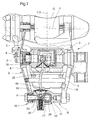
- the brake disc 1 and 2 show a type of disc brake unit trained disc brake, which only partially brake disc 1 not shown below illustrated wheel set of a rail vehicle interacts.
- the brake disc 1 is an axle brake disc, of course, the disc brake can also be used with conventional Interacting wheel brake discs.
- a brake housing 2 in a coupling point 10 to be regarded as held in a fixed position by means of bolts 3 the two cheeks 4 and 5 one double-cheek caliper lever 6 of a brake caliper 7 by one Axis of rotation A rotatably coupled.
- the forceps lever 8 on the other side is in a coupling point 10 'by means of a bolt 9 on Brake housing 2 rotatably coupled, the bolt 9 is around a parallel to the axis of rotation A, visible in Fig.2 in supervision Axis of rotation B rotatably supported on the brake housing 2 and carries eccentrically axially parallel bolt extensions 11, on which the Pliers lever 8 is mounted.
- the longitudinal axes C and D of the Pliers levers 6 and 8 are located in a pliers plane E which runs perpendicular to the plane of the drawing in Fig. 1.
- the axes of rotation A and B are perpendicular to the pliers plane E.
- a pivot arm 12 protrudes from the bolt 9, at the end of which the Piston rod of a brake cylinder as a force output element 13 Braking motor 14 is articulated.
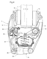
- the two pliers levers 6 and 8 are at one end with the brake disc 1 pressing brake shoes 15 and at their other ends with a they connecting rod 16, one in the embodiment Push rod for axes of rotation parallel to axes of rotation A and B. F, G, H and I rotatable in coupling points 17, 18, 19 and 20 coupled.
- the rod 16 is for coupling with it between the two cheeks 4 and 5 of the pliers levers 6 and 8 extending bearing parts 21 and 22 (Fig.3).
- the rod 16 is integrated with it Wear adjuster 23 equipped, which according to the Wear of the brake shoes 15 the length of the rod 16 enlarged.
- the wear adjuster 23 has, in particular 1 and 3 can be seen, an operating lever 24, the on the pliers lever 6 associated bearing part 21 by a Rotation axis H longitudinal axis 25 of the rod 16 intersecting at right angles is rotatably mounted.
- the rotary lever 24 is by means of itself against the bearing part 21 supporting spring 26 in its Rest position pressed against a stop, not shown held, with at least approximately in the Axis of rotation H extends in the longitudinal direction.
- a rotatable coaxially to the longitudinal axis 25 and axially immovable held on the bearing part 21, towards the bearing part 22 extending threaded spindle 27 is one with a Coil spring equipped one-way rotary coupling 28 or 29 with the Actuating lever 24 and the rotationally fixed about the longitudinal axis 25 held bearing part 21 coupled.
- One with the threaded spindle 27 screwed adjusting nut 31 is on the pliers lever 8 associated bearing part 22 held.
- EP-A-0699846 can instead other types of wear adjusters are used, all that is essential is that it has an actuating lever 24 corresponding lever: For example, it can be similar that known from EP-A-0499971, also already mentioned Wear adjuster, redesigned for extension effect for the pole.
- a control rod 32 Runs between the two cheeks 4 and 5 of the pliers lever 6 a control rod 32, the rounded, rear end in a bearing pan at the free end of the operating lever 24 is applied:
- the control rod 32 is thus via a coupling point 33 coupled to the operating lever 24; in Fig. 2 is the Actuating lever 24 not shown.
- the control rod 32 runs essentially in a Longitudinal axis C contains the plane perpendicular to the pliers plane is approximately parallel to the longitudinal axis C in its central region to avoid collisions with other components, in particular the brake motor 14 to the outside of the brake caliper cranked out.
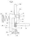
- the front, also rounded end of the Control rod 32 lies in a bearing socket 34 of a rotary lever 35, as is particularly clear from the schematic FIG. 5, but can also be seen from FIG.
- the two-armed Rotary lever 35 is in one in its central region Articulation point 36 is rotatably mounted on an overtravel lever 37.
- the Lift lever 37 is U-shaped so that it is between its two legs 37a and 37b have a recess 38; the bearing pan 34, i.e. the position of the control rod 32 on the rotary lever 35 is located in the region of the recess 38.
- the overtravel lever 37 runs approximately away from the control rod parallel to the rotary lever 35 and projects beyond the control rod side End of the rotary lever 35, he is at this his end with his Leg 37b rotatable on one in Fig.5 only in his here essential sections indicated housing 39 in a Bearing 40 articulated.
- the housing 39 is kept fixed in space, it is preferably mounted on the brake housing 2 or with this one piece.
- the other leg 37a has the Articulation point 36 and forms a stop 41 with its end to a fixed stop part 42, which the housing 39th can belong.
- An opposite to the stop 41 on Lift lever 37 engaging spring 43 loads the lift lever 37 in the closing direction of the stop 41, the spring 43 is against a part 44 preferably belonging to the housing 39 is supported.
- a protective bellows 50 made of elastic material is shown in FIG can be seen which is between the housing 39 and the Control rod 32 at the area emerging from the housing 39 extends and the interior of the housing 39 from contamination protects.
- the free end 35a of the rotary lever 35 is to form a Dead lifting device 44, as can be seen in FIG. 2, on the brake disc side with a distance s a lever part 45 across from; the lever part 45 is an extension of the Swivel arm 12 formed.
- the distance s corresponds to the path starting from the disc brake released with the correct release stroke, the End of the lever part 45 while still applying tension-free force the two brake shoes 15 to the brake disc 1; at the Applying the brake strikes the lever part 45 just against the end 35a of the rotary lever 35.
- this Preload element 49 holds even with relatively large ones Manufacturing deviations, the control rod 32 always in rattle-free and wear-reducing system in the Coupling points 33 and 46 on the actuating lever 24 and the Bearing socket 34.
- the preload of the preload element 49 is smaller than that for actuating the wear adjuster 23 on Actuating lever 24 required force.
- the spring 43 is loaded against the stop 41 with a closing force, which is greater is as the force mentioned at largely from compressive stresses free rod 16. This spring tuning ensures that during hard braking, i.e.
- the actuating lever 24 holds the control rod 32, so that with further rotation of the rotary lever 35 by the further moving lever part 45 via the articulation point 36 of the Stop 41 while rotating the overtravel lever 37 around it Bearing 40 is excavated.
- the stiffness of the Wear adjuster 23 is by the clamping force proportional to the clamping force Resistance to movement and friction between the threaded spindle 27 and the adjusting nut 31 conditionally.
- the two coupling points 33 and 46 of the control rod 32 have Coupling axes 47 and 48, which are at least approximately parallel to the neighboring axes of rotation H and A run; the coupling axis 48 of the coupling point 46 is preferably coaxial with the axis the bearing pan 34.
- the coupling points 33 and 46 can still have further degrees of freedom of rotation for the control rod 32.
- the coupling points 33 and 46 and in particular their coupling axes 47 and 48 at least close to the respective adjacent axes of rotation H or A and at least are almost intersecting the longitudinal axis C.
- the coupling axis 48 of the coupling point 46 coaxial to the axis of rotation A and the coupling axis 47 of the Coupling point 33 with a distance t in the direction of the brake disc 1 runs in front of the axis of rotation H, the distance t being about Half of the average stroke of the control rod 32 when actuated corresponds to the wear adjuster 23.
- the Rod 16 with the wear adjuster 23 extends, based on Fig.2, opposite to the displacement of the brake disc 1 Side offset and slightly rotated in the pliers plane E.
- the Control rod 32 is located in a to the pliers lever 6 unchanged relative position when moving the brake disc sideways 1 it can, regardless of the release or actuation state the disc brake, no actuation stroke on the Exercise operating lever 24 of wear adjuster 23.
- the caliper levers can be articulated on the brake caliper in their central regions on a rod, in this case a pull rod, with an integrated wear adjuster which can be actuated by an actuating lever and act in the shortening direction of the rod, and in their end regions on a brake motor.
- the wear adjuster can be of any type, it only has - as already mentioned - to have an actuating lever.
- the brake caliper can be held on a fixed part, ultimately a vehicle or bogie frame, at a different coupling point than the coupling point 10, the design of a brake caliper unit can possibly be omitted with the brake housing.
- the brake caliper can also be tightened differently, in one of the many known types, for example by means of a brake cylinder coupled directly to the caliper levers or via a lever mechanism.
- List of reference numbers. 1 Brake disc 2nd Brake housing 3rd bolt 4th cheek 5 cheek 6 Forceps lever 7 Brake caliper 8th Forceps lever 9 bolt 10th Coupling point 10 ' Coupling point 11 Stud extension 12th Swivel arm 13 Power output device 14 Brake motor 15 Brake shoe 16 pole 17th Coupling point 18th Coupling point 19th Coupling point 20th Coupling point 21 Bearing part 22 Bearing part 23 Wear adjuster 24th Operating lever 25th Longitudinal axis 26 feather 27 Threaded spindle 28 One-way rotary coupling 29 One-way rotary coupling 30th Housing part 31 Adjusting nut 32 Control rod 33 Coupling point 34 Storage pan 35 Rotary lever 35a The End 36 Articulation point 37 Lift lever 37a leg 37b leg 38 Recess 39 casing 40 Depository 41 attack 42 Stop
Landscapes
- Engineering & Computer Science (AREA)
- Mechanical Engineering (AREA)
- General Engineering & Computer Science (AREA)
- Braking Arrangements (AREA)
Claims (12)
- Frein à disque pour trains de roues, notamment mobiles transversalement, de véhicules sur rails, comportant une pince de frein (7), dont les deux leviers (6;8) sont accouplés, au niveau de premières extrémités, à des mâchoires de frein (15) et, au niveau de leurs autres extrémités ou dans leurs zones médianes, respectivement à un moteur (14) produisant une force de freinage et à une tige (16) qui les relie, frein dans lequel au moins les axes longitudinaux (C;D) des leviers (6;8) de la pince sont situés dans un plan (E) de la pince, perpendiculairement auquel les points d'accouplement (17;18;19;20) présentent des axes de rotation (A;B;F;G;H;I), et la tige (16) possède un dispositif de compensation d'usure (23), qui ajuste la longueur de la tige et peut être actionné à l'aide d'une tringlerie de commande en fonction de la course du moteur (14) produisant la force de freinage, et dans lequel fait partie de la tringlerie de commande une tige de commande (32), qui s'étend essentiellement parallèlement aux leviers (6;8) de la pince et dont les extrémités peuvent être accouplées, de manière à pouvoir tourner autour d'axes d'accouplement (47;48) qui sont au moins approximativement parallèles aux axes de rotation (A;B;F;G;H;I), d'une part, indirectement au moyen d'un levier rotatif (35), à un organe (13) de délivrance de force du moteur (14) produisant la force de freinage et, d'autre part, à un levier d'actionnement (24) du dispositif de compensation d'usure (23),
caractérisé en ce
que les points d'accouplement (33;46) aux extrémités de la tige de commande (32) sont situés, au moins approximativement sur les axes de rotation (A;H) qui font partie des points d'accouplement (10;19) de l'un des leviers (6) de la pince à la tige (16) ou au moteur (14) produisant la force de freinage. - Frein à disque selon la revendication 1, caractérisé on ce qu'au moins l'un des points d'accouplement (33;46) de la tige de commande (32) est situé, lorsqu'on regarde dans sa direction de déplacement pour l'actionnement du dispositif de compensation d'usure (23), à une distance (t), qui correspond approximativement à la moitié de la course de déplacement moyenne de la tige de commande (32) lors de l'actionnement du dispositif de compensation d'usure (23), en avant de l'axe de rotation (H) associé à ce point d'accouplement (33).
- Frein à disque selon la revendication 1 ou 2, caractérisé en ce que les axes d'accouplement (47,48) des points d'accouplement (33;46) de la tige de commande (32) sont situés, pour l'un au moins, approximativement sur et, pour l'autre, à une distance (t) en avant de l'axe de rotation respectif (A;H).
- Frein à disque selon la revendication 2 ou 3, caractérisé en ce que le point d'accouplement (46), situé du côté du moteur produisant la force de freinage, de la tige de commande (32) ou son axe d'accouplement (48) est situé au moins approximativement sur l'axe de rotation respectivement associé (A ou H) et que le point d'accouplement (33), situé du côté du dispositif de compensation d'usure, ou son axe d'accouplement (47) est situé à une distance (t) en avant de l'axe de rotation respectivement associé (A ou H).
- Frein à disque selon la revendication 4, dans lequel la pince de frein (7) possède un point d'accouplement (10) fixe dans l'espace, notamment fixé sur un boítier de frein (2), caractérisé en ce que le point d'accouplement (46), situé du côté du moteur produisant la force de freinage, de lui tige de commande (32) ou son axe d'accouplement (48) est situé au moins approximativement sur l'axe de rotation (A) de ce point d'accouplement (10), fixe dans l'espace, de la pince de frein (7).
- Frein à disque selon une ou plusieurs des revendications précédentes 1 à 5, caractérisé en ce qu'au moins l'un des points d'accouplement (46) de la tige de commande (32) possède un dispositif à course à vide (44) qui absorbe la course de l'organe (13) de délivrance de la force de freinage dans le cas du serrage du frein sans compensation de l'usure.
- Frein à disque selon la revendication 6, caractérisé en ce que le point d'accouplement (46), situé du côté du moteur produisant la force de freinage, de la tige de commande (32) possède un levier rotatif (35), qui fait saillie essentiellement latéralement par rapport à la tige de commande (32) et dont une extrémité comporte un point d'appui pour la tige de commande (32), et dont l'autre extrémité (35a) est située en vis-à-vis d'un élément de levier (45) déplaçable par le moteur (14) produisant la force de freinage, à une distance (s) qui correspond à la course de déplacement de cet élément de levier (45) dans le cas d'an serrage du frein sans compensation de l'usure, et qui est articulé, dans sa section médiane, sur un levier de dépassement de course (37), le levier de dépassement de course (37) possédant, à proximité du point d'articulation (36), une butée (41), chargée par un ressort (43) dans le sens de fermeture, par rapport à un élément (42) maintenu fixe dans l'espace, et étant, à l'autre extrémité, supporté de manière à pouvoir tourner, la charge de la butée (41) par le ressort étant supérieure à la force d'actionnement du dispositif de compensation d'usure (23).
- Frein à disque selon la revendication 7, caractérisé en ce que le levier rotatif (35) et le levier de dépassement de course (37) sont approximativement parallèles entre eux et perpendiculaires à la tige de commande (32), le levier de dépassement de course (37) possédant en son centre un évidement (38), dans lequel est situé le point d'appui de la tige de commande (32) par rapport au levier rotatif (35).
- Frein à disque selon la revendication 7 ou 8, caractérisé en ce que le dispositif à course à vide (44) est disposé dans un boítier fixe (39), qui est fixé notamment sur un boítier de frein (2) et duquel la tige de commande (32) ressort d'une manière étanche grâce à la présence d'un soufflet de protection (50).
- Frein à disque selon la revendication 7, 8 ou 9, caractérise en ce que dans la tige de commande (32), est intégré un élément élastique de précontrainte (49), dont la précontrainte est inférieure à la force nécessaire pour l'actionnement du dispositif de compensation d'usure (23).
- Frein à disque selon une ou plusieurs des revendications précédentes 1 à 10, dans lequel les leviers (6;8) de la pince de frein (7) sont d'une configuration en double joue, caractérisé en ce que la tige de commande (32) s'étend, au moins pour l'essentiel, entre les deux joues (4;5) d'un levier de pince (6).
- Frein à disque selon la revendication 11, caractérisé en ce que la tige de commande (32) s'étend, dans ses parties d'extrémité, au moins approximativement dans un plan qui est perpendiculaire au plan (E) de la pince et qui contient l'axe longitudinal (C) d'un levier (6) de la pince, et comporte, dans sa partie médiane, un décrochement latéral.
Applications Claiming Priority (2)
| Application Number | Priority Date | Filing Date | Title |
|---|---|---|---|
| DE19509540 | 1995-03-16 | ||
| DE19509540A DE19509540C1 (de) | 1995-03-16 | 1995-03-16 | Scheibenbremse für Schienenfahrzeuge |
Publications (3)
| Publication Number | Publication Date |
|---|---|
| EP0732247A2 EP0732247A2 (fr) | 1996-09-18 |
| EP0732247A3 EP0732247A3 (fr) | 1999-03-03 |
| EP0732247B1 true EP0732247B1 (fr) | 2000-11-08 |
Family
ID=7756837
Family Applications (1)
| Application Number | Title | Priority Date | Filing Date |
|---|---|---|---|
| EP95119535A Expired - Lifetime EP0732247B1 (fr) | 1995-03-16 | 1995-12-12 | Frein à disque pour véhicules ferroviaires |
Country Status (3)
| Country | Link |
|---|---|
| EP (1) | EP0732247B1 (fr) |
| DE (2) | DE19509540C1 (fr) |
| ES (1) | ES2152359T3 (fr) |
Cited By (4)
| Publication number | Priority date | Publication date | Assignee | Title |
|---|---|---|---|---|
| DE102011009538A1 (de) | 2010-02-02 | 2011-08-04 | Knorr-Bremse Systeme für Schienenfahrzeuge GmbH, 80809 | Druckstangensteller für Kompakt-Bremszangen-einheiten mit sich direkt am Stellergehäuse abstützenden Verschraubungsteil |
| DE102011009540A1 (de) | 2010-02-02 | 2011-08-04 | Knorr-Bremse Systeme für Nutzfahrzeuge GmbH, 80809 | Druckstangensteller für Kompakt-Bremszangeneinheiten mit gegen einen elastischen Anschlag anschlagbarem Stellhebel |
| EP3683468A1 (fr) | 2019-01-18 | 2020-07-22 | KNORR-BREMSE Systeme für Schienenfahrzeuge GmbH | Dispositif de rattrapage d'usure d'une unité de freinage à pince compacte, et unité de freinage à pince compacte avec un dispositif de rattrapage d'usure |
| EP3683117A1 (fr) | 2019-01-18 | 2020-07-22 | KNORR-BREMSE Systeme für Schienenfahrzeuge GmbH | Dispositif de rattrapage d'usure d'une unité de mâchoire de frein compacte et unité de mâchoire de frein compacte dotée d'un dispositif de rattrapage d'usure |
Families Citing this family (12)
| Publication number | Priority date | Publication date | Assignee | Title |
|---|---|---|---|---|
| DE102007032966B4 (de) * | 2007-07-16 | 2009-11-12 | Knorr-Bremse Systeme für Schienenfahrzeuge GmbH | Lagerungsanordnung für Exzenterwellen |
| CN104879405A (zh) * | 2014-11-18 | 2015-09-02 | 四川制动科技股份有限公司 | 一种闸调器 |
| JP6543149B2 (ja) * | 2015-09-25 | 2019-07-10 | Kyb株式会社 | ブレーキ装置 |
| PL3150458T3 (pl) | 2015-09-29 | 2018-07-31 | Kes Keschwari Electronic Systems Gmbh & Co. Kg | Cylinder hamulcowy ze zintegrowanym nastawnikiem zużycia do pojazdów szynowych |
| DE102015219058B3 (de) | 2015-09-29 | 2017-04-13 | Kes Keschwari Electronic Systems Gmbh & Co. Kg | Bremszylinder mit integriertem Verschleißnachsteller für Schienenfahrzeuge |
| EP3228897B1 (fr) | 2016-04-05 | 2018-04-25 | KES Keschwari Electronic Systems GmbH & Co. KG | Frein comprenant un dispositif de réglage symétrique en fonction de l'usure |
| DE102016205961A1 (de) | 2016-04-05 | 2017-10-05 | Kes Keschwari Electronic Systems Gmbh & Co. Kg | Bremse mit symmetrischem Verschleißnachsteller |
| DE102016226238B4 (de) | 2016-12-27 | 2019-07-04 | Kes Keschwari Electronic Systems Gmbh & Co. Kg | Bremse mit Bremszylinder und integriertem Verschleißnachsteller |
| DE102017106554A1 (de) | 2017-03-27 | 2018-09-27 | Knorr-Bremse Systeme für Schienenfahrzeuge GmbH | Scheibenbremsvorrichtung eines Fahrzeugs mit Bremsbelagverschleißerfassung |
| DE102017106552A1 (de) | 2017-03-27 | 2018-09-27 | Knorr-Bremse Systeme für Schienenfahrzeuge GmbH | Scheibenbremsvorrichtung eines Fahrzeugs mit Temperaturerfassung der Bremsscheibe |
| JP7469140B2 (ja) | 2020-05-26 | 2024-04-16 | ナブテスコ株式会社 | ブレーキ装置 |
| JP7444757B2 (ja) | 2020-10-28 | 2024-03-06 | ナブテスコ株式会社 | ブレーキキャリパ装置 |
Family Cites Families (5)
| Publication number | Priority date | Publication date | Assignee | Title |
|---|---|---|---|---|
| DE3309265A1 (de) * | 1983-03-15 | 1984-09-20 | Knorr-Bremse GmbH, 8000 München | Selbsttaetige, sofortwirkende nachstellvorrichtung fuer den anlegehub von bremsgestaengen von insbesondere schienenfahrzeugen |
| GB2153461B (en) * | 1984-02-01 | 1987-09-03 | Davies & Metcalfe | Disc brake adjustment |
| US4949724A (en) | 1988-12-23 | 1990-08-21 | Mahutte Cornelis K | Method and apparatus for continuous measurement of cardiac output |
| DE4105299A1 (de) * | 1991-02-20 | 1992-08-27 | Knorr Bremse Ag | Zangenartiges bremsgestaenge, insbesondere fuer scheibenbremsen von schienenfahrzeugen |
| DE4431321C2 (de) * | 1994-09-02 | 2000-02-24 | Knorr Bremse Systeme | Bremsgestänge für Fahrzeuge, insbesondere Schienenfahrzeuge |
-
1995
- 1995-03-16 DE DE19509540A patent/DE19509540C1/de not_active Expired - Fee Related
- 1995-12-12 ES ES95119535T patent/ES2152359T3/es not_active Expired - Lifetime
- 1995-12-12 DE DE59508841T patent/DE59508841D1/de not_active Expired - Lifetime
- 1995-12-12 EP EP95119535A patent/EP0732247B1/fr not_active Expired - Lifetime
Cited By (10)
| Publication number | Priority date | Publication date | Assignee | Title |
|---|---|---|---|---|
| DE102011009538A1 (de) | 2010-02-02 | 2011-08-04 | Knorr-Bremse Systeme für Schienenfahrzeuge GmbH, 80809 | Druckstangensteller für Kompakt-Bremszangen-einheiten mit sich direkt am Stellergehäuse abstützenden Verschraubungsteil |
| DE102011009540A1 (de) | 2010-02-02 | 2011-08-04 | Knorr-Bremse Systeme für Nutzfahrzeuge GmbH, 80809 | Druckstangensteller für Kompakt-Bremszangeneinheiten mit gegen einen elastischen Anschlag anschlagbarem Stellhebel |
| WO2011095423A1 (fr) | 2010-02-02 | 2011-08-11 | Knorr-Bremse Systeme für Schienenfahrzeuge GmbH | Actionneur à tige de pression pour des unités d'étrier de frein compactes avec élément fileté prenant appui directement sur le boîtier d'actionneur |
| WO2011095424A2 (fr) | 2010-02-02 | 2011-08-11 | Knorr-Bremse Systeme für Schienenfahrzeuge GmbH | Actionneur à tige de pression pour des unités d'étrier de frein compactes avec levier d'actionnement se déplaçant en butée contre une butée élastique |
| EP3683468A1 (fr) | 2019-01-18 | 2020-07-22 | KNORR-BREMSE Systeme für Schienenfahrzeuge GmbH | Dispositif de rattrapage d'usure d'une unité de freinage à pince compacte, et unité de freinage à pince compacte avec un dispositif de rattrapage d'usure |
| EP3683117A1 (fr) | 2019-01-18 | 2020-07-22 | KNORR-BREMSE Systeme für Schienenfahrzeuge GmbH | Dispositif de rattrapage d'usure d'une unité de mâchoire de frein compacte et unité de mâchoire de frein compacte dotée d'un dispositif de rattrapage d'usure |
| DE102019101342A1 (de) | 2019-01-18 | 2020-07-23 | Knorr-Bremse Systeme für Schienenfahrzeuge GmbH | Verschleißnachsteller einer Kompakt-Bremszangeneinheit, und Kompakt-Bremszangeneinheit mit einem solchen Verschleißnachsteller |
| DE102019101341A1 (de) | 2019-01-18 | 2020-07-23 | Knorr-Bremse Systeme für Schienenfahrzeuge GmbH | Verschleißnachsteller einer Kompakt-Bremszangeneinheit, und Kompakt-Bremszangeneinheit mit einem solchen Verschleißnachsteller |
| DE102019101342B4 (de) | 2019-01-18 | 2020-07-30 | Knorr-Bremse Systeme für Schienenfahrzeuge GmbH | Verschleißnachsteller einer Kompakt-Bremszangeneinheit, und Kompakt-Bremszangeneinheit mit einem solchen Verschleißnachsteller |
| DE102019101341B4 (de) | 2019-01-18 | 2020-07-30 | Knorr-Bremse Systeme für Schienenfahrzeuge GmbH | Verschleißnachsteller einer Kompakt-Bremszangeneinheit, und Kompakt-Bremszangeneinheit mit einem solchen Verschleißnachsteller |
Also Published As
| Publication number | Publication date |
|---|---|
| ES2152359T3 (es) | 2001-02-01 |
| DE59508841D1 (de) | 2000-12-14 |
| EP0732247A2 (fr) | 1996-09-18 |
| EP0732247A3 (fr) | 1999-03-03 |
| DE19509540C1 (de) | 1996-10-02 |
Similar Documents
| Publication | Publication Date | Title |
|---|---|---|
| EP0732247B1 (fr) | Frein à disque pour véhicules ferroviaires | |
| DE1098834B (de) | Scheibenbremse, insbesondere fuer Kraftfahrzeuge | |
| EP3245418A1 (fr) | Frein à disque et élément d'entraînement d'un dispositif de rattrapage d'usure d'un frein à disque | |
| EP0442265B1 (fr) | Accouplement de serrage pour un composant de réglage déplaçable axialement pour le changement de rotation de la griffe sur une rotative typographique | |
| EP0738643B1 (fr) | Unité de pince de frein pour freins à disque pour véhicule, notamment pour véhicules ferroviaires | |
| EP0015582A1 (fr) | Dispositif de freinage pour véhicules ferroviaires | |
| EP0381956B1 (fr) | Dispositif de freinage à sabots pour véhicules ferroviaires | |
| DE2261843B2 (de) | Selbsttaetige, doppeltwirkende bremsgestaengenachstelleinrichtung im bremsgestaenge, insbesondere von schienenfahrzeugen | |
| EP1180080B1 (fr) | Dispositif pour regler et verrouiller de maniere elastique des elements d'aiguillage mobiles | |
| DE4407293C1 (de) | Bremszange für Scheibenbremsen von Schienenfahrzeugen | |
| DE4210828A1 (de) | Bremszange fuer eine elektrohydraulisch betaetigbare zangenscheibenbremse, insbesondere fuer strassenbahnwagen | |
| EP0553450B1 (fr) | Pince pour frein à disque des véhicules ferroviaires | |
| WO2003019021A1 (fr) | Dispositif pour l'actionnement d'un cable | |
| DE102011088848B4 (de) | Bremssystem für Nutzfahrzeuge | |
| DE19605853C1 (de) | Bremsklotzeinheit für Schienenfahrzeuge | |
| DE2449853B2 (de) | Scheibenbremse fuer schienenfahrzeuge | |
| AT274890B (de) | Spurwechseleinrichtung für Schienenfahrzeuge | |
| DE102015106841B4 (de) | Scheibenbremse | |
| EP0666207B1 (fr) | Actionneur électromécanique pour freins à friction | |
| DE3504040A1 (de) | Bremsspielregelung fuer eisenbahnwagen | |
| DE102012107723B4 (de) | Fail-Safe-Vorrichtung, insbesondere Bremseinheit für eine Scheibenbremse | |
| DE2625867C2 (de) | Bremsenanordnung mit mehreren gleichzeitig an Rotorflächen anlegbaren Bremsenteilen | |
| EP0073320A1 (fr) | Dispositif de manoeuvre et de réajustage pour freins à disques à garnitures en segments | |
| DE1455292B2 (de) | Doppeltwirkende selbsttätige Gestängenachstelleinrichtung für das Bremsgestänge eines Eisenbahnwagens | |
| DE2225352A1 (de) | Betaetigungsvorrichtung fuer bremsbacken von scheibenbremsen |
Legal Events
| Date | Code | Title | Description |
|---|---|---|---|
| PUAI | Public reference made under article 153(3) epc to a published international application that has entered the european phase |
Free format text: ORIGINAL CODE: 0009012 |
|
| AK | Designated contracting states |
Kind code of ref document: A2 Designated state(s): DE ES FR GB IT SE |
|
| PUAL | Search report despatched |
Free format text: ORIGINAL CODE: 0009013 |
|
| AK | Designated contracting states |
Kind code of ref document: A3 Designated state(s): DE ES FR GB IT SE |
|
| 17P | Request for examination filed |
Effective date: 19990316 |
|
| GRAG | Despatch of communication of intention to grant |
Free format text: ORIGINAL CODE: EPIDOS AGRA |
|
| 17Q | First examination report despatched |
Effective date: 19990706 |
|
| GRAG | Despatch of communication of intention to grant |
Free format text: ORIGINAL CODE: EPIDOS AGRA |
|
| GRAG | Despatch of communication of intention to grant |
Free format text: ORIGINAL CODE: EPIDOS AGRA |
|
| GRAH | Despatch of communication of intention to grant a patent |
Free format text: ORIGINAL CODE: EPIDOS IGRA |
|
| GRAH | Despatch of communication of intention to grant a patent |
Free format text: ORIGINAL CODE: EPIDOS IGRA |
|
| GRAA | (expected) grant |
Free format text: ORIGINAL CODE: 0009210 |
|
| ITF | It: translation for a ep patent filed |
Owner name: BARZANO' E ZANARDO ROMA S.P.A. |
|
| AK | Designated contracting states |
Kind code of ref document: B1 Designated state(s): DE ES FR GB IT SE |
|
| REF | Corresponds to: |
Ref document number: 59508841 Country of ref document: DE Date of ref document: 20001214 |
|
| ET | Fr: translation filed | ||
| REG | Reference to a national code |
Ref country code: ES Ref legal event code: FG2A Ref document number: 2152359 Country of ref document: ES Kind code of ref document: T3 |
|
| GBT | Gb: translation of ep patent filed (gb section 77(6)(a)/1977) |
Effective date: 20010112 |
|
| PLBE | No opposition filed within time limit |
Free format text: ORIGINAL CODE: 0009261 |
|
| STAA | Information on the status of an ep patent application or granted ep patent |
Free format text: STATUS: NO OPPOSITION FILED WITHIN TIME LIMIT |
|
| 26N | No opposition filed | ||
| REG | Reference to a national code |
Ref country code: GB Ref legal event code: IF02 |
|
| PGFP | Annual fee paid to national office [announced via postgrant information from national office to epo] |
Ref country code: FR Payment date: 20110107 Year of fee payment: 16 |
|
| PGFP | Annual fee paid to national office [announced via postgrant information from national office to epo] |
Ref country code: SE Payment date: 20101221 Year of fee payment: 16 Ref country code: GB Payment date: 20101221 Year of fee payment: 16 |
|
| PGFP | Annual fee paid to national office [announced via postgrant information from national office to epo] |
Ref country code: DE Payment date: 20110218 Year of fee payment: 16 Ref country code: IT Payment date: 20101227 Year of fee payment: 16 |
|
| PGFP | Annual fee paid to national office [announced via postgrant information from national office to epo] |
Ref country code: ES Payment date: 20101222 Year of fee payment: 16 |
|
| REG | Reference to a national code |
Ref country code: SE Ref legal event code: EUG |
|
| GBPC | Gb: european patent ceased through non-payment of renewal fee |
Effective date: 20111212 |
|
| REG | Reference to a national code |
Ref country code: FR Ref legal event code: ST Effective date: 20120831 |
|
| REG | Reference to a national code |
Ref country code: DE Ref legal event code: R119 Ref document number: 59508841 Country of ref document: DE Effective date: 20120703 |
|
| PG25 | Lapsed in a contracting state [announced via postgrant information from national office to epo] |
Ref country code: GB Free format text: LAPSE BECAUSE OF NON-PAYMENT OF DUE FEES Effective date: 20111212 Ref country code: SE Free format text: LAPSE BECAUSE OF NON-PAYMENT OF DUE FEES Effective date: 20111213 Ref country code: DE Free format text: LAPSE BECAUSE OF NON-PAYMENT OF DUE FEES Effective date: 20120703 |
|
| PG25 | Lapsed in a contracting state [announced via postgrant information from national office to epo] |
Ref country code: IT Free format text: LAPSE BECAUSE OF NON-PAYMENT OF DUE FEES Effective date: 20111212 |
|
| PG25 | Lapsed in a contracting state [announced via postgrant information from national office to epo] |
Ref country code: FR Free format text: LAPSE BECAUSE OF NON-PAYMENT OF DUE FEES Effective date: 20120102 |
|
| REG | Reference to a national code |
Ref country code: ES Ref legal event code: FD2A Effective date: 20130703 |
|
| PG25 | Lapsed in a contracting state [announced via postgrant information from national office to epo] |
Ref country code: ES Free format text: LAPSE BECAUSE OF NON-PAYMENT OF DUE FEES Effective date: 20111213 |