EP0731284A1 - Klemmvorrichtung für zylindrische Teile - Google Patents
Klemmvorrichtung für zylindrische Teile Download PDFInfo
- Publication number
- EP0731284A1 EP0731284A1 EP96103638A EP96103638A EP0731284A1 EP 0731284 A1 EP0731284 A1 EP 0731284A1 EP 96103638 A EP96103638 A EP 96103638A EP 96103638 A EP96103638 A EP 96103638A EP 0731284 A1 EP0731284 A1 EP 0731284A1
- Authority
- EP
- European Patent Office
- Prior art keywords
- clamping
- housing
- bush
- segments
- clamping device
- Prior art date
- Legal status (The legal status is an assumption and is not a legal conclusion. Google has not performed a legal analysis and makes no representation as to the accuracy of the status listed.)
- Granted
Links
Images

Classifications
-
- F—MECHANICAL ENGINEERING; LIGHTING; HEATING; WEAPONS; BLASTING
- F16—ENGINEERING ELEMENTS AND UNITS; GENERAL MEASURES FOR PRODUCING AND MAINTAINING EFFECTIVE FUNCTIONING OF MACHINES OR INSTALLATIONS; THERMAL INSULATION IN GENERAL
- F16D—COUPLINGS FOR TRANSMITTING ROTATION; CLUTCHES; BRAKES
- F16D1/00—Couplings for rigidly connecting two coaxial shafts or other movable machine elements
- F16D1/06—Couplings for rigidly connecting two coaxial shafts or other movable machine elements for attachment of a member on a shaft or on a shaft-end
- F16D1/08—Couplings for rigidly connecting two coaxial shafts or other movable machine elements for attachment of a member on a shaft or on a shaft-end with clamping hub; with hub and longitudinal key
- F16D1/09—Couplings for rigidly connecting two coaxial shafts or other movable machine elements for attachment of a member on a shaft or on a shaft-end with clamping hub; with hub and longitudinal key with radial clamping due to axial loading of at least one pair of conical surfaces
- F16D1/093—Couplings for rigidly connecting two coaxial shafts or other movable machine elements for attachment of a member on a shaft or on a shaft-end with clamping hub; with hub and longitudinal key with radial clamping due to axial loading of at least one pair of conical surfaces using one or more elastic segmented conical rings forming at least one of the conical surfaces, the rings being expanded or contracted to effect clamping
- F16D1/095—Couplings for rigidly connecting two coaxial shafts or other movable machine elements for attachment of a member on a shaft or on a shaft-end with clamping hub; with hub and longitudinal key with radial clamping due to axial loading of at least one pair of conical surfaces using one or more elastic segmented conical rings forming at least one of the conical surfaces, the rings being expanded or contracted to effect clamping with clamping effected by ring contraction only
- F16D1/096—Couplings for rigidly connecting two coaxial shafts or other movable machine elements for attachment of a member on a shaft or on a shaft-end with clamping hub; with hub and longitudinal key with radial clamping due to axial loading of at least one pair of conical surfaces using one or more elastic segmented conical rings forming at least one of the conical surfaces, the rings being expanded or contracted to effect clamping with clamping effected by ring contraction only the ring or rings being located between the shaft and the hub
-
- F—MECHANICAL ENGINEERING; LIGHTING; HEATING; WEAPONS; BLASTING
- F16—ENGINEERING ELEMENTS AND UNITS; GENERAL MEASURES FOR PRODUCING AND MAINTAINING EFFECTIVE FUNCTIONING OF MACHINES OR INSTALLATIONS; THERMAL INSULATION IN GENERAL
- F16B—DEVICES FOR FASTENING OR SECURING CONSTRUCTIONAL ELEMENTS OR MACHINE PARTS TOGETHER, e.g. NAILS, BOLTS, CIRCLIPS, CLAMPS, CLIPS OR WEDGES; JOINTS OR JOINTING
- F16B7/00—Connections of rods or tubes, e.g. of non-circular section, mutually, including resilient connections
- F16B7/10—Telescoping systems
- F16B7/14—Telescoping systems locking in intermediate non-discrete positions
- F16B7/149—Telescoping systems locking in intermediate non-discrete positions with a sleeve or ring having a tapered or conical surface
-
- F—MECHANICAL ENGINEERING; LIGHTING; HEATING; WEAPONS; BLASTING
- F16—ENGINEERING ELEMENTS AND UNITS; GENERAL MEASURES FOR PRODUCING AND MAINTAINING EFFECTIVE FUNCTIONING OF MACHINES OR INSTALLATIONS; THERMAL INSULATION IN GENERAL
- F16D—COUPLINGS FOR TRANSMITTING ROTATION; CLUTCHES; BRAKES
- F16D1/00—Couplings for rigidly connecting two coaxial shafts or other movable machine elements
- F16D1/06—Couplings for rigidly connecting two coaxial shafts or other movable machine elements for attachment of a member on a shaft or on a shaft-end
- F16D1/08—Couplings for rigidly connecting two coaxial shafts or other movable machine elements for attachment of a member on a shaft or on a shaft-end with clamping hub; with hub and longitudinal key
- F16D1/09—Couplings for rigidly connecting two coaxial shafts or other movable machine elements for attachment of a member on a shaft or on a shaft-end with clamping hub; with hub and longitudinal key with radial clamping due to axial loading of at least one pair of conical surfaces
- F16D1/093—Couplings for rigidly connecting two coaxial shafts or other movable machine elements for attachment of a member on a shaft or on a shaft-end with clamping hub; with hub and longitudinal key with radial clamping due to axial loading of at least one pair of conical surfaces using one or more elastic segmented conical rings forming at least one of the conical surfaces, the rings being expanded or contracted to effect clamping
- F16D1/094—Couplings for rigidly connecting two coaxial shafts or other movable machine elements for attachment of a member on a shaft or on a shaft-end with clamping hub; with hub and longitudinal key with radial clamping due to axial loading of at least one pair of conical surfaces using one or more elastic segmented conical rings forming at least one of the conical surfaces, the rings being expanded or contracted to effect clamping using one or more pairs of elastic or segmented rings with mutually mating conical surfaces, one of the mating rings being contracted and the other being expanded
Definitions
- the invention relates to a clamping device for cylindrical, axially displaceable or rotating parts (rods or shafts), consisting of coming against the rod or the shaft, distributed over the circumference of the clamping segments with external taper, one enclosing the clamping segments, in the axial Clamping bushing which can be displaced in the direction of the clamping segments with opposite conicity of their contact surface against the conical clamping block which produces a self-locking effect and a pressure-tight housing enclosing the clamping segments and clamping bushing, which is supported on the rod or the shaft by means of seals, the clamping bushing leaving an open space on both sides with a free space acting on the clamping bushing, supported on the housing and imparting the clamping bushing tendency, and a pressure medium access to the spring chamber.
- the clamping situation is ensured by the spring trapping the clamping bush, imparting a tendency to the clamping bushing and / or by pressure medium acting on the clamping bush.
- Fatigue of the spring in the worst case spring break and / or reduction of pressure medium pressure, for example as a result of leakage in the pressure medium system, can lead to an undesired, risky release of the clamping.
- the object of the invention was to develop a clamping device which avoids the risks associated with known clamping devices.
- the object is achieved with a generic clamping device, the clamping bushing of which is supported on both ends by means of ring seals on the housing by means of pressure medium pressure which can be applied on both sides.
- the clamping is caused by the fact that pressure medium is fed into the spring space of the clamping device, under the action of which the clamping bushing expands, which enables the springs catching the clamping bushing to displace the clamping bushing in the direction of attack relative to the clamping segments. If the contact pressure is then released, the clamping bush shrinks, fixing the clamping segments in relation to the rod or shaft.
- pressure medium is in turn fed into the spring chamber, causing a further widening of the clamping bush, furthermore the clamping bush is then also pressurized on the side facing away from the spring chamber, under the action of which the clamping bush is displaced in the opposite direction to the setting direction against the pressure of the adjusting spring , which is accompanied by a loosening of the clamping segments.
- the actual clamping is thus effected via the shrinkage tension inherent in the clamping bush, which is not subject to the risk of impairment.
- the instead of the springs trapping the spring bushing can be supported by making the spring chamber-side pressure application surface of the spring bushing larger than other ends.
- the expansion capacity of the clamping bush can be improved by various measures, such as recesses which are regularly distributed over the surface in one of the corresponding surfaces of the clamping segments and the clamping bush, and which are preferably radial grooves, then also by the fact that between the housing and the clamping bushing, a free space is formed which is delimited in a pressure-tight manner by the seals by means of which the clamping bushing is supported on the housing.
- a modified embodiment of the clamping device dispenses with the clamping bush, the function of which is taken over by a housing enclosing the clamping elements, leaving free space on both sides, with an inner wall which has an opposite conicity to the conicity of the clamping segments, with the solution piston or pistons leading in the housing act on the clamping segments.
- the adjusting effect of the springs acting on the clamping segments can be improved by adjusting pistons which can be acted upon by pressure medium in the housing, for which the same pressure medium is available with which the housing is widened.
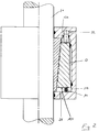
- the clamping device according to FIG. 1 consists of the positionally fixed (111, 111 ') sealed by the rod 21 (112, 112') penetrated housing 11, which is regularly supported over the circumference of the rod 21 and is supported on the rod 21 while leaving a sufficient distance from one another Clamping segments 12 and a clamping bushing 13 surrounding the clamping segments 12, which can be displaced in the axial direction (double arrow A), leaving free spaces 113, 114 on the end faces of the clamping bushing 13, supportingly supported on the lateral surface 131 of the clamping bushing 13 via seals 117, 117 '.
- the corresponding surfaces 121, 132 of the clamping segments 12 and the clamping bush 13 are conical in opposite directions, a conicity being selected which ensures sufficient self-locking between the clamping segments 12 and the clamping bush 13, in the illustrated case approximately 5 °.
- a plurality of ring grooves 133 are formed in the contact surface 132 of the clamping bush 13 .
- a pressure-free space 116 which is shielded by seals 117, 117 ', is formed behind the clamping bush 13.
- the clamping bush 13 In the direction of adjustment of the clamping bush 13 (arrow A '), the clamping bush 13 is caught by a spring 14 imparting a tendency towards the clamping bush 13, the spring chamber 114 can then also be acted upon by pressure medium (31).
- at least two pistons 16 which can be pressurized (32) act on the clamping bushing 13 distributed over the circumference.
- pressure medium is fed in via the feed 31 into the spring chamber 114 when the piston 16 is unloaded, under the action of which the clamping bush 13 enables the bushing to be displaced in the sense of arrow A 'under the action of the spring 14 trapping it relative to the clamping segments 12 experiences.
- the clamping bush 13 shrinks, fixing the clamping segments 12 relative to the rod 21 surrounded by them, using the shrinkage stress.
- pressure medium is in turn fed into the interior of the housing via the feed line 31, which then also results in an expansion of the clamping bush 13, which in the expanded state is now displaced by the pressure-loaded (32) piston 16 in the direction of arrow A ′′ , whereby the clamping of the rod 21 is released via the clamping segments 12.
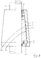
- the clamping device shown in Figure 2 differs from the device shown in Figure 1 only in that the effective spring chamber-side pressure application surface 134 of the clamping bush 113 is designed larger than the opposite pressure application surface 136. This results in the support of the instead of the spring acting on the clamping bush 13 springs 14 by the pressure medium fed into the spring chamber 114 for widening the clamping bush 13.
- the function of the clamping bush provided in the clamping device according to FIG. 1 is also taken over by the housing 41.
- the inner wall 411 of the housing 41 has an opposite conicity to the conicity of the corresponding wall 121 of the clamping segments 12.
- radial grooves 412 are machined into the housing wall 411.
- the mode of operation of the clamping device in FIG. 2 corresponds to that of the clamping device according to FIG. 1.
Landscapes
- Engineering & Computer Science (AREA)
- General Engineering & Computer Science (AREA)
- Mechanical Engineering (AREA)
- Jigs For Machine Tools (AREA)
- Clamps And Clips (AREA)
- Shaping Of Tube Ends By Bending Or Straightening (AREA)
- Discharging, Photosensitive Material Shape In Electrophotography (AREA)
Abstract
Description
- Die Erfindung betrifft eine Klemmvorrichtung für zylindrische, in achsialer Richtung verlagerbare oder drehende Teile (Stangen bzw. Wellen), bestehend aus gegen die Stange bzw. die Welle zur Anlage kommenden, über deren Umfang verteilten Klemmsegmenten mit Außenkonizität, einer die Klemmsegmente einfassenden, in achsialer Richtung gegenüber den Klemmsegmenten verlagerbare Klemmbuchse mit gegenläufiger Konizität ihrer Anlagefläche gegen die Klemmsegmente einer Selbsthemmung bewirkenden Konizität und einem Klemmsegmente und Klemmbuchse einfassenden, sich an der Stange bzw. der Welle über Dichtungen abstützenden druckdichten Gehäuse, die Klemmbuchse unter Belassung beidseitigen Freiraums, mit einer einen Ends auf die Klemmbuchse einwirkenden, sich am Gehäuse abstützenden, der Klemmbuchse Anstelltendenz vermittelten Feder und einem Druckmittelzugang zum Federraum.
- Nach dem Stand der Technik wird die Klemmsituation sichergestellt durch die die Klemmbuchse hinterfangende, der Klemmbuchse Anstelltendenz vermitteltende Feder und/oder durch auf die Klemmbuchse einwirkendes Druckmittel. Ermüdung der Feder, schlimmstenfalls Federbruch und/oder Abbau von Druckmitteldruck, etwa infolge von Leckage im Druckmittelsystem, können hierbei zu ungewollter, risikobehafteter Aufhebung der Klemmung führen.
- Ausgehend vom Stand der Technik lag der Erfindung die Aufgabe zugrunde eine Klemmvorrichtung zu entwickeln, die die mit bekannten Klemmvorrichtungen verbundenen Risiken vermeidet.
- Die Aufgabe wird mit einer gattungsgemäßen Klemmvorrichtung gelöst, deren sich beidends über Ringdichtungen am Gehäuse abstützende Klemmbuchse durch beidends aufbringbaren Druckmitteldruck lösbar ist.
- Die Klemmung wird hierbei dadurch hervorgerufen, daß Druckmittel in den Federraum der Klemmvorrichtung eingespeist wird, unter dessen Einwirkung die Klemmbuchse eine Aufweitung erfährt, die es den die Klemmbuchse hinterfangenden Federn ermöglicht, die Klemmbuchse gegenüber den Klemmsegmenten in Anstellrichtung zu verlagern. Wird der Anstelldruck sodann abgeworfen, schrumpft die Klemmbuchse, die Klemmsegmente gegenüber der Stange bzw. Welle festlegend. Zum Lösen der Klemmvorrichtung wird wiederum Druckmittel in den Federraum eine erneute Aufweitung der Klemmbuchse bewirkend eingespeist, des weiteren wird die Klemnmbuchse dann auch auf der vom Federraum abgekehrten Seite mit Druckmittel beaufschlagt, unter dessen Einwirkung die Klemmbuchse gegen den Druck der Anstellfeder gegenläufig zur Anstellrichtung verlagert wird, womit ein Lösen der Klemmsegmente einhergeht. Die eigentliche Klemmung wird hierbei also über die der Klemmbuchse innewohnende Schrumpfspannung bewirkt, die dem Risiko einer Beeinträchtigung nicht unterliegt.
- Der Anstelleffekt der die Klemmbuchse hinterfangenden Federn kann dadurch eine Unterstützung erfahren, daß die federraumseitige Druckangriffsfläche der Klemmbuchse größer ausgelegt wird als anderen Ends. Das Aufweitungsvermögen der Klemmbuchse läßt sich durch verschiedene Maßnahmen verbessern, so durch in einer der korrespondieren Flächen der Klemmsegmente und der Klemmbuchse regelmäßig über die Fläche verteilte, vom Federraum her zugängliche Rücksprünge, wobei es sich vorzugsweise um Radialnuten handelt, dann auch dadurch, daß zwischen Gehäuse und Klemmbuchse ein Freiraum ausgebildet wird, der durch die Dichtungen, über die sich die Klemmbuchse am Gehäuse abstützt, druckdicht eingegrenzt ist.
- Als vergleichsweise einfache Lösung für das Lösen der Klemmbuchse bietet sich die Beaufschlagung der Klemmbuchse auf der vom Federraum abgekehrten Seite durch sich im Gehäuse führende druckmittelbeaufschlagbare Lösungskolben an, wobei es sich um eine Mehrzahl von über den Umfang der Klemmbuchse verteilte Kolben oder aber um einen Ringkolben handeln kann.
- Eine abgewandelte Ausführungsform der Klemmvorrichtung verzichtet auf die Klemmbuchse, deren Funktion von einem die Klemmelemente, unter Belassung beidseitigen Freiraums, einfassenden Gehäuse mit einer eine gegenläufige Konizität zur Konizität der Klemmsegmente aufweisende Innenwandung mit übernommnen wird, wobei der bzw. die sich im Gehäuse führenden Lösungskolben auf die Klemmsegmente einwirken. Der Anstelleffekt der auf die Klemmsegmente einwirkenden Federn kann durch sich im Gehäuse führende druckmittelbeaufschlagbare Anstellkolben verbessert werden, wofür das gleiche Druckmittel zur Verfügung steht, mit dem die Aufweitung des Gehäuses bewirkt wird.
- In der Zeichnung sind Ausführungsbeispiele beider Versionen der neuen Klemmvorrichtung dargestellt. Es zeigen:
- Figur 1
- die dreiteilige Version der Klemmvorrichtung im Schnitt,
- Figur 2
- eine Ausgestaltung der Klemmvorrichtung nach Figur 1 im Schnitt,
- Figur 3
- die zweiteilige Version der Klemmvorrichtung, ebenfalls im Schnitt.
- Die Klemmvorrichtung nach Figur 1 besteht aus dem lagefixierten (111, 111') von der Stange 21 abgedichtet (112, 112') durchsetzten Gehäuse 11, sich an der Stange 21 abstützende, unter Belassung hinreichenden Abstandes voneinander regelmäßig über den Umfang der Stange 21 verteilte Klemmsegmente 12 und eine die Klemmsegmente 12 umgebende in achsialer Richtung verlagerbare (Doppelpfeil A) Klemmbuchse 13 unter Belassung von Freiräumen 113, 114 an den Stirnseiten der Klemmbuchse 13, sich an der Mantelfläche 131 der Klemmbuchse 13 über Dichtungen 117, 117' abstützend einfaßt. Die korrespondierenden Flächen 121, 132 der Klemmsegmente 12 und der Klemmbuchse 13 sind gegenläufig konisch ausgebildet, wobei eine Konizität gewählt ist, die eine hinreichende Selbsthemmung zwischen den Klemmsegmenten 12 und der Klemmbuchse 13 gewährleistet, im dargestellten Fall ca. 5°. In der Anlagefläche 132 der Klemmbuchse 13 sind beabstandet eine Mehrzahl von Ringnuten 133 ausgebildet. Hinter der Klemmbuchse 13 ist ein durch Dichtungen 117, 117' abgeschirmter druckloser Raum 116 ausgebildet. In Anstellrichtung der Klemmbuchse 13 (Pfeil A') ist die Klemmbuchse 13 von einem der Klemmbuchse 13 Anstelltendenz vermittelten Feder 14 hinterfangen, der Federraum 114 ist dann auch druckmittelbeaufschlagbar (31). Auf der gegenüberliegenden Seite wirken auf die Klemmbuchse 13 über den Umfang verteilt mindestens zwei druckmittelbeaufschlagbare (32) Kolben 16 ein.
- Zum Spannen der Klemmvorrichtung wird über die Einspeisung 31 in den Federraum 114 bei entlastetem Kolben 16 Druckmittel eingespeist, unter dessen Einwirkung die Klemmbuchse 13 eine Verlagerung der Buchse im Sinne des Pfeiles A' unter der Einwirkung der sie hinterfangenden Feder 14 gegenüber den Klemmsegmenten 12 ermöglichende Aufweitung erfährt. Bei anschließender Druckentlastung des Gehäuseinneren schrumpft die Klemmbuchse 13, die Klemmsegmente 12 gegenüber der von ihnen umgebenen Stange 21 unter Ausnutzung der Schrumpfspannung festlegend. Soll die Klemmvorrichtung gelöst werden, wird wiederum Druckmittel über die Zuleitung 31 in das Gehäuseinnere eingespeist womit dann auch wieder eine Aufweitung der Klemmbuchse 13 einhergeht, die in aufgeweitetem Zustand durch den druckmittelbeaufschlagten (32) Kolben 16 nunmehr im Sinne des Pfeiles A'' verlagert wird, womit die Klemmung der Stange 21 über die Klemmsegmente 12 aufgehoben wird.
- Die in Figur 2 dargestellte Klemmvorrichtung unterscheidet sich von der in Figur 1 dargestellten Vorrichtung lediglich dadurch, daß die wirksame federraumseitige Druckangriffsfläche 134 der Klemmbuchse 113 größer ausgelegt ist, als die gegenüberliegende Druckangriffsfläche 136. Daraus resultiert die Unterstützung des Anstelleffekts der auf die Klemmbuchse 13 einwirkenden Federn 14 durch das in den Federraum 114 eingespeiste Druckmittel zur Aufweitung der Klemmbuchse 13.
- Bei der Klemmvorrichtung nach Figur 3 wird die Funktion der bei der Klemmvorrichtung nach Figur 1 vorgesehenen Klemmbuchse vom Gehäuse 41 mitübernommen. Hierbei weist die Innenwandung 411 des Gehäuses 41 eine gegenläufige Konizität zur Konizität der korrespondierenden Wandung 121 der Klemmsegmente 12 auf. Im dargestellten Fall sind in die Gehäusewandung 411 Radialnuten 412 eingearbeitet. Die Funktionsweise der Klemmvorrichtung in Figur 2 entspricht der der Klemmvorrichtung nach Figur 1.
Claims (13)
- Klemmvorrichtung für zylindrische, in achsialer Richtung verlagerbare oder drehende Teile (Stangen bzw. Wellen), bestehend aus gegen die Stange bzw. die Welle (21) zur Anlage kommenden, über deren Umfang verteilten Klemmsegmenten (12) mit Außerkonizität, einer die Klemmsegmente (12) einfassenden, in achsialer Richtung gegenüber den Klemmsegmenten (12) verlagerbaren Klemmbuchse (13) mit gegenläufiger Konizität ihrer Anlagefläche (132) gegen die Klemmsegmente (12) einer Selbsthemmung bewirkender Konizität und einem Klemmsegmente (12) und Klemmbuchse (13) einfassenden, sich an der Stange bzw. der Welle (21) über Dichtungen abstützenden druckdichten Gehäuse (11), die Klemmbuchse (13) unter Belassung beidseitigen Freiraums (113, 114), mit einen Ends auf die Klemmbuchse (13) einwirkenden, sich am Gehäuse (11) abstützenden, der Klemmbuchse (13) Anstelltendenz vermittelnden Federn (14) und einem Druckmittelzugang (31) zum Federraum (114), gekennzeichnet durch eine sich beidends über Ringdichtungen (117, 117
 ) am Gehäuse (11) abstützende, durch beidends aufbringbaren Druckmitteldruck lösbare Klemmbuchse (13).
 - Klemmvorrichtung nach Anspruch 1, dadurch gekennzeichnet, daß die Druckangriffsfläche der Klemmbuchse (13) federraumseitig (114) größer ausgelegt ist als anderen Ends (113).
- Klemmvorrichtung nach Anspruch 1 oder Anspruch 2, dadurch gekennzeichnet, daß in einer der korrespondierenden Flächen der Klemmsegmente (12) und der Klemmbuchse (13) regelmäßig über die Fläche verteilt vom Federraum (114) her zugängliche Rücksprünge (123) ausgebildet sind.
- Klemmvorrichtung nach Anspruch 3, gekennzeichnet durch Rücksprünge in Gestalt von Radialnuten (123).
- Klemmvorrichtung nach einem der Ansprüche 1 bis 4, dadurch gekennzeichnet, daß zwischen Gehäuse (11) und Klemmbuchse (13) ein druckdicht eingegrenzter Freiraum (116) ausgebildet ist.
- Klemmvorrichtung nach einem der Ansprüche 1 bis 5, gekennzeichnet durch eine Konizität ≦ 5°
- Klemmvorrichtung nach einem der Ansprüche 1 bis 6, gekennzeichnet durch eine Mehrzahl von sich im Gehäuse (11) führenden, regelmäßig über den Umfang der Klemmbuchse (13) verteilten, druckmittelbeaufschlagbaren Lösungskolben (16).
- Klemmvorrichtung nach einem der Ansprüche 1 bis 6, gekennzeichnet durch einen sich im Gehäuse (11) führenden, auf die Klemmbuchse (13) einwirkenden, druckmittelbeaufschlagbaren ringförmigen Lösungskolben.
- Abwandlung der Klemmvorrichtung, dadurch gekennzeichnet, daß die Funktion der Klemmbuchse von einem die Klemmelemente (12) unter Belassung beidseitigen Freiraums einfassenden Gehäuse (41) mit einer eine gegenläufige Konizität zur Konizität der durch Federkraft (14) anstellbaren Klemmelemente (12) aufweisenden Innenwandung (411) mitübernommen wird, wobei der bzw. die sich im Gehäuse (41) führende Lösungskolben (16) auf die Klemmsegmente (12) einwirken.
- Klemmvorrichtung nach Anspruch 9, dadurch gekennzeichnet, daß die Anstellfedern (14) sich über eine Ringscheibe an den Klemmsegmenten (12) abstützen.
- Klemmvorrichtung nach Anspruch 9 oder Anspruch 10, gekennzeichnet durch sich im Gehäuse (41) führende, die Wirkung der Anstellfedern (14) unterstützende, gegen die Klemmelemente (12) zur Anlage kommende druckmittelbeaufschlagbare Kolben.
- Klemmvorrichtung nach einem der Ansprüche 1 bis 11, gekennzeichnet durch ein lagefixiertes Gehäuse (11 bzw. 41).
- Klemmvorrichtung nach einem der Ansprüche 1 bis 11, gekennzeichnet durch ein mit der Welle (21) drehendes Gehäuse (11 bzw. 41) mit Druckmittelzuführungen über Drehverbindungen.
Applications Claiming Priority (2)
| Application Number | Priority Date | Filing Date | Title |
|---|---|---|---|
| DE19508175A DE19508175A1 (de) | 1995-03-09 | 1995-03-09 | Klemmvorrichtung für zylindrische, in achsialer Richtung verlagerbare oder drehende Teile |
| DE19508175 | 1995-03-09 |
Publications (2)
| Publication Number | Publication Date |
|---|---|
| EP0731284A1 true EP0731284A1 (de) | 1996-09-11 |
| EP0731284B1 EP0731284B1 (de) | 2001-06-13 |
Family
ID=7756005
Family Applications (1)
| Application Number | Title | Priority Date | Filing Date |
|---|---|---|---|
| EP96103638A Expired - Lifetime EP0731284B1 (de) | 1995-03-09 | 1996-03-08 | Klemmvorrichtung für zylindrische Teile |
Country Status (3)
| Country | Link |
|---|---|
| EP (1) | EP0731284B1 (de) |
| AT (1) | ATE202189T1 (de) |
| DE (2) | DE19508175A1 (de) |
Cited By (4)
| Publication number | Priority date | Publication date | Assignee | Title |
|---|---|---|---|---|
| EP1528267A1 (de) * | 2003-10-27 | 2005-05-04 | SITEMA GmbH & Co. KG | Feststellvorrichtung |
| EP1813823A2 (de) | 2006-01-31 | 2007-08-01 | SITEMA GmbH & Co. KG | Klemmvorrichtung |
| DE102010021859A1 (de) * | 2010-05-28 | 2011-12-01 | Schunk Gmbh & Co. Kg Spann- Und Greiftechnik | Brems- und/oder Feststellvorrichtung eines auf einer Schiene verfahrbaren Schlittens |
| CN104912937A (zh) * | 2015-06-20 | 2015-09-16 | 苏州蓝王机床工具科技有限公司 | 易于拆卸的轴套结构 |
Families Citing this family (4)
| Publication number | Priority date | Publication date | Assignee | Title |
|---|---|---|---|---|
| DE19728457B4 (de) * | 1997-07-03 | 2004-01-15 | Ringfeder Vbg Gmbh | Hydraulisch spannbares Element zum kraftschlüssigen Verbinden eines zylindrischen Bauteils mit einem dazu konzentrisch angeordneten Körper |
| DE19736132A1 (de) * | 1997-08-20 | 1999-03-04 | Daimler Benz Ag | Klemmvorrichtung für ein axial bewegliches Bauteil |
| DE102010027152B4 (de) * | 2010-07-14 | 2019-03-28 | Jean-Claude Montandon | Spannvorrichtung zum Spannen eines Werkstücks |
| CN102954323B (zh) * | 2012-11-12 | 2015-06-03 | 华南理工大学 | 一种用于柔顺机构微动平台的可控楔块预紧机构 |
Citations (2)
| Publication number | Priority date | Publication date | Assignee | Title |
|---|---|---|---|---|
| DE1804857A1 (de) * | 1968-10-24 | 1970-05-21 | Siegfried Haenchen | Klemmhuelse fuer eine axial verschiebbare Kolbenstange |
| US5492430A (en) * | 1994-10-14 | 1996-02-20 | Carl A. Hammoms | Telescopic tubes locking device |
Family Cites Families (2)
| Publication number | Priority date | Publication date | Assignee | Title |
|---|---|---|---|---|
| CH567191A5 (en) * | 1973-07-03 | 1975-09-30 | Humes Ltd | Securing hub to shaft by friction - created by hydraulically driving conical sleeve between hub and shaft |
| DE4126897A1 (de) * | 1991-08-14 | 1993-02-18 | Rexroth Mannesmann Gmbh | Hydraulisches klemmsystem |
-
1995
- 1995-03-09 DE DE19508175A patent/DE19508175A1/de not_active Withdrawn
-
1996
- 1996-03-08 EP EP96103638A patent/EP0731284B1/de not_active Expired - Lifetime
- 1996-03-08 AT AT96103638T patent/ATE202189T1/de not_active IP Right Cessation
- 1996-03-08 DE DE59607059T patent/DE59607059D1/de not_active Expired - Fee Related
Patent Citations (2)
| Publication number | Priority date | Publication date | Assignee | Title |
|---|---|---|---|---|
| DE1804857A1 (de) * | 1968-10-24 | 1970-05-21 | Siegfried Haenchen | Klemmhuelse fuer eine axial verschiebbare Kolbenstange |
| US5492430A (en) * | 1994-10-14 | 1996-02-20 | Carl A. Hammoms | Telescopic tubes locking device |
Cited By (6)
| Publication number | Priority date | Publication date | Assignee | Title |
|---|---|---|---|---|
| EP1528267A1 (de) * | 2003-10-27 | 2005-05-04 | SITEMA GmbH & Co. KG | Feststellvorrichtung |
| US7178639B2 (en) | 2003-10-27 | 2007-02-20 | Sitema Gmbh & Co. Kg | Locking device |
| EP1813823A2 (de) | 2006-01-31 | 2007-08-01 | SITEMA GmbH & Co. KG | Klemmvorrichtung |
| DE102010021859A1 (de) * | 2010-05-28 | 2011-12-01 | Schunk Gmbh & Co. Kg Spann- Und Greiftechnik | Brems- und/oder Feststellvorrichtung eines auf einer Schiene verfahrbaren Schlittens |
| DE102010021859B4 (de) * | 2010-05-28 | 2012-05-03 | Schunk Gmbh & Co. Kg Spann- Und Greiftechnik | Brems- und/oder Feststellvorrichtung eines auf einer Schiene verfahrbaren Schlittens |
| CN104912937A (zh) * | 2015-06-20 | 2015-09-16 | 苏州蓝王机床工具科技有限公司 | 易于拆卸的轴套结构 |
Also Published As
| Publication number | Publication date |
|---|---|
| DE19508175A1 (de) | 1996-09-12 |
| ATE202189T1 (de) | 2001-06-15 |
| EP0731284B1 (de) | 2001-06-13 |
| DE59607059D1 (de) | 2001-07-19 |
Similar Documents
| Publication | Publication Date | Title |
|---|---|---|
| DE69927903T2 (de) | Wellendichtungsvorrichtung mit einer stopfbüchsenpackung | |
| DE3505721C2 (de) | Feuerring-Anordnung für eine Brennkraftmaschine | |
| DE4300191A1 (de) | Dichtung aus Metall | |
| DE3739179C1 (de) | Dichtungsanordnung | |
| EP3249374A1 (de) | Druckprüfvorrichtung | |
| EP0731284A1 (de) | Klemmvorrichtung für zylindrische Teile | |
| EP1321693B1 (de) | Doppelrollbalg-Federungseinrichtung | |
| EP0590188A1 (de) | Presswerkzeug | |
| EP0640764B1 (de) | Kolbenkompressor | |
| DE2930578C3 (de) | Buchse aus elastischem Material für eine Verbindung | |
| DE69803800T2 (de) | Leicht austauschbarer isolator und montagemethode dafür | |
| EP0124471A1 (de) | Werkzeug zur Prüfung von Rohren in einer Rohrprüfpresse | |
| DE2900784B2 (de) | Stopfen zum Verschließen schadhafter Rohre eines Wärmetauschers | |
| DE3901474A1 (de) | Vorrichtung zur befestigung der einlage von hohlladungen oder projektilbildenden ladungen | |
| EP0302272A1 (de) | Wärmespeicher, insbesondere Latentwärmespeicher | |
| DE2953386C2 (de) | Vorrichtung zur Erzeugung von Höchstdruck | |
| EP0097619B1 (de) | Kolbenmaschine mit wenigstens zwei Kolben | |
| EP0234283A1 (de) | Druckaufbaudorn zum druckdichten Befestigen eines Rohres in einer Öffnung eines Rohrbodens | |
| DE2816931C3 (de) | Vorrichtung an einem Druckzyklon | |
| DE2644576A1 (de) | Hydraulische spannvorrichtung | |
| DE2738527A1 (de) | Vorrichtung zum spannen von kreiszylinderischen werkzeugteilen | |
| EP0340338B1 (de) | Rohrverbindung | |
| DE1750740C3 (de) | Hydraulikspeicher für den Antrieb elektrischer Schaltgeräte | |
| DE4438931C2 (de) | Hydrolager | |
| DE102021112742A1 (de) | Dichtungseinrichtung für eine Stange |
Legal Events
| Date | Code | Title | Description |
|---|---|---|---|
| PUAI | Public reference made under article 153(3) epc to a published international application that has entered the european phase |
Free format text: ORIGINAL CODE: 0009012 |
|
| AK | Designated contracting states |
Kind code of ref document: A1 Designated state(s): AT CH DE FR GB IT LI |
|
| 17P | Request for examination filed |
Effective date: 19970304 |
|
| 17Q | First examination report despatched |
Effective date: 19981222 |
|
| GRAG | Despatch of communication of intention to grant |
Free format text: ORIGINAL CODE: EPIDOS AGRA |
|
| GRAG | Despatch of communication of intention to grant |
Free format text: ORIGINAL CODE: EPIDOS AGRA |
|
| GRAH | Despatch of communication of intention to grant a patent |
Free format text: ORIGINAL CODE: EPIDOS IGRA |
|
| GRAH | Despatch of communication of intention to grant a patent |
Free format text: ORIGINAL CODE: EPIDOS IGRA |
|
| GRAA | (expected) grant |
Free format text: ORIGINAL CODE: 0009210 |
|
| AK | Designated contracting states |
Kind code of ref document: B1 Designated state(s): AT CH DE FR GB IT LI |
|
| PG25 | Lapsed in a contracting state [announced via postgrant information from national office to epo] |
Ref country code: IT Free format text: LAPSE BECAUSE OF FAILURE TO SUBMIT A TRANSLATION OF THE DESCRIPTION OR TO PAY THE FEE WITHIN THE PRESCRIBED TIME-LIMIT;WARNING: LAPSES OF ITALIAN PATENTS WITH EFFECTIVE DATE BEFORE 2007 MAY HAVE OCCURRED AT ANY TIME BEFORE 2007. THE CORRECT EFFECTIVE DATE MAY BE DIFFERENT FROM THE ONE RECORDED. Effective date: 20010613 Ref country code: GB Free format text: LAPSE BECAUSE OF FAILURE TO SUBMIT A TRANSLATION OF THE DESCRIPTION OR TO PAY THE FEE WITHIN THE PRESCRIBED TIME-LIMIT Effective date: 20010613 Ref country code: FR Free format text: LAPSE BECAUSE OF FAILURE TO SUBMIT A TRANSLATION OF THE DESCRIPTION OR TO PAY THE FEE WITHIN THE PRESCRIBED TIME-LIMIT Effective date: 20010613 |
|
| REF | Corresponds to: |
Ref document number: 202189 Country of ref document: AT Date of ref document: 20010615 Kind code of ref document: T |
|
| REF | Corresponds to: |
Ref document number: 59607059 Country of ref document: DE Date of ref document: 20010719 |
|
| GBV | Gb: ep patent (uk) treated as always having been void in accordance with gb section 77(7)/1977 [no translation filed] |
Effective date: 20010613 |
|
| EN | Fr: translation not filed | ||
| PG25 | Lapsed in a contracting state [announced via postgrant information from national office to epo] |
Ref country code: AT Free format text: LAPSE BECAUSE OF NON-PAYMENT OF DUE FEES Effective date: 20020308 |
|
| PG25 | Lapsed in a contracting state [announced via postgrant information from national office to epo] |
Ref country code: LI Free format text: LAPSE BECAUSE OF NON-PAYMENT OF DUE FEES Effective date: 20020331 Ref country code: CH Free format text: LAPSE BECAUSE OF NON-PAYMENT OF DUE FEES Effective date: 20020331 |
|
| PLBE | No opposition filed within time limit |
Free format text: ORIGINAL CODE: 0009261 |
|
| STAA | Information on the status of an ep patent application or granted ep patent |
Free format text: STATUS: NO OPPOSITION FILED WITHIN TIME LIMIT |
|
| 26N | No opposition filed | ||
| REG | Reference to a national code |
Ref country code: CH Ref legal event code: PL |
|
| PGFP | Annual fee paid to national office [announced via postgrant information from national office to epo] |
Ref country code: DE Payment date: 20030527 Year of fee payment: 8 |
|
| PG25 | Lapsed in a contracting state [announced via postgrant information from national office to epo] |
Ref country code: DE Free format text: LAPSE BECAUSE OF NON-PAYMENT OF DUE FEES Effective date: 20041001 |