EP0731204B1 - Sèche-linge à condensation avec dispositif pour receuillir l'eau de condensation dans un conteneur - Google Patents
Sèche-linge à condensation avec dispositif pour receuillir l'eau de condensation dans un conteneur Download PDFInfo
- Publication number
- EP0731204B1 EP0731204B1 EP95202465A EP95202465A EP0731204B1 EP 0731204 B1 EP0731204 B1 EP 0731204B1 EP 95202465 A EP95202465 A EP 95202465A EP 95202465 A EP95202465 A EP 95202465A EP 0731204 B1 EP0731204 B1 EP 0731204B1
- Authority
- EP
- European Patent Office
- Prior art keywords
- tank
- cover
- dryer
- collecting
- laundry dryer
- Prior art date
- Legal status (The legal status is an assumption and is not a legal conclusion. Google has not performed a legal analysis and makes no representation as to the accuracy of the status listed.)
- Expired - Lifetime
Links
- 238000009833 condensation Methods 0.000 title claims description 33
- 230000005494 condensation Effects 0.000 title claims description 33
- XLYOFNOQVPJJNP-UHFFFAOYSA-N water Substances O XLYOFNOQVPJJNP-UHFFFAOYSA-N 0.000 title description 13
- 239000007788 liquid Substances 0.000 claims description 26
- 238000001035 drying Methods 0.000 claims description 13
- 238000007789 sealing Methods 0.000 claims description 5
- 241001274961 Rubus repens Species 0.000 description 5
- 230000005484 gravity Effects 0.000 description 5
- 238000012546 transfer Methods 0.000 description 4
- 238000010276 construction Methods 0.000 description 3
- 238000001816 cooling Methods 0.000 description 3
- 239000002184 metal Substances 0.000 description 3
- 230000002547 anomalous effect Effects 0.000 description 2
- 230000008901 benefit Effects 0.000 description 2
- 230000015572 biosynthetic process Effects 0.000 description 2
- 238000010586 diagram Methods 0.000 description 2
- 238000010981 drying operation Methods 0.000 description 2
- 230000000694 effects Effects 0.000 description 2
- 238000009413 insulation Methods 0.000 description 2
- 239000002991 molded plastic Substances 0.000 description 2
- 230000002093 peripheral effect Effects 0.000 description 2
- 230000009471 action Effects 0.000 description 1
- 230000004931 aggregating effect Effects 0.000 description 1
- 230000003466 anti-cipated effect Effects 0.000 description 1
- 238000013459 approach Methods 0.000 description 1
- 230000002301 combined effect Effects 0.000 description 1
- 238000004891 communication Methods 0.000 description 1
- 230000006835 compression Effects 0.000 description 1
- 238000007906 compression Methods 0.000 description 1
- 230000008878 coupling Effects 0.000 description 1
- 238000010168 coupling process Methods 0.000 description 1
- 238000005859 coupling reaction Methods 0.000 description 1
- 239000012530 fluid Substances 0.000 description 1
- 238000003780 insertion Methods 0.000 description 1
- 230000037431 insertion Effects 0.000 description 1
- 238000009434 installation Methods 0.000 description 1
- 238000000034 method Methods 0.000 description 1
- 238000012544 monitoring process Methods 0.000 description 1
- 238000000465 moulding Methods 0.000 description 1
- 239000004033 plastic Substances 0.000 description 1
- 229920003023 plastic Polymers 0.000 description 1
- 230000008569 process Effects 0.000 description 1
- 230000001681 protective effect Effects 0.000 description 1
- 238000005086 pumping Methods 0.000 description 1
- 238000009423 ventilation Methods 0.000 description 1
- 230000000007 visual effect Effects 0.000 description 1
- 239000002699 waste material Substances 0.000 description 1
Images


Classifications
-
- D—TEXTILES; PAPER
- D06—TREATMENT OF TEXTILES OR THE LIKE; LAUNDERING; FLEXIBLE MATERIALS NOT OTHERWISE PROVIDED FOR
- D06F—LAUNDERING, DRYING, IRONING, PRESSING OR FOLDING TEXTILE ARTICLES
- D06F39/00—Details of washing machines not specific to a single type of machines covered by groups D06F9/00 - D06F27/00
- D06F39/12—Casings; Tubs
- D06F39/14—Doors or covers; Securing means therefor
-
- D—TEXTILES; PAPER
- D06—TREATMENT OF TEXTILES OR THE LIKE; LAUNDERING; FLEXIBLE MATERIALS NOT OTHERWISE PROVIDED FOR
- D06F—LAUNDERING, DRYING, IRONING, PRESSING OR FOLDING TEXTILE ARTICLES
- D06F58/00—Domestic laundry dryers
- D06F58/20—General details of domestic laundry dryers
- D06F58/24—Condensing arrangements
-
- D—TEXTILES; PAPER
- D06—TREATMENT OF TEXTILES OR THE LIKE; LAUNDERING; FLEXIBLE MATERIALS NOT OTHERWISE PROVIDED FOR
- D06F—LAUNDERING, DRYING, IRONING, PRESSING OR FOLDING TEXTILE ARTICLES
- D06F37/00—Details specific to washing machines covered by groups D06F21/00 - D06F25/00
- D06F37/42—Safety arrangements, e.g. for stopping rotation of the receptacle upon opening of the casing door
Definitions
- This invention relates to a laundry dryer for household use, being of the top-loading type with arrangements for collecting condensation water in a container.
- condensation laundry dryers which do not require to be installed close to a water system connection, and which usually have some rinse, cooling or condensation water draining arrangements associated therewith, since steam (not to be released to the environment) is caused to condensate from the drying process therein by a stream of cooling air.
- Such machines include of necessity a condensate collecting tank whose capacity is at least equal to the volume of condensate produced by one drying cycle when in maximum load conditions and which requires to be emptied periodically, so that it must be provided detachable.
- the tank is taken out through a front door in the machine by a horizontal sliding movement.
- a further disadvantage comes from the liquid being possibly spilled out of the condensation water collecting tank housing compartment, open to the front.
- Front loading laundry dryers have also been provided with the tank placed in the upper area of the machine, inside an open front compartment whence the tank can be slid out. This does make for easier tank handling and water level checking, but is at clash with the consumer's aesthetic demands and cannot provide full protection against overflow and spillage, just as when the tank is installed in the lower area.
- top loading machines i.e. machines having no front doors
- machines having no front doors have been proposed which have the tank placed between the machine top cover and the rotating laundry-drying basket (see EP-A-0 484 225).
- the tank be provided with automatic closure tight fittings for connection to a condensate delivery line.
- the flat cover must be a significant thickness and formed of an outer cover and inner cover separated by a suitable gap in the 2 to 3 cm range.
- This volume may amount to a few liters, and represents an unnecessary waste.
- the present invention obviates all these drawbacks and provides a top loading laundry dryer with collecting tank for the condensation water, wherein the cover top is provided with a housing for a collecting tank to be placed removably into the housing with a flat top surface coplanar with the cover top surface.
- the housing is provided with two openings in its lower portion to enable the tank to be joined to an intake valving system and an overflow collecting means.
- the valving system is conveniently constructed to cut off any flow of condensate to the tank if the latter is not there or does not fit properly in its housing.
- the valving system is mounted in a gutter for catching any overflowing liquid or condensation dewdrops and recirculate them to the condensation circuit, thereby providing double protection against any liquid spill to the machine interior.
- the gutter is conveniently formed in the handhole bezel with which top loading dryers come inherently equipped.
- the collecting tank is provided with an internal intake conduit which is open at the top and communicated to the outside at the bottom for its connection to the valving system, and with an internal overflow conduit which also is open at the top and communicated to the outside at the bottom to discharge any overflow into the gutter.
- the two intake and overflow conduits are disposed near a front wall of the tank, which wall forms a handgrip for pulling the tank out of its housing which is offset from the tank center of gravity under any fill conditions.
- the tank housing in the cover is closed at the bottom by an inner cover wall having a monotonic downward slope from a rear portion of the machine toward the front thereof and to the overflow and condensate collecting gutter.
- the drum loading door is provided with a resilient sealing gasket.
- the tank is provided with a float type of level indicator.
- FIG. 1 shown therein is an exploded overall perspective view of a laundry dryer embodying the present invention.
- the dryer is compact in size and comprises a box-type body 1, generally of enamelled sheet metal, in the form of a right parallelepipedon having a depth P, illustratively of 60 cm, height H of 85 cm, and width L of 40 cm.
- Depth and width refer to the normal conditions of installation and use anticipated.
- the box-type body 1 is closed at the top by a cover 2, which can be swung open about a hinge 3 located near the rear corner edge of the body, on which a known control and program panel 74 locates.
- the box-type body conventionally accommodates a cylindrical drum (not shown in the FIgure) rotating about a horizontal axis and being provided on its periphery with an unlockable door made accessible by opening the cover 2, through which laundry is introduced into the rotating drum or basket for drying.
- the drum illustratively has a diameter such that most of the box-type body inside volume is occupied by the drum which, for easy introduction of the laundry, should be placed with its peripheral top as close as possible to the cover.
- a rectangular hoousing 4 is formed in the cover thickness which is closed downwardly by an inner cover 27 which extends into the box-type body down to a suitable depth limited by the space requirements of the rotating drum.
- a collecting tank 5 for the condensation liquid is accommodated removably in the housing 4.
- the housing 4 and tank 5 are suitably shaped to make best use of the available interior volume of the machine.
- the tank 5 is suitably provided, near the front wall 6 of the machine body, with a handgrip 51 for removing it and a lens 52 or clear window to view its fill level therethrough.
- a ventilation grid which allows cooling air for an internal condenser to be drawn in (or even blown out).
- suction or ejection could take place through the machine bottom, if the latter is raised off the floor on rest feet, but with the inflow and outflow substantially separated from each other.
- a heat exchanger/steam condenser Provided in the lower portion of the box-type body, not shown in Figure 1, are a heat exchanger/steam condenser, a condensation fluid collecting pan, and motive members for driving rotatively the drum, suction fans and a condensation liquid transfer pump.
- FIG. 1 shows in block diagram form the construction of the laundry dryer of Figure 1.
- a stream of heated air is flowed in a closed loop through the drum 31, it being admitted through a side wall 7 or tympan end of the drum and discharged through the opposite wall 8.
- the heated air vaporizes the liquid with which the laundry is soaked.
- the stream is induced by a fan 9 which directs the moisture-laden warm air into a heat exchanger/condenser 10.
- the exchanger is crossed, in counterflow or crossflow relationship, by a stream of cool air, drawn in from the environment, induced by a fan 11, so that the moist warm air is cooled and moisture condensed in the exchanger.
- the moisture-free cool air is introduced, in closed loop circulation, back into the drum 31 after being heated by electric resistance heaters 12, while the heated condensation air is exhausted to the environment.
- the condensation liquid which forms in the heat exchanger is discharged to a collecting pan 13, which may be integral with the condenser, and by means of a pump 14 is directed into the collecting tank 5 for the liquid through a safety valve device 53 to be explained.
- the operation of the laundry dryer is controlled by a programmer 15 which operates the various electric and mechanical members and detects the liquid level in the pan 13 by means of a pressure switch 16 or an equivalent sensor, to cease operation on the occurrence of anomalous conditions, such as the pan 13 becoming overfilled.
- the inner cover 27 which closes the bottom of the housing 4 for the condensation liquid collecting tank 5 is suitably connected to an overflow and condensation dewdrop collecting pan 17 which discharges any overflow and condensate to the pan 13, preferably under a head where the pan 13 is in communication with the air of the drying circuit, through a drain conduit 18.
- Figure 3 is a front-to-rear sectional view of the upper portion of the laundry dryer to bring out some of its constructional details.
- the box-type body 1 is provided at the top with a handhole bezel 19, preferably a plastics moulding, having at its center a rectangular access slip to provide access to the drying drum, with walls which lead funnel-like on four sides to a location close to the outer surface of the drum 31.
- a handhole bezel 19 preferably a plastics moulding, having at its center a rectangular access slip to provide access to the drying drum, with walls which lead funnel-like on four sides to a location close to the outer surface of the drum 31.
- the handhole bezel is sunk into the box-type body to form a gutter 20 for collecting overflow from the tank 5.
- the gutter is provided with a drain port 23 which is connected to the condensation liquid collecting pan by a pipe 24.
- Hinged to the handhole bezel on the rearward side thereof, is a cover which closes the box-type body top and the access slip formed by the handhole bezel 19.
- the cover also is a box-type construction formed of a flat top frame or cover 26 of enamelled sheet metal, bounding a rectangular opening, and a bottom wall or inner cover 27 of moulded plastics.
- the inner cover is not flat but has a central zone which is sunk into the handhole bezel slip 19 and merges with the walls of the latter to form a housing 4, which is rectangular in plan view and open upwardly, for the tank 5 which is inserted thereinto through the cover opening.
- the bottom wall of the central zone of the inner cover is inclined with a monotonic downward slope from the rear portion to the front portion.
- the front edge of the cover is completed by a molded plastics grille 21 which is expediently formed with a handle for opening the cover.
- the drying drum 31 is conventionally provided with a door 41 hinged about a generatrix line 32 of the drum.
- the door 41 is conventionally provided with an opening handle 33 which also functions as a lock when in the closed position.
- the door 41 is provided with a resilient lip seal 34 to ensure a substantially tight fit between the door 41 and the drum 31.
- snap-action holding devices may be suitably arranged to act between tank and the cover without affecting the ease of removal thereof.
- the tank 5 withdrawal is particularly ergonomic because the tank can be grasped near the front at standard working surface level.
- the inner cover provides a bearing surface for the rear edge of the tank, which can be raised partially and effortlessly with its front portion and slid on the inner cover with its rear portion such that the tank volume will move toward the front and the operator. In this position, the whole tank can be raised without reach and is extremely facilitated.
- the sides of the drum mounted for rotation about a center shaft, are perforated near the shaft to admit heated air into the drum and exhaust moisture-laden air from the drum.
- the drying air delivery and return channels are connected to the drum by means of seals, preferably labyrinth seals, whose fit is less than perfect, so that a minimal volume of relatively moist warm air is let out past the seals.
- This motion has the pattern shown by arrows 36, when the drum 3 is turning with its top in the direction of arrow 35.
- this problem is substantially obviated by the inner cover interposed between the tank and the stream of moist air forming an effective thermal insulation shield which allows the inner cover to become heated by the heat transferred by the convective motion of the air inside the slip, with but minimal leakage to the tank.
- the direct contact of the bottom wall of the inner cover with the tank can be minimized by providing elongate ribs in a front-to-rear direction, for example, either across the wall of the inner cover or the juxtaposed one of the tank, so that an air space is left therebetween which has a thickness on the order of few millimeters and excellent exterior sound as well as thermal insulation can be provided.
- ribs 75 formed on the inner cover, at the bottom of the housing 4. This largely obviates the formation of condensation water on the wall under the inner cover.
- Figure 4 shows an exploded perpspective view of an embodiment which achieves the same spacing and interspace formation effect between the inner cover and the tank bottom while enabling the tank 5 capacity to be maximized.
- the tank 5 is provided with two expansion wings 51, 52 which extend along the tank sides flush with its top wall.
- the wings are received within the cover thickness and bear on two side guides 53, 54 set in the inner cover.
- the bottom wall 55 of the tank can be held off the bottom 56 of the housing formed by the inner cover, and the tank capacity be concurrently increased by the volumes of the wings which act as floodplains for tank overfill conditions.
- Figure 5 is a sectional view in the machine front-to-rear direction of a preferred embodiment of the intake valving system 53 for filling the collecting tank, and shows in greater detail the relative arrangement of the tank, the inner cover, and the handhole bezel.
- a cylindrical sleeve 22 Formed in the handhole bezel 19, inwards of the collecting gutter 20, is a cylindrical sleeve 22 having an inside shoulder 25 and being coaxial with a cylindrical sleeve 28 which depends from the gutter 20.
- the sleeve 28 is also provided with an inside shoulder 29.
- the sleeve 28 receives slidably, axially therein, a tubular element 30 which is closed at its lower end by a plug 35 and extends upwardly into the sleeve 22.
- the lower end of the tubular element 30 is provided with a resilient sealing gasket 43, such as an O-ring.
- the tubular element 30 is provided with an outside flange 36 received slidably in the sleeve 22.
- a compression spring 37 is mounted between the tubular element 30 and the sleeve 22, and acts between the shoulder 25 and the flange 36 to bias the tubular element 30 upwards to a rest position defined by the gasket 43 coming into sealing contact with the shoulder 29.
- the annular element 30 acts as a closed shut-off valve for a stream of condensation water conveyed into the sleeve 28 through a delivery pipe 38.
- the tank 5 Located in the housing 4 is the tank 5, which is provided on its interior with a condensation liquid transfer pipe 40 which is aligned axially to the tubular element 30.
- the pipe 40 has an open top end near the top wall of the tank 5 and flares out at its bottom end into a coupling flange 41 for glued or thermowelded attachment to the bottom wall of the tank 5, as suitably apertured for the insertion of the pipe 40 into the tank.
- the flange 41 also forms a conical fitting for connection to the top end of the tubular element 30, which may be suitably provided with a sealing gasket 42.
- the flange 41 will interfere with the upper end of the tubular element 30 and move it a predetermined distance axially downwards against the bias force of the spring 37.
- the bottom end of the element 30 is provided with radial openings 44 in its peripheral surface which open into the sleeve 28 interior.
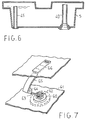
- the tank 5 is provided, additionally to the fill and transfer pipe 40, with an overflow pipe 45, as shown in Figure 6, which also is housed within the tank, with a lower end open into the gutter 20 ( Figure 3) and the upper end open into the tank.
- the pipe 45 in addition to ensuring a maximum level of fill, provides a compensation vent which prevents the tank 5 from becoming pressurized while being filled or vacuumized while being emptied.
- the overflow pipe 45 can be disposed in close proximity of a corner edge of the tank.
- the gutter 20 is also used to advantage for catching any condensation dewdrops formed on the underside of the inner cover 27.
- the programming device which controls the machine operation should include a startup dead time when the pump 14 is operated and any operation of the pressure switch 16 unrecognized, so that, if the tank 5 has been emptied and/or properly placed in its seat, re-start of the machine and the transfer of excess liquid from the pan 13 by pumping into the tank 5 can be allowed.
- the overfill or near-so condition of the tank 5 may advantageously be revealed to the user, even before the stop condition occurs, by a level indicator suitably provided in the tank.
- the liquid level in the tank may be displayed through a clear window formed in the top wall of the tank and perhaps associated with a graduated dipstick inside the tank.
- the tank 5 is mainly laid flat when in the working condition, the use of a more effective display arrangement is preferable.
- Figure 7 is a perspective view showing schematically a preferred embodiment of a maximum level indicator for the tank 5.
- the indicator comprises a plug 60 adhesively attached or thermowelded to the bottom wall 61 of the tank and formed on its interior with a hinge support 62 for a lever 63 which is provided on its end with a buoyant body 64 and a small cylindrically arcuate flag 65 which is facing a clear window 66 formed in the top wall 67 of the tank.
- the hinge support 62 can be formed directly on the lower half-shell, integral therewith.
- the fill and overflow pipes 40 and 45 in Figure 6 may also be moulded in with the lower half-shell.
Landscapes
- Engineering & Computer Science (AREA)
- Textile Engineering (AREA)
- Detail Structures Of Washing Machines And Dryers (AREA)
- Drying Of Solid Materials (AREA)
Claims (11)
- Sèche-linge muni d'un réservoir de collecte de liquide de condensation (5) et d'un dispositif de chargement par le haut au travers d'un couvercle ouvrable (2) et d'une chute de lunette de trou de visite (19) disposée au-dessous de ce couvercle, caractérisé en ce qu'un logement (4) est formé dans l'épaisseur du couvercle (2) afin de recevoir, de manière amovible, le dit réservoir de collecte (5), le logement (4) étant ouvert vers le haut et s'étendant vers le bas au travers de la dite chute de lunette de trou de visite (19).
- Sèche-linge selon la revendication 1, dans lequel le dit réservoir (5) inclut un tuyau de remplissage (40) ouvert au travers d'une paroi inférieure du dit réservoir et s'étendant vers le haut à l'intérieur du dit réservoir (5), et dans lequel le dit bac (4) comporte, dans sa paroi inférieure, au moins une ouverture permettant au dit tuyau de remplissage (40) d'être réuni de façon étroite à un conduit d'évacuation de liquide de condensation (38), à l'intérieur du dit sèche-linge, au traveers de la dite ouverture.
- Sèche-linge selon la revendication 2, incluant un tuyau de trop-plein (45) ouvert au travers de la dite paroi inférieure du réservoir (5) et s'étendant vers le haut à l'intérieur du dit réservoir (5), une goulotte (20) collectant le trop-plein provenant du dit tuyau de trop-plein et étant raccordée par un tuyau de drain (18) à un bac de collecte de liquide de condensation (13) d'un circuit de condensation (10), et une vanne d'isolement (35, (36), 37) sur le dit conduit d'évacuation (38), étant ouverte par la poussée exercée par le dit réservoir (5) reçu dans le dit bac (4) lorsque le dit couvercle se trouve dans la position fermée.
- Sèche-linge selon la revendication 3, dans lequel la dite paroi inférieure (27) du dit bac (4), le couvercle (2) se trouvant dans la dite position fermée, s'incline de façon monotone vers le bas à partir de la position arrière du dit couvercle et en direction de sa partie avant jusqu'à la dite goulotte de collecte de trop-plein (20).
- Sèche-linge selon la revendication 4, comprenant un moyen (51, 52, 53, 54, 75) de maintien de la dite paroi inférieure (27) du bac (4) à l'écart de la dite paroi inférieure du réservoir (5).
- Sèche-linge selon la revendication 5, dans lequel le dit moyen comprend une pluralité de nervures formées sur au moins l'une des dites parois inférieures du couvercle (2) et du réservoir (5).
- Sèche-linge selon la revendication 5, dans lequel le dit moyen comprend deux ailes d'extension (51, 52) du dit réservoir (5) et deux guides de support (53, 54) des dites ailes placées dans le dit couvercle (2).
- Sèche-linge selon les revendications précédentes, dans lequel une trappe d'accès (41) menant à un tambour de sèchage (31) du dit sèche-linge est pourvue d'un joint d'étanchéité résilient (34).
- Sèche-linge selon les revendications précédentes, dans lequel le dit réservoir de collecte (5) inclut un indicateur de niveau de remplissage du type à flotteur (63, 64, 65) opposé à une fenêtre transparente (66) pratiqué dans le dit réservoir (2).
- Sèche-linge selon la revendication 9, dans lequel le dit indicateur de niveau comprend un levier (63) pivotant sur la dite paroi inférieure du réservoir et comportant, à son extrémité libre, un flotteur (64) et un indicateur incurvé de façon cylindrique (65) permettant d'indiquer le niveau.
- Sèche-linge selon les revendications précédentes, dans lequel le dit réservoir de collecte comporte une poignée (51) placée dans une paroi supérieure du dit résercoir (5), à proximité d'une paroi avant du dit réservoir.
Applications Claiming Priority (2)
| Application Number | Priority Date | Filing Date | Title |
|---|---|---|---|
| IT95MI000453A IT1275910B1 (it) | 1995-03-09 | 1995-03-09 | Asciugabiancheria a condensazione con recupero di condensa in contenitore |
| ITMI950453 | 1995-03-09 |
Publications (2)
| Publication Number | Publication Date |
|---|---|
| EP0731204A1 EP0731204A1 (fr) | 1996-09-11 |
| EP0731204B1 true EP0731204B1 (fr) | 2000-05-24 |
Family
ID=11370827
Family Applications (1)
| Application Number | Title | Priority Date | Filing Date |
|---|---|---|---|
| EP95202465A Expired - Lifetime EP0731204B1 (fr) | 1995-03-09 | 1995-09-11 | Sèche-linge à condensation avec dispositif pour receuillir l'eau de condensation dans un conteneur |
Country Status (3)
| Country | Link |
|---|---|
| EP (1) | EP0731204B1 (fr) |
| ES (1) | ES2148423T3 (fr) |
| IT (1) | IT1275910B1 (fr) |
Families Citing this family (10)
| Publication number | Priority date | Publication date | Assignee | Title |
|---|---|---|---|---|
| EP1925712B2 (fr) * | 2006-11-24 | 2017-03-29 | Candy S.p.A. | Séchoir à linge doté de circuits pour limiter la condensation interne |
| DE102007016074A1 (de) | 2007-04-03 | 2008-10-09 | BSH Bosch und Siemens Hausgeräte GmbH | Verfahren und Vorrichtung zum Reinigen eines Bauteiles, insbesondere eines Verdampfers einer Kondensatoreinrichtung sowie Wasch- oder Wäschetrockner mit einer solchen Vorrichtung |
| DE102007049060A1 (de) | 2007-10-12 | 2009-04-16 | BSH Bosch und Siemens Hausgeräte GmbH | Verfahren zum Betreiben einer Spülflüssigkeitseinrichtung in einem Hausgerät zur Pflege von Wäschestücken und Spülflüssigkeitseinrichtung |
| DE102007049061A1 (de) | 2007-10-12 | 2009-04-16 | BSH Bosch und Siemens Hausgeräte GmbH | Verfahren und Vorrichtung zum Reinigen eines Bauteiles, insbesondere eines Verdampfers einer Kondensatoreinrichtung sowie Wasch- oder Wäschetrockner mit einer solchen Vorrichtung |
| KR101467776B1 (ko) * | 2008-04-01 | 2014-12-03 | 엘지전자 주식회사 | 의류처리장치 및 의류처리장치의 제어방법 |
| DE102008032800A1 (de) | 2008-07-11 | 2010-01-14 | BSH Bosch und Siemens Hausgeräte GmbH | Vorrichtung zum Reinigen eines Bauteiles, insbesondere eines Verdampfers einer Kondensatoreinrichtung |
| DE102009001548A1 (de) | 2009-03-13 | 2010-09-16 | BSH Bosch und Siemens Hausgeräte GmbH | Wäschetrocknungsgerät mit einem innerhalb eines Prozessluftkreislaufs angeordneten Flusensieb und Verfahren zum Betreiben des Wäschetrocknungsgeräts |
| DE102011082253A1 (de) * | 2011-09-07 | 2013-03-07 | BSH Bosch und Siemens Hausgeräte GmbH | Wäschetrocknungsgerät |
| EP2610395B1 (fr) * | 2011-12-28 | 2019-07-03 | Electrolux Home Products Corporation N.V. | Réservoir pour liquides pour appareil domestique doté d'une unité d'indication du niveau de liquide |
| KR102620364B1 (ko) | 2017-02-23 | 2024-01-04 | 삼성전자주식회사 | 세탁기 |
Family Cites Families (5)
| Publication number | Priority date | Publication date | Assignee | Title |
|---|---|---|---|---|
| DE2933513C2 (de) * | 1979-08-18 | 1985-08-08 | Miele & Cie GmbH & Co, 4830 Gütersloh | Wäschetrockner mit Kondensationseinrichtung |
| DE3204396C2 (de) * | 1982-02-09 | 1983-12-08 | Bosch-Siemens Hausgeräte GmbH, 7000 Stuttgart | Haushalt-Wäschetrockner mit einem oben angeordneten Kondensat-Sammelbehälter |
| IT211139Z2 (it) * | 1986-07-25 | 1989-02-13 | Zanussi Elettrodomestici | Perfezionamenti alle macchine asciugabiancheria a condensazione. |
| DE3708516A1 (de) * | 1987-03-16 | 1988-09-29 | Bosch Siemens Hausgeraete | Ueberlaufsicherung an einem behaelter, vorzugsweise bei einem waeschetrockner |
| FR2668780B1 (fr) * | 1990-11-02 | 1993-10-22 | Ciapem | Seche-linge se chargeant par le dessus et equipe d'un bac de recuperation de l'eau de sechage. |
-
1995
- 1995-03-09 IT IT95MI000453A patent/IT1275910B1/it active IP Right Grant
- 1995-09-11 ES ES95202465T patent/ES2148423T3/es not_active Expired - Lifetime
- 1995-09-11 EP EP95202465A patent/EP0731204B1/fr not_active Expired - Lifetime
Also Published As
| Publication number | Publication date |
|---|---|
| EP0731204A1 (fr) | 1996-09-11 |
| ITMI950453A1 (it) | 1996-09-09 |
| ITMI950453A0 (it) | 1995-03-09 |
| ES2148423T3 (es) | 2000-10-16 |
| IT1275910B1 (it) | 1997-10-24 |
Similar Documents
| Publication | Publication Date | Title |
|---|---|---|
| EP2155950B1 (fr) | Machine à laver et séchoir | |
| EP0731204B1 (fr) | Sèche-linge à condensation avec dispositif pour receuillir l'eau de condensation dans un conteneur | |
| KR100433777B1 (ko) | 식기 세척 건조기 | |
| CN107260097B (zh) | 清洗机 | |
| EP0767268B1 (fr) | Sèche-linge à condensation et à chargement par le devant ayant un dispositif pour collecter les condensats dans un réservoir détachable | |
| EP0731203B1 (fr) | Sèche-linge à condensation avec dispositif pour recueillir l'eau de condensation dans un conteneur | |
| EP0740012B1 (fr) | Sèche-linge à condensation avec dispositif pour receuillir l'eau de condensation dans un conteneur | |
| US5224508A (en) | Protective automatic dishwashing system | |
| GB2115126A (en) | Household laundry drier with condensate collection | |
| JP5438648B2 (ja) | ドラム式洗濯機 | |
| JP4945537B2 (ja) | 洗濯乾燥機 | |
| EP0463576A1 (fr) | Procédé et installation pour la condensation de l'humidité dans les machines à laver | |
| US8393351B2 (en) | Dual automatic dryer and washing machine protective basin | |
| JP3675367B2 (ja) | 厨芥処理装置 | |
| JP3212839B2 (ja) | 食器洗浄機 | |
| EP3124683B1 (fr) | Seche-linge | |
| KR20080003514A (ko) | 응축식 가정용 음식물 쓰레기 처리기 | |
| JPH0714733Y2 (ja) | 空気調和機 | |
| CN219410273U (zh) | 一种集合废水回收一体的干衣机 | |
| CN219621438U (zh) | 热泵式洗干一体机 | |
| JPS6036231Y2 (ja) | 二槽式洗濯機 | |
| CN208957784U (zh) | 洁净储水盒 | |
| JP3327815B2 (ja) | 業務用炊飯装置 | |
| RU2499092C2 (ru) | Стиральная машина с устройством предотвращения обратного потока | |
| JP3598278B2 (ja) | 洗濯乾燥機 |
Legal Events
| Date | Code | Title | Description |
|---|---|---|---|
| PUAI | Public reference made under article 153(3) epc to a published international application that has entered the european phase |
Free format text: ORIGINAL CODE: 0009012 |
|
| AK | Designated contracting states |
Kind code of ref document: A1 Designated state(s): ES FR IT |
|
| 17P | Request for examination filed |
Effective date: 19960919 |
|
| 17Q | First examination report despatched |
Effective date: 19981029 |
|
| GRAG | Despatch of communication of intention to grant |
Free format text: ORIGINAL CODE: EPIDOS AGRA |
|
| GRAG | Despatch of communication of intention to grant |
Free format text: ORIGINAL CODE: EPIDOS AGRA |
|
| GRAH | Despatch of communication of intention to grant a patent |
Free format text: ORIGINAL CODE: EPIDOS IGRA |
|
| GRAH | Despatch of communication of intention to grant a patent |
Free format text: ORIGINAL CODE: EPIDOS IGRA |
|
| GRAA | (expected) grant |
Free format text: ORIGINAL CODE: 0009210 |
|
| AK | Designated contracting states |
Kind code of ref document: B1 Designated state(s): ES FR IT |
|
| ITF | It: translation for a ep patent filed | ||
| ET | Fr: translation filed | ||
| REG | Reference to a national code |
Ref country code: ES Ref legal event code: FG2A Ref document number: 2148423 Country of ref document: ES Kind code of ref document: T3 |
|
| PLBE | No opposition filed within time limit |
Free format text: ORIGINAL CODE: 0009261 |
|
| STAA | Information on the status of an ep patent application or granted ep patent |
Free format text: STATUS: NO OPPOSITION FILED WITHIN TIME LIMIT |
|
| 26N | No opposition filed | ||
| PGFP | Annual fee paid to national office [announced via postgrant information from national office to epo] |
Ref country code: ES Payment date: 20080807 Year of fee payment: 14 |
|
| PGFP | Annual fee paid to national office [announced via postgrant information from national office to epo] |
Ref country code: IT Payment date: 20080911 Year of fee payment: 14 |
|
| PGFP | Annual fee paid to national office [announced via postgrant information from national office to epo] |
Ref country code: FR Payment date: 20080930 Year of fee payment: 14 |
|
| REG | Reference to a national code |
Ref country code: FR Ref legal event code: ST Effective date: 20100531 |
|
| PG25 | Lapsed in a contracting state [announced via postgrant information from national office to epo] |
Ref country code: FR Free format text: LAPSE BECAUSE OF NON-PAYMENT OF DUE FEES Effective date: 20090930 |
|
| PG25 | Lapsed in a contracting state [announced via postgrant information from national office to epo] |
Ref country code: IT Free format text: LAPSE BECAUSE OF NON-PAYMENT OF DUE FEES Effective date: 20090911 |
|
| REG | Reference to a national code |
Ref country code: ES Ref legal event code: FD2A Effective date: 20110718 |
|
| PG25 | Lapsed in a contracting state [announced via postgrant information from national office to epo] |
Ref country code: ES Free format text: LAPSE BECAUSE OF NON-PAYMENT OF DUE FEES Effective date: 20110706 |
|
| PG25 | Lapsed in a contracting state [announced via postgrant information from national office to epo] |
Ref country code: ES Free format text: LAPSE BECAUSE OF NON-PAYMENT OF DUE FEES Effective date: 20090912 |