EP0731204B1 - A condensation laundry dryer with arrangements for collecting condensation water in a container - Google Patents
A condensation laundry dryer with arrangements for collecting condensation water in a container Download PDFInfo
- Publication number
- EP0731204B1 EP0731204B1 EP95202465A EP95202465A EP0731204B1 EP 0731204 B1 EP0731204 B1 EP 0731204B1 EP 95202465 A EP95202465 A EP 95202465A EP 95202465 A EP95202465 A EP 95202465A EP 0731204 B1 EP0731204 B1 EP 0731204B1
- Authority
- EP
- European Patent Office
- Prior art keywords
- tank
- cover
- dryer
- collecting
- laundry dryer
- Prior art date
- Legal status (The legal status is an assumption and is not a legal conclusion. Google has not performed a legal analysis and makes no representation as to the accuracy of the status listed.)
- Expired - Lifetime
Links
Images


Classifications
-
- D—TEXTILES; PAPER
- D06—TREATMENT OF TEXTILES OR THE LIKE; LAUNDERING; FLEXIBLE MATERIALS NOT OTHERWISE PROVIDED FOR
- D06F—LAUNDERING, DRYING, IRONING, PRESSING OR FOLDING TEXTILE ARTICLES
- D06F39/00—Details of washing machines not specific to a single type of machines covered by groups D06F9/00 - D06F27/00
- D06F39/12—Casings; Tubs
- D06F39/14—Doors or covers; Securing means therefor
-
- D—TEXTILES; PAPER
- D06—TREATMENT OF TEXTILES OR THE LIKE; LAUNDERING; FLEXIBLE MATERIALS NOT OTHERWISE PROVIDED FOR
- D06F—LAUNDERING, DRYING, IRONING, PRESSING OR FOLDING TEXTILE ARTICLES
- D06F58/00—Domestic laundry dryers
- D06F58/20—General details of domestic laundry dryers
- D06F58/24—Condensing arrangements
-
- D—TEXTILES; PAPER
- D06—TREATMENT OF TEXTILES OR THE LIKE; LAUNDERING; FLEXIBLE MATERIALS NOT OTHERWISE PROVIDED FOR
- D06F—LAUNDERING, DRYING, IRONING, PRESSING OR FOLDING TEXTILE ARTICLES
- D06F37/00—Details specific to washing machines covered by groups D06F21/00 - D06F25/00
- D06F37/42—Safety arrangements, e.g. for stopping rotation of the receptacle upon opening of the casing door
Definitions
- This invention relates to a laundry dryer for household use, being of the top-loading type with arrangements for collecting condensation water in a container.
- condensation laundry dryers which do not require to be installed close to a water system connection, and which usually have some rinse, cooling or condensation water draining arrangements associated therewith, since steam (not to be released to the environment) is caused to condensate from the drying process therein by a stream of cooling air.
- Such machines include of necessity a condensate collecting tank whose capacity is at least equal to the volume of condensate produced by one drying cycle when in maximum load conditions and which requires to be emptied periodically, so that it must be provided detachable.
- the tank is taken out through a front door in the machine by a horizontal sliding movement.
- a further disadvantage comes from the liquid being possibly spilled out of the condensation water collecting tank housing compartment, open to the front.
- Front loading laundry dryers have also been provided with the tank placed in the upper area of the machine, inside an open front compartment whence the tank can be slid out. This does make for easier tank handling and water level checking, but is at clash with the consumer's aesthetic demands and cannot provide full protection against overflow and spillage, just as when the tank is installed in the lower area.
- top loading machines i.e. machines having no front doors
- machines having no front doors have been proposed which have the tank placed between the machine top cover and the rotating laundry-drying basket (see EP-A-0 484 225).
- the tank be provided with automatic closure tight fittings for connection to a condensate delivery line.
- the flat cover must be a significant thickness and formed of an outer cover and inner cover separated by a suitable gap in the 2 to 3 cm range.
- This volume may amount to a few liters, and represents an unnecessary waste.
- the present invention obviates all these drawbacks and provides a top loading laundry dryer with collecting tank for the condensation water, wherein the cover top is provided with a housing for a collecting tank to be placed removably into the housing with a flat top surface coplanar with the cover top surface.
- the housing is provided with two openings in its lower portion to enable the tank to be joined to an intake valving system and an overflow collecting means.
- the valving system is conveniently constructed to cut off any flow of condensate to the tank if the latter is not there or does not fit properly in its housing.
- the valving system is mounted in a gutter for catching any overflowing liquid or condensation dewdrops and recirculate them to the condensation circuit, thereby providing double protection against any liquid spill to the machine interior.
- the gutter is conveniently formed in the handhole bezel with which top loading dryers come inherently equipped.
- the collecting tank is provided with an internal intake conduit which is open at the top and communicated to the outside at the bottom for its connection to the valving system, and with an internal overflow conduit which also is open at the top and communicated to the outside at the bottom to discharge any overflow into the gutter.
- the two intake and overflow conduits are disposed near a front wall of the tank, which wall forms a handgrip for pulling the tank out of its housing which is offset from the tank center of gravity under any fill conditions.
- the tank housing in the cover is closed at the bottom by an inner cover wall having a monotonic downward slope from a rear portion of the machine toward the front thereof and to the overflow and condensate collecting gutter.
- the drum loading door is provided with a resilient sealing gasket.
- the tank is provided with a float type of level indicator.
- FIG. 1 shown therein is an exploded overall perspective view of a laundry dryer embodying the present invention.
- the dryer is compact in size and comprises a box-type body 1, generally of enamelled sheet metal, in the form of a right parallelepipedon having a depth P, illustratively of 60 cm, height H of 85 cm, and width L of 40 cm.
- Depth and width refer to the normal conditions of installation and use anticipated.
- the box-type body 1 is closed at the top by a cover 2, which can be swung open about a hinge 3 located near the rear corner edge of the body, on which a known control and program panel 74 locates.
- the box-type body conventionally accommodates a cylindrical drum (not shown in the FIgure) rotating about a horizontal axis and being provided on its periphery with an unlockable door made accessible by opening the cover 2, through which laundry is introduced into the rotating drum or basket for drying.
- the drum illustratively has a diameter such that most of the box-type body inside volume is occupied by the drum which, for easy introduction of the laundry, should be placed with its peripheral top as close as possible to the cover.
- a rectangular hoousing 4 is formed in the cover thickness which is closed downwardly by an inner cover 27 which extends into the box-type body down to a suitable depth limited by the space requirements of the rotating drum.
- a collecting tank 5 for the condensation liquid is accommodated removably in the housing 4.
- the housing 4 and tank 5 are suitably shaped to make best use of the available interior volume of the machine.
- the tank 5 is suitably provided, near the front wall 6 of the machine body, with a handgrip 51 for removing it and a lens 52 or clear window to view its fill level therethrough.
- a ventilation grid which allows cooling air for an internal condenser to be drawn in (or even blown out).
- suction or ejection could take place through the machine bottom, if the latter is raised off the floor on rest feet, but with the inflow and outflow substantially separated from each other.
- a heat exchanger/steam condenser Provided in the lower portion of the box-type body, not shown in Figure 1, are a heat exchanger/steam condenser, a condensation fluid collecting pan, and motive members for driving rotatively the drum, suction fans and a condensation liquid transfer pump.
- FIG. 1 shows in block diagram form the construction of the laundry dryer of Figure 1.
- a stream of heated air is flowed in a closed loop through the drum 31, it being admitted through a side wall 7 or tympan end of the drum and discharged through the opposite wall 8.
- the heated air vaporizes the liquid with which the laundry is soaked.
- the stream is induced by a fan 9 which directs the moisture-laden warm air into a heat exchanger/condenser 10.
- the exchanger is crossed, in counterflow or crossflow relationship, by a stream of cool air, drawn in from the environment, induced by a fan 11, so that the moist warm air is cooled and moisture condensed in the exchanger.
- the moisture-free cool air is introduced, in closed loop circulation, back into the drum 31 after being heated by electric resistance heaters 12, while the heated condensation air is exhausted to the environment.
- the condensation liquid which forms in the heat exchanger is discharged to a collecting pan 13, which may be integral with the condenser, and by means of a pump 14 is directed into the collecting tank 5 for the liquid through a safety valve device 53 to be explained.
- the operation of the laundry dryer is controlled by a programmer 15 which operates the various electric and mechanical members and detects the liquid level in the pan 13 by means of a pressure switch 16 or an equivalent sensor, to cease operation on the occurrence of anomalous conditions, such as the pan 13 becoming overfilled.
- the inner cover 27 which closes the bottom of the housing 4 for the condensation liquid collecting tank 5 is suitably connected to an overflow and condensation dewdrop collecting pan 17 which discharges any overflow and condensate to the pan 13, preferably under a head where the pan 13 is in communication with the air of the drying circuit, through a drain conduit 18.
- Figure 3 is a front-to-rear sectional view of the upper portion of the laundry dryer to bring out some of its constructional details.
- the box-type body 1 is provided at the top with a handhole bezel 19, preferably a plastics moulding, having at its center a rectangular access slip to provide access to the drying drum, with walls which lead funnel-like on four sides to a location close to the outer surface of the drum 31.
- a handhole bezel 19 preferably a plastics moulding, having at its center a rectangular access slip to provide access to the drying drum, with walls which lead funnel-like on four sides to a location close to the outer surface of the drum 31.
- the handhole bezel is sunk into the box-type body to form a gutter 20 for collecting overflow from the tank 5.
- the gutter is provided with a drain port 23 which is connected to the condensation liquid collecting pan by a pipe 24.
- Hinged to the handhole bezel on the rearward side thereof, is a cover which closes the box-type body top and the access slip formed by the handhole bezel 19.
- the cover also is a box-type construction formed of a flat top frame or cover 26 of enamelled sheet metal, bounding a rectangular opening, and a bottom wall or inner cover 27 of moulded plastics.
- the inner cover is not flat but has a central zone which is sunk into the handhole bezel slip 19 and merges with the walls of the latter to form a housing 4, which is rectangular in plan view and open upwardly, for the tank 5 which is inserted thereinto through the cover opening.
- the bottom wall of the central zone of the inner cover is inclined with a monotonic downward slope from the rear portion to the front portion.
- the front edge of the cover is completed by a molded plastics grille 21 which is expediently formed with a handle for opening the cover.
- the drying drum 31 is conventionally provided with a door 41 hinged about a generatrix line 32 of the drum.
- the door 41 is conventionally provided with an opening handle 33 which also functions as a lock when in the closed position.
- the door 41 is provided with a resilient lip seal 34 to ensure a substantially tight fit between the door 41 and the drum 31.
- snap-action holding devices may be suitably arranged to act between tank and the cover without affecting the ease of removal thereof.
- the tank 5 withdrawal is particularly ergonomic because the tank can be grasped near the front at standard working surface level.
- the inner cover provides a bearing surface for the rear edge of the tank, which can be raised partially and effortlessly with its front portion and slid on the inner cover with its rear portion such that the tank volume will move toward the front and the operator. In this position, the whole tank can be raised without reach and is extremely facilitated.
- the sides of the drum mounted for rotation about a center shaft, are perforated near the shaft to admit heated air into the drum and exhaust moisture-laden air from the drum.
- the drying air delivery and return channels are connected to the drum by means of seals, preferably labyrinth seals, whose fit is less than perfect, so that a minimal volume of relatively moist warm air is let out past the seals.
- This motion has the pattern shown by arrows 36, when the drum 3 is turning with its top in the direction of arrow 35.
- this problem is substantially obviated by the inner cover interposed between the tank and the stream of moist air forming an effective thermal insulation shield which allows the inner cover to become heated by the heat transferred by the convective motion of the air inside the slip, with but minimal leakage to the tank.
- the direct contact of the bottom wall of the inner cover with the tank can be minimized by providing elongate ribs in a front-to-rear direction, for example, either across the wall of the inner cover or the juxtaposed one of the tank, so that an air space is left therebetween which has a thickness on the order of few millimeters and excellent exterior sound as well as thermal insulation can be provided.
- ribs 75 formed on the inner cover, at the bottom of the housing 4. This largely obviates the formation of condensation water on the wall under the inner cover.
- Figure 4 shows an exploded perpspective view of an embodiment which achieves the same spacing and interspace formation effect between the inner cover and the tank bottom while enabling the tank 5 capacity to be maximized.
- the tank 5 is provided with two expansion wings 51, 52 which extend along the tank sides flush with its top wall.
- the wings are received within the cover thickness and bear on two side guides 53, 54 set in the inner cover.
- the bottom wall 55 of the tank can be held off the bottom 56 of the housing formed by the inner cover, and the tank capacity be concurrently increased by the volumes of the wings which act as floodplains for tank overfill conditions.
- Figure 5 is a sectional view in the machine front-to-rear direction of a preferred embodiment of the intake valving system 53 for filling the collecting tank, and shows in greater detail the relative arrangement of the tank, the inner cover, and the handhole bezel.
- a cylindrical sleeve 22 Formed in the handhole bezel 19, inwards of the collecting gutter 20, is a cylindrical sleeve 22 having an inside shoulder 25 and being coaxial with a cylindrical sleeve 28 which depends from the gutter 20.
- the sleeve 28 is also provided with an inside shoulder 29.
- the sleeve 28 receives slidably, axially therein, a tubular element 30 which is closed at its lower end by a plug 35 and extends upwardly into the sleeve 22.
- the lower end of the tubular element 30 is provided with a resilient sealing gasket 43, such as an O-ring.
- the tubular element 30 is provided with an outside flange 36 received slidably in the sleeve 22.
- a compression spring 37 is mounted between the tubular element 30 and the sleeve 22, and acts between the shoulder 25 and the flange 36 to bias the tubular element 30 upwards to a rest position defined by the gasket 43 coming into sealing contact with the shoulder 29.
- the annular element 30 acts as a closed shut-off valve for a stream of condensation water conveyed into the sleeve 28 through a delivery pipe 38.
- the tank 5 Located in the housing 4 is the tank 5, which is provided on its interior with a condensation liquid transfer pipe 40 which is aligned axially to the tubular element 30.
- the pipe 40 has an open top end near the top wall of the tank 5 and flares out at its bottom end into a coupling flange 41 for glued or thermowelded attachment to the bottom wall of the tank 5, as suitably apertured for the insertion of the pipe 40 into the tank.
- the flange 41 also forms a conical fitting for connection to the top end of the tubular element 30, which may be suitably provided with a sealing gasket 42.
- the flange 41 will interfere with the upper end of the tubular element 30 and move it a predetermined distance axially downwards against the bias force of the spring 37.
- the bottom end of the element 30 is provided with radial openings 44 in its peripheral surface which open into the sleeve 28 interior.
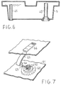
- the tank 5 is provided, additionally to the fill and transfer pipe 40, with an overflow pipe 45, as shown in Figure 6, which also is housed within the tank, with a lower end open into the gutter 20 ( Figure 3) and the upper end open into the tank.
- the pipe 45 in addition to ensuring a maximum level of fill, provides a compensation vent which prevents the tank 5 from becoming pressurized while being filled or vacuumized while being emptied.
- the overflow pipe 45 can be disposed in close proximity of a corner edge of the tank.
- the gutter 20 is also used to advantage for catching any condensation dewdrops formed on the underside of the inner cover 27.
- the programming device which controls the machine operation should include a startup dead time when the pump 14 is operated and any operation of the pressure switch 16 unrecognized, so that, if the tank 5 has been emptied and/or properly placed in its seat, re-start of the machine and the transfer of excess liquid from the pan 13 by pumping into the tank 5 can be allowed.
- the overfill or near-so condition of the tank 5 may advantageously be revealed to the user, even before the stop condition occurs, by a level indicator suitably provided in the tank.
- the liquid level in the tank may be displayed through a clear window formed in the top wall of the tank and perhaps associated with a graduated dipstick inside the tank.
- the tank 5 is mainly laid flat when in the working condition, the use of a more effective display arrangement is preferable.
- Figure 7 is a perspective view showing schematically a preferred embodiment of a maximum level indicator for the tank 5.
- the indicator comprises a plug 60 adhesively attached or thermowelded to the bottom wall 61 of the tank and formed on its interior with a hinge support 62 for a lever 63 which is provided on its end with a buoyant body 64 and a small cylindrically arcuate flag 65 which is facing a clear window 66 formed in the top wall 67 of the tank.
- the hinge support 62 can be formed directly on the lower half-shell, integral therewith.
- the fill and overflow pipes 40 and 45 in Figure 6 may also be moulded in with the lower half-shell.
Description
- This invention relates to a laundry dryer for household use, being of the top-loading type with arrangements for collecting condensation water in a container.
- Known are condensation laundry dryers which do not require to be installed close to a water system connection, and which usually have some rinse, cooling or condensation water draining arrangements associated therewith, since steam (not to be released to the environment) is caused to condensate from the drying process therein by a stream of cooling air.
- Such machines include of necessity a condensate collecting tank whose capacity is at least equal to the volume of condensate produced by one drying cycle when in maximum load conditions and which requires to be emptied periodically, so that it must be provided detachable.
- Several alternative constructions have been proposed and used. In many instances the tank has been placed in the lower area of the laundry dryer at a lower level than the condenser, such that the condensation water would flow into the collecting tank by gravity without pump assistance.
- The tank is taken out through a front door in the machine by a horizontal sliding movement.
- This solution is economical but has some disadvantages: the tank is awkward to remove, from an ergonomic standpoint, and is not safeguarded against spillage when overfilled.
- While the problem may be overcome by having the level of fill displayed, a visual check of the level would still be inconvenient to effect.
- Viable automatic arrangements for monitoring the filled up and overflow state would be expensive and additional to the protection arrangements already made to ensure the laundry dryer general operability.
- A further disadvantage comes from the liquid being possibly spilled out of the condensation water collecting tank housing compartment, open to the front.
- Front loading laundry dryers have also been provided with the tank placed in the upper area of the machine, inside an open front compartment whence the tank can be slid out. This does make for easier tank handling and water level checking, but is at clash with the consumer's aesthetic demands and cannot provide full protection against overflow and spillage, just as when the tank is installed in the lower area.
- Furthermore, top loading machines, i.e. machines having no front doors, have been proposed which have the tank placed between the machine top cover and the rotating laundry-drying basket (see EP-A-0 484 225).
- This is an attractive solution, but has a drawback in that a large proportion of the tank surface is left exposed to the heated, relatively moisture-laden air which would surround the basket in the event of the drying circuit being made less than perfectly tight. This surface is bound to act as a particularly active condensing surface and to significantly degrade the machine efficiency.
- Since the tank undersurface next to the dryer drum is cylindrically concave, the risk exists of an amount of condensate building up by gravity in the lowermost area thereof, with the result that water may drip onto the drum and be scattered around the dryer body interior to initiate corrosive processes on any inadequately protected metal and electric parts.
- From the engineering standpoint, moreover, it is necessary that the tank be provided with automatic closure tight fittings for connection to a condensate delivery line.
- Another drawback of this approach is that, with the tank accommodated inside, its fill level cannot be checked from the outside, this operation requiring that the cover be lifted up.
- And even so, the level is difficult to reveal conveniently.
- Finally, the limited room available cannot be exploited to its best, because for strength reasons, the flat cover must be a significant thickness and formed of an outer cover and inner cover separated by a suitable gap in the 2 to 3 cm range.
- This volume may amount to a few liters, and represents an unnecessary waste.
- The present invention obviates all these drawbacks and provides a top loading laundry dryer with collecting tank for the condensation water, wherein the cover top is provided with a housing for a collecting tank to be placed removably into the housing with a flat top surface coplanar with the cover top surface.
- The housing is provided with two openings in its lower portion to enable the tank to be joined to an intake valving system and an overflow collecting means.
- The valving system is conveniently constructed to cut off any flow of condensate to the tank if the latter is not there or does not fit properly in its housing.
- This in order to provide the apparatus with maximum protection against any leakout of liquid.
- According to a further aspect of the present invention, the valving system is mounted in a gutter for catching any overflowing liquid or condensation dewdrops and recirculate them to the condensation circuit, thereby providing double protection against any liquid spill to the machine interior. The gutter is conveniently formed in the handhole bezel with which top loading dryers come inherently equipped.
- According to a further aspect of the present invention, the collecting tank is provided with an internal intake conduit which is open at the top and communicated to the outside at the bottom for its connection to the valving system, and with an internal overflow conduit which also is open at the top and communicated to the outside at the bottom to discharge any overflow into the gutter.
- According to a further aspect of the present invention, the two intake and overflow conduits are disposed near a front wall of the tank, which wall forms a handgrip for pulling the tank out of its housing which is offset from the tank center of gravity under any fill conditions.
- In this way, the removal of the tank is effected by a rotation of the same and with the condensation liquid contained therein displaced to the bottom rear of the tank, away from the intake and overflow conduits, thereby eliminating all risks of spillage in handling the tank.
- According to a further aspect of the present invention, the tank housing in the cover is closed at the bottom by an inner cover wall having a monotonic downward slope from a rear portion of the machine toward the front thereof and to the overflow and condensate collecting gutter.
- According to a further aspect of the present invention, to enhance drying efficiency and minimize condensation phenomena over the interior walls of the dryer, the drum loading door is provided with a resilient sealing gasket.
- According to a further aspect of the present invention, the tank is provided with a float type of level indicator.
- The features and advantages of the present invention will become apparent from the following description and the accompanying drawings, in which:
- Figure 1 is an overall perspective view of a laundry dryer embodying the present invention;
- Figure 2 is a functional diagram of the architecture of a laundry dryer embodying the present invention;
- Figure 3 is a fragmentary front-to-rear section view of the laundry dryer in Figure 1;
- Figure 4 is an exploded perspective view of a modified embodiment of the laundry dryer according to the present invention;
- Figure 5 is a front-to-rear section view of a preferred embodiment of a tank fill valving system according to the present invention;
- Figure 6 is a sectional view of the collecting tank along I-I in Figure 5;
- Figure 7 is a perspective view showing schematically a preferred embodiment of a level indicator for the laundry dryer in Figure 1.
-
- Referring to Figure 1, shown therein is an exploded overall perspective view of a laundry dryer embodying the present invention.
- The dryer is compact in size and comprises a box-
type body 1, generally of enamelled sheet metal, in the form of a right parallelepipedon having a depth P, illustratively of 60 cm, height H of 85 cm, and width L of 40 cm. - Depth and width refer to the normal conditions of installation and use anticipated.
- The box-
type body 1 is closed at the top by acover 2, which can be swung open about a hinge 3 located near the rear corner edge of the body, on which a known control and program panel 74 locates. - The box-type body conventionally accommodates a cylindrical drum (not shown in the FIgure) rotating about a horizontal axis and being provided on its periphery with an unlockable door made accessible by opening the
cover 2, through which laundry is introduced into the rotating drum or basket for drying. - The drum illustratively has a diameter such that most of the box-type body inside volume is occupied by the drum which, for easy introduction of the laundry, should be placed with its peripheral top as close as possible to the cover. A
rectangular hoousing 4 is formed in the cover thickness which is closed downwardly by aninner cover 27 which extends into the box-type body down to a suitable depth limited by the space requirements of the rotating drum. - A
collecting tank 5 for the condensation liquid is accommodated removably in thehousing 4. - As explained hereinafter, the
housing 4 andtank 5 are suitably shaped to make best use of the available interior volume of the machine. Thetank 5 is suitably provided, near thefront wall 6 of the machine body, with ahandgrip 51 for removing it and alens 52 or clear window to view its fill level therethrough. - Mounted in the lower portion of the
front wall 6 is a ventilation grid which allows cooling air for an internal condenser to be drawn in (or even blown out). - Alternatively, the suction or ejection could take place through the machine bottom, if the latter is raised off the floor on rest feet, but with the inflow and outflow substantially separated from each other.
- Provided in the lower portion of the box-type body, not shown in Figure 1, are a heat exchanger/steam condenser, a condensation fluid collecting pan, and motive members for driving rotatively the drum, suction fans and a condensation liquid transfer pump.
- Figure 2 shows in block diagram form the construction of the laundry dryer of Figure 1.
- A stream of heated air is flowed in a closed loop through the
drum 31, it being admitted through aside wall 7 or tympan end of the drum and discharged through theopposite wall 8. The heated air vaporizes the liquid with which the laundry is soaked. - The stream is induced by a
fan 9 which directs the moisture-laden warm air into a heat exchanger/condenser 10. - The exchanger is crossed, in counterflow or crossflow relationship, by a stream of cool air, drawn in from the environment, induced by a
fan 11, so that the moist warm air is cooled and moisture condensed in the exchanger. - The moisture-free cool air is introduced, in closed loop circulation, back into the
drum 31 after being heated byelectric resistance heaters 12, while the heated condensation air is exhausted to the environment. - The condensation liquid which forms in the heat exchanger is discharged to a collecting
pan 13, which may be integral with the condenser, and by means of apump 14 is directed into thecollecting tank 5 for the liquid through asafety valve device 53 to be explained. - The operation of the laundry dryer is controlled by a
programmer 15 which operates the various electric and mechanical members and detects the liquid level in thepan 13 by means of apressure switch 16 or an equivalent sensor, to cease operation on the occurrence of anomalous conditions, such as thepan 13 becoming overfilled. - Other safety devices, not shown, e.g. related to the closed state of the
cover 2, may be suitably provided. - Advantageously, the
inner cover 27 which closes the bottom of thehousing 4 for the condensation liquid collectingtank 5 is suitably connected to an overflow and condensationdewdrop collecting pan 17 which discharges any overflow and condensate to thepan 13, preferably under a head where thepan 13 is in communication with the air of the drying circuit, through adrain conduit 18. - The importance of the collecting
pan 17 and itsdrain connection 18 to thepan 13 will be explained hereinafter. - Figure 3 is a front-to-rear sectional view of the upper portion of the laundry dryer to bring out some of its constructional details.
- The box-
type body 1 is provided at the top with ahandhole bezel 19, preferably a plastics moulding, having at its center a rectangular access slip to provide access to the drying drum, with walls which lead funnel-like on four sides to a location close to the outer surface of thedrum 31. - In the vicinity of the
front wall 6, the handhole bezel is sunk into the box-type body to form agutter 20 for collecting overflow from thetank 5. - The gutter is provided with a
drain port 23 which is connected to the condensation liquid collecting pan by apipe 24. - Hinged to the handhole bezel, on the rearward side thereof, is a cover which closes the box-type body top and the access slip formed by the
handhole bezel 19. - Expediently, the cover also is a box-type construction formed of a flat top frame or cover 26 of enamelled sheet metal, bounding a rectangular opening, and a bottom wall or
inner cover 27 of moulded plastics. The inner cover is not flat but has a central zone which is sunk into thehandhole bezel slip 19 and merges with the walls of the latter to form ahousing 4, which is rectangular in plan view and open upwardly, for thetank 5 which is inserted thereinto through the cover opening. - Expediently for reasons to be discussed, the bottom wall of the central zone of the inner cover is inclined with a monotonic downward slope from the rear portion to the front portion.
- The front edge of the cover is completed by a molded
plastics grille 21 which is expediently formed with a handle for opening the cover. - The drying
drum 31 is conventionally provided with adoor 41 hinged about ageneratrix line 32 of the drum. Thedoor 41 is conventionally provided with anopening handle 33 which also functions as a lock when in the closed position. - Advantageously, but not necessarily, the
door 41 is provided with aresilient lip seal 34 to ensure a substantially tight fit between thedoor 41 and thedrum 31. - It will be appreciated from Figure 3 that, with the cover opened, the slip formed by the handhole bezel is freed internally so that the
door 41 can be opened to introduce laundry or withdraw dried items from thedrum 31, with no need to first remove thetank 5 from its housing in the cover. - To prevent the tank from incidentally coming out of its housing when the cover is open wide by a rotation somewhat in excess of 90°, snap-action holding devices may be suitably arranged to act between tank and the cover without affecting the ease of removal thereof.
- The
tank 5 withdrawal is particularly ergonomic because the tank can be grasped near the front at standard working surface level. In addition, the inner cover provides a bearing surface for the rear edge of the tank, which can be raised partially and effortlessly with its front portion and slid on the inner cover with its rear portion such that the tank volume will move toward the front and the operator. In this position, the whole tank can be raised without reach and is extremely facilitated. - Before discussing further advantageous expedients contemplated by the invention, it pays to consider some major technical problems solved by the invention.
- As previously mentioned, the sides of the drum, mounted for rotation about a center shaft, are perforated near the shaft to admit heated air into the drum and exhaust moisture-laden air from the drum.
- The drying air delivery and return channels are connected to the drum by means of seals, preferably labyrinth seals, whose fit is less than perfect, so that a minimal volume of relatively moist warm air is let out past the seals.
- To this, there may add moist air leaking past the
loading door 41 to the basket outside. - The relatively moist warm air which surrounds the drum, due to friction against the walls, is dragged around and centrifuged toward the drum periphery.
- Thus, an airflow is created at the drum periphery which generates convective motion in the space between the drum and the cover, within the handhole bezel slip (19).
- This motion has the pattern shown by
arrows 36, when the drum 3 is turning with its top in the direction ofarrow 35. - The presence of a condensation liquid collecting tank, at room temperature and with large heat capacity, due to the liquid contained therein, with a cold wall in contact with the convective flow, as proposed by the state of the art, causes dewdrops to form on the bottom wall of the tank which fall onto the drum during the drying operation and are dragged around by the drum and scattered all over the interior parts of the machine to cause the aforementioned problems. Also, on completion of the drying process, it may cause dripping outside the machine as the tank is manipulated for removal.
- By converse, in the embodiment of Figure 3, this problem is substantially obviated by the inner cover interposed between the tank and the stream of moist air forming an effective thermal insulation shield which allows the inner cover to become heated by the heat transferred by the convective motion of the air inside the slip, with but minimal leakage to the tank. To this aim, the direct contact of the bottom wall of the inner cover with the tank can be minimized by providing elongate ribs in a front-to-rear direction, for example, either across the wall of the inner cover or the juxtaposed one of the tank, so that an air space is left therebetween which has a thickness on the order of few millimeters and excellent exterior sound as well as thermal insulation can be provided.
- Shown for example in Figure 1 are
ribs 75 formed on the inner cover, at the bottom of thehousing 4. This largely obviates the formation of condensation water on the wall under the inner cover. - It should also be noted that, thanks to the particular shape of the inner cover with the bottom wall sloping frontally downwards, even in the event of dewdrops being formed as a result of some anomalous leakouts of moisture-laden air from the drying circuit or of splashes caused by the basket rotation, these will tend, by the combined effects of gravity and the mechanical convective action, to move toward the front wall of the inner cover where, by aggregating into larger volume drops, they tend to drip into the
gutter 20 wherefrom they are then picked up. - Figure 4 shows an exploded perpspective view of an embodiment which achieves the same spacing and interspace formation effect between the inner cover and the tank bottom while enabling the
tank 5 capacity to be maximized. - As shown in Figure 4, the
tank 5 is provided with twoexpansion wings - In this way, the
bottom wall 55 of the tank can be held off the bottom 56 of the housing formed by the inner cover, and the tank capacity be concurrently increased by the volumes of the wings which act as floodplains for tank overfill conditions. - Figure 5 is a sectional view in the machine front-to-rear direction of a preferred embodiment of the
intake valving system 53 for filling the collecting tank, and shows in greater detail the relative arrangement of the tank, the inner cover, and the handhole bezel. - Formed in the
handhole bezel 19, inwards of the collectinggutter 20, is acylindrical sleeve 22 having aninside shoulder 25 and being coaxial with acylindrical sleeve 28 which depends from thegutter 20. - The
sleeve 28 is also provided with aninside shoulder 29. - The
sleeve 28 receives slidably, axially therein, atubular element 30 which is closed at its lower end by aplug 35 and extends upwardly into thesleeve 22. - The lower end of the
tubular element 30 is provided with aresilient sealing gasket 43, such as an O-ring. - At an intermediate axial location, the
tubular element 30 is provided with anoutside flange 36 received slidably in thesleeve 22. - A
compression spring 37 is mounted between thetubular element 30 and thesleeve 22, and acts between theshoulder 25 and theflange 36 to bias thetubular element 30 upwards to a rest position defined by thegasket 43 coming into sealing contact with theshoulder 29. - In this position, the
annular element 30 acts as a closed shut-off valve for a stream of condensation water conveyed into thesleeve 28 through adelivery pipe 38. - With the machine
inner cover 27 closed, its bottom wall, which forms the bottom of thehousing 4, will be facing the end of thesleeve 22, and is provided with acircular opening 39 coaxial with thesleeve 22 to allow the upper end of thetubular element 30 to be led through with ample clearance. - Located in the
housing 4 is thetank 5, which is provided on its interior with a condensationliquid transfer pipe 40 which is aligned axially to thetubular element 30. - The
pipe 40 has an open top end near the top wall of thetank 5 and flares out at its bottom end into acoupling flange 41 for glued or thermowelded attachment to the bottom wall of thetank 5, as suitably apertured for the insertion of thepipe 40 into the tank. - The
flange 41 also forms a conical fitting for connection to the top end of thetubular element 30, which may be suitably provided with a sealinggasket 42. - With the
tank 5 properly fitted in its cover housing, and the cover closed, theflange 41 will interfere with the upper end of thetubular element 30 and move it a predetermined distance axially downwards against the bias force of thespring 37. - The bottom end of the
element 30 is provided withradial openings 44 in its peripheral surface which open into thesleeve 28 interior. - In this way, the tightness of the element 30-to-
flange 41 fit is ensured, on the one side, while on the other side, the shut-off valve is controlled to open, by the pressure from thespring 37. - It can be appreciated that, absent the
tank 5 or with the cover not perfectly closed, the shut-off valve would stay closed. - The
tank 5 is provided, additionally to the fill and transferpipe 40, with anoverflow pipe 45, as shown in Figure 6, which also is housed within the tank, with a lower end open into the gutter 20 (Figure 3) and the upper end open into the tank. - The
pipe 45, in addition to ensuring a maximum level of fill, provides a compensation vent which prevents thetank 5 from becoming pressurized while being filled or vacuumized while being emptied. - Advantageously as shown in Figure 6, to ensure that the tank can be virtually completely emptied without requiring the provision of removable plugs, the
overflow pipe 45 can be disposed in close proximity of a corner edge of the tank. - Any spillouts through the
overflow pipe 45, with the tank installed in its housing, would fall into thegutter 20 and be discharged into the condensation water collecting pan 13 (Figure 2). - The
gutter 20 is also used to advantage for catching any condensation dewdrops formed on the underside of theinner cover 27. - For this purpose, it can be seen in Figure 5 that the bottom plate of the inner cover, sloping monotonically downwards, is terminated in its closest zone to the machine front with a depending
rib 46 and received in thegutter 20 which acts as a drip sprinkler and on which any condensation water formed on the underside of the inner cover collects by gravity. - Before taking into consideration other advantageous detailed aspects of the tank, it pays to close with the discussion of some functional aspects mentioned above.
- Prior art laundry dryers equipped with a collecting tank have been said to require inherent protection to discontinue the machine operation on the occurrence of an overfill condition of the tank.
- To provide this protection, devices have been proposed which are either responsive to the tank weight or the level of the liquid therein to operate warning and stop electric switches, additional to the protection devices and consisting of the pressure switch 16 (Figure 2) which controls the level of the liquid in the collecting
pan 13, perhaps provided integral with theexchanger 10. - In the laundry dryer of the present invention, these additional protective devices are unnecessary and their function is performed by the
pressure switch 16. - This is made possible by the return conduit 18 (Figure 2) draining any overflows from the
tank 5 into thepan 13. It is apparent that if an overfill condition of thetank 5 occurs and the volume of the condensation liquid increases due to a drying operation being carried out, the level in the collectingpan 13 will rise causing thepressure switch 16 to be operated and stop the machine. The protection also operates in the event that thetank 5 is not there. In this case, the shut-off valve formed by theelement 30 would stay closed and thetank loading pump 14 turn idle and the condensation liquid build up in thepan 13. - It is apparent that to avoid permanent shutdowns of the machine, the programming device which controls the machine operation should include a startup dead time when the
pump 14 is operated and any operation of thepressure switch 16 unrecognized, so that, if thetank 5 has been emptied and/or properly placed in its seat, re-start of the machine and the transfer of excess liquid from thepan 13 by pumping into thetank 5 can be allowed. - The overfill or near-so condition of the
tank 5 may advantageously be revealed to the user, even before the stop condition occurs, by a level indicator suitably provided in the tank. - The liquid level in the tank may be displayed through a clear window formed in the top wall of the tank and perhaps associated with a graduated dipstick inside the tank.
- However, since the
tank 5 is mainly laid flat when in the working condition, the use of a more effective display arrangement is preferable. - Figure 7 is a perspective view showing schematically a preferred embodiment of a maximum level indicator for the
tank 5. - The indicator comprises a
plug 60 adhesively attached or thermowelded to thebottom wall 61 of the tank and formed on its interior with ahinge support 62 for alever 63 which is provided on its end with abuoyant body 64 and a small cylindricallyarcuate flag 65 which is facing aclear window 66 formed in the top wall 67 of the tank. - It is apparent that, according to the liquid level in the tank and hence to the float position, the lever will adopt a predetermined angular position which is corresponded by the showing of a predetermined arc of the flag through the window.
- In this way, the tank level of fill can be immediately evaluated with good accuracy.
- Also apparent is that, where the
collecting tank 5 is formed of two half-shells coupled together instead of being a unitary blown piece, thehinge support 62 can be formed directly on the lower half-shell, integral therewith. In this case, the fill andoverflow pipes
Claims (11)
- A laundry dryer with a condensation liquid collecting tank (5) and top loading facilities through an openable cover (2) and a handhole bezel slip (19) underlying the cover, characterized in that a housing (4) is formed in the cover (2) thickness for removably accomodating said collecting tank (5), the housing (4) being open upwardly and extending downwardly through said handhole bezel slip (19).
- The laundry dryer of Claim 1, wherein said tank (5) includes a fill pipe (40) open through a bottom wall of said tank and extending upwards inside said tank (5), and wherein said pan (4) is provided, in a bottom wall thereof, with at least one opening to enable said fill pipe (40) to be joined tightly to a condensation liquid delivery conduit (38), inside said laundry dryer, through said opening.
- The laundry dryer of Claim 2, including an overflow pipe (45) open through said bottom wall of the tank (5) and extending upwards within said tank (5), a gutter (20) collecting overflow from said overflow pipe and being connected by a drain pipe (18) to a condensation liquid collecting pan (13) of a condensation circuit (10), and a shut-off valve (35,(36),37) in said delivery conduit (38), being opened by the thrust exerted by said tank (5) accommodated in said pan (4) when said cover is in the closed position.
- The laundry dryer of Claim 3, wherein said bottom wall (27) of said pan (4), with the cover (2) in said closed position, slopes monotonically downwards from the rear portion of said cover and toward its front portion to said overflow collecting gutter (20).
- The laundry dryer of Claim 4, comprising a means (51,52,53,54,75) of holding said pan (4) bottom wall (27) off said tank (5) bottom wall.
- The dryer of Claim 5, wherein said means comprises a plurality of ribs formed on at least one of said bottom walls of the cover (2) and the tank (5).
- The dryer of Claim 5, wherein said means comprises two expansion wings (51,52) of said tank (5) and two bearing guides (53,54) of said wings set in said cover (2).
- The laundry dryer of the preceding claims, wherein an access door (41) to a drying drum (31) of said dryer is provided with a resilient sealing gasket (34).
- The dryer of the preceding claims, wherein said collecting tank (5) includes a float-type of fill level indicator (63,64,65) opposite a clear window (66) in said tank (2).
- The laundry dryer of Claim 9, wherein said level indicator comprises a lever (63) pivoted on said tank bottom wall and provided on its free end with a float (64) and a cilindrically arcuate flag (65) to show the level.
- The dryer of the preceding claims, wherein said collecting tank is provided with a handgrip (51) set in a top wall of said tank (2) near a front wall of said tank.
Applications Claiming Priority (2)
| Application Number | Priority Date | Filing Date | Title |
|---|---|---|---|
| IT95MI000453A IT1275910B1 (en) | 1995-03-09 | 1995-03-09 | CONDENSATION DRYER WITH CONDENSATE RECOVERY IN CONTAINER |
| ITMI950453 | 1995-03-09 |
Publications (2)
| Publication Number | Publication Date |
|---|---|
| EP0731204A1 EP0731204A1 (en) | 1996-09-11 |
| EP0731204B1 true EP0731204B1 (en) | 2000-05-24 |
Family
ID=11370827
Family Applications (1)
| Application Number | Title | Priority Date | Filing Date |
|---|---|---|---|
| EP95202465A Expired - Lifetime EP0731204B1 (en) | 1995-03-09 | 1995-09-11 | A condensation laundry dryer with arrangements for collecting condensation water in a container |
Country Status (3)
| Country | Link |
|---|---|
| EP (1) | EP0731204B1 (en) |
| ES (1) | ES2148423T3 (en) |
| IT (1) | IT1275910B1 (en) |
Families Citing this family (10)
| Publication number | Priority date | Publication date | Assignee | Title |
|---|---|---|---|---|
| EP1925712B2 (en) * | 2006-11-24 | 2017-03-29 | Candy S.p.A. | Laundry drier with circuit to limit internal condensation |
| DE102007016074A1 (en) | 2007-04-03 | 2008-10-09 | BSH Bosch und Siemens Hausgeräte GmbH | Method and device for cleaning a component, in particular an evaporator of a condenser device, and laundry or tumble dryer with such a device |
| DE102007049061A1 (en) | 2007-10-12 | 2009-04-16 | BSH Bosch und Siemens Hausgeräte GmbH | Method and device for cleaning a component, in particular an evaporator of a condenser device, and laundry or tumble dryer with such a device |
| DE102007049060A1 (en) | 2007-10-12 | 2009-04-16 | BSH Bosch und Siemens Hausgeräte GmbH | Method for operating a rinsing liquid device in a domestic appliance for the care of items of laundry and rinsing liquid device |
| KR101467776B1 (en) * | 2008-04-01 | 2014-12-03 | 엘지전자 주식회사 | Laundry treating machine and control method of the same |
| DE102008032800A1 (en) | 2008-07-11 | 2010-01-14 | BSH Bosch und Siemens Hausgeräte GmbH | Device for cleaning a component, in particular an evaporator of a capacitor device |
| DE102009001548A1 (en) | 2009-03-13 | 2010-09-16 | BSH Bosch und Siemens Hausgeräte GmbH | A laundry drying apparatus having a lint filter disposed within a process air cycle and method of operating the laundry dryer |
| DE102011082253A1 (en) * | 2011-09-07 | 2013-03-07 | BSH Bosch und Siemens Hausgeräte GmbH | Laundry drying device |
| EP2610395B1 (en) * | 2011-12-28 | 2019-07-03 | Electrolux Home Products Corporation N.V. | Liquid reservoir for a home appliance having a liquid level indication unit |
| KR102620364B1 (en) * | 2017-02-23 | 2024-01-04 | 삼성전자주식회사 | Washing machine |
Family Cites Families (5)
| Publication number | Priority date | Publication date | Assignee | Title |
|---|---|---|---|---|
| DE2933513C2 (en) * | 1979-08-18 | 1985-08-08 | Miele & Cie GmbH & Co, 4830 Gütersloh | Tumble dryer with condensation device |
| DE3204396C2 (en) * | 1982-02-09 | 1983-12-08 | Bosch-Siemens Hausgeräte GmbH, 7000 Stuttgart | Household tumble dryer with a condensate collecting container on top |
| IT211139Z2 (en) * | 1986-07-25 | 1989-02-13 | Zanussi Elettrodomestici | REFINEMENTS FOR CONDENSATION DRYING MACHINES. |
| DE3708516A1 (en) * | 1987-03-16 | 1988-09-29 | Bosch Siemens Hausgeraete | Overflow protection on a container, preferably in a laundry drier |
| FR2668780B1 (en) * | 1990-11-02 | 1993-10-22 | Ciapem | DRYER LOADING FROM ABOVE AND EQUIPPED WITH A DRYING WATER RECOVERY BIN. |
-
1995
- 1995-03-09 IT IT95MI000453A patent/IT1275910B1/en active IP Right Grant
- 1995-09-11 ES ES95202465T patent/ES2148423T3/en not_active Expired - Lifetime
- 1995-09-11 EP EP95202465A patent/EP0731204B1/en not_active Expired - Lifetime
Also Published As
| Publication number | Publication date |
|---|---|
| ITMI950453A1 (en) | 1996-09-09 |
| ITMI950453A0 (en) | 1995-03-09 |
| EP0731204A1 (en) | 1996-09-11 |
| IT1275910B1 (en) | 1997-10-24 |
| ES2148423T3 (en) | 2000-10-16 |
Similar Documents
| Publication | Publication Date | Title |
|---|---|---|
| EP2155950B1 (en) | Washing machine and dryer | |
| EP0731204B1 (en) | A condensation laundry dryer with arrangements for collecting condensation water in a container | |
| KR100433777B1 (en) | Dishwasher | |
| EP0767268B1 (en) | A front-loading condensation laundry dryer having a device for collecting the condensate in a removable container | |
| EP0731203B1 (en) | A condensation laundry dryer with arrangements for collecting condensation water in a container | |
| JPS61213031A (en) | Upper part mounting dish washer | |
| EP0740012B1 (en) | A condensation laundry dryer with arrangements for collecting condensation water in a container | |
| US5224508A (en) | Protective automatic dishwashing system | |
| GB2115126A (en) | Household laundry drier with condensate collection | |
| JP5438648B2 (en) | Drum washing machine | |
| JP2627413B2 (en) | Dishwasher | |
| JP4945537B2 (en) | Washing and drying machine | |
| US8393351B2 (en) | Dual automatic dryer and washing machine protective basin | |
| JP3212839B2 (en) | Dishwasher | |
| JPH0714733Y2 (en) | Air conditioner | |
| EP3124683A1 (en) | Laundry dryer | |
| CN219410273U (en) | Integrative dryer of collection waste water recovery | |
| JP3962621B2 (en) | Washing and drying machine | |
| CN219621438U (en) | Heat pump type washing and drying integrated machine | |
| JPS6036231Y2 (en) | Two-tank washing machine | |
| CN208957784U (en) | Clean water storage case | |
| JP3327815B2 (en) | Commercial rice cooker | |
| RU2499092C2 (en) | Washing machine with device of prevention of back flow | |
| JP3598278B2 (en) | Washing and drying machine | |
| CN107299493B (en) | Washing and drying machine |
Legal Events
| Date | Code | Title | Description |
|---|---|---|---|
| PUAI | Public reference made under article 153(3) epc to a published international application that has entered the european phase |
Free format text: ORIGINAL CODE: 0009012 |
|
| AK | Designated contracting states |
Kind code of ref document: A1 Designated state(s): ES FR IT |
|
| 17P | Request for examination filed |
Effective date: 19960919 |
|
| 17Q | First examination report despatched |
Effective date: 19981029 |
|
| GRAG | Despatch of communication of intention to grant |
Free format text: ORIGINAL CODE: EPIDOS AGRA |
|
| GRAG | Despatch of communication of intention to grant |
Free format text: ORIGINAL CODE: EPIDOS AGRA |
|
| GRAH | Despatch of communication of intention to grant a patent |
Free format text: ORIGINAL CODE: EPIDOS IGRA |
|
| GRAH | Despatch of communication of intention to grant a patent |
Free format text: ORIGINAL CODE: EPIDOS IGRA |
|
| GRAA | (expected) grant |
Free format text: ORIGINAL CODE: 0009210 |
|
| AK | Designated contracting states |
Kind code of ref document: B1 Designated state(s): ES FR IT |
|
| ITF | It: translation for a ep patent filed |
Owner name: JACOBACCI & PERANI S.P.A. |
|
| ET | Fr: translation filed | ||
| REG | Reference to a national code |
Ref country code: ES Ref legal event code: FG2A Ref document number: 2148423 Country of ref document: ES Kind code of ref document: T3 |
|
| PLBE | No opposition filed within time limit |
Free format text: ORIGINAL CODE: 0009261 |
|
| STAA | Information on the status of an ep patent application or granted ep patent |
Free format text: STATUS: NO OPPOSITION FILED WITHIN TIME LIMIT |
|
| 26N | No opposition filed | ||
| PGFP | Annual fee paid to national office [announced via postgrant information from national office to epo] |
Ref country code: ES Payment date: 20080807 Year of fee payment: 14 |
|
| PGFP | Annual fee paid to national office [announced via postgrant information from national office to epo] |
Ref country code: IT Payment date: 20080911 Year of fee payment: 14 |
|
| PGFP | Annual fee paid to national office [announced via postgrant information from national office to epo] |
Ref country code: FR Payment date: 20080930 Year of fee payment: 14 |
|
| REG | Reference to a national code |
Ref country code: FR Ref legal event code: ST Effective date: 20100531 |
|
| PG25 | Lapsed in a contracting state [announced via postgrant information from national office to epo] |
Ref country code: FR Free format text: LAPSE BECAUSE OF NON-PAYMENT OF DUE FEES Effective date: 20090930 |
|
| PG25 | Lapsed in a contracting state [announced via postgrant information from national office to epo] |
Ref country code: IT Free format text: LAPSE BECAUSE OF NON-PAYMENT OF DUE FEES Effective date: 20090911 |
|
| REG | Reference to a national code |
Ref country code: ES Ref legal event code: FD2A Effective date: 20110718 |
|
| PG25 | Lapsed in a contracting state [announced via postgrant information from national office to epo] |
Ref country code: ES Free format text: LAPSE BECAUSE OF NON-PAYMENT OF DUE FEES Effective date: 20110706 |
|
| PG25 | Lapsed in a contracting state [announced via postgrant information from national office to epo] |
Ref country code: ES Free format text: LAPSE BECAUSE OF NON-PAYMENT OF DUE FEES Effective date: 20090912 |