EP0729165A2 - Verriegelungsmechanismus für mit einem Schlüssel betätigbarer Schalter - Google Patents
Verriegelungsmechanismus für mit einem Schlüssel betätigbarer Schalter Download PDFInfo
- Publication number
- EP0729165A2 EP0729165A2 EP96301278A EP96301278A EP0729165A2 EP 0729165 A2 EP0729165 A2 EP 0729165A2 EP 96301278 A EP96301278 A EP 96301278A EP 96301278 A EP96301278 A EP 96301278A EP 0729165 A2 EP0729165 A2 EP 0729165A2
- Authority
- EP
- European Patent Office
- Prior art keywords
- cam
- lobe
- key
- axis
- actuator portion
- Prior art date
- Legal status (The legal status is an assumption and is not a legal conclusion. Google has not performed a legal analysis and makes no representation as to the accuracy of the status listed.)
- Granted
Links
- 230000007246 mechanism Effects 0.000 title claims abstract description 22
- 230000004044 response Effects 0.000 claims description 7
- 238000003780 insertion Methods 0.000 claims description 6
- 230000037431 insertion Effects 0.000 claims description 6
- 230000002401 inhibitory effect Effects 0.000 claims 1
- 238000006073 displacement reaction Methods 0.000 abstract description 6
- 230000001681 protective effect Effects 0.000 description 6
- 230000008901 benefit Effects 0.000 description 3
- 230000009977 dual effect Effects 0.000 description 2
- 238000009434 installation Methods 0.000 description 2
- 238000004519 manufacturing process Methods 0.000 description 2
- 208000027418 Wounds and injury Diseases 0.000 description 1
- 230000004913 activation Effects 0.000 description 1
- 230000004075 alteration Effects 0.000 description 1
- 230000009286 beneficial effect Effects 0.000 description 1
- 230000000903 blocking effect Effects 0.000 description 1
- 230000006378 damage Effects 0.000 description 1
- 208000014674 injury Diseases 0.000 description 1
- 230000003993 interaction Effects 0.000 description 1
- 230000009979 protective mechanism Effects 0.000 description 1
- 230000000717 retained effect Effects 0.000 description 1
Images


Classifications
-
- H—ELECTRICITY
- H01—ELECTRIC ELEMENTS
- H01H—ELECTRIC SWITCHES; RELAYS; SELECTORS; EMERGENCY PROTECTIVE DEVICES
- H01H27/00—Switches operated by a removable member, e.g. key, plug or plate; Switches operated by setting members according to a single predetermined combination out of several possible settings
- H01H27/002—Switches operated by a removable member, e.g. key, plug or plate; Switches operated by setting members according to a single predetermined combination out of several possible settings wherein one single insertion movement of a key comprises an unlocking stroke and a switch actuating stroke, e.g. security switch for safety guards
-
- Y—GENERAL TAGGING OF NEW TECHNOLOGICAL DEVELOPMENTS; GENERAL TAGGING OF CROSS-SECTIONAL TECHNOLOGIES SPANNING OVER SEVERAL SECTIONS OF THE IPC; TECHNICAL SUBJECTS COVERED BY FORMER USPC CROSS-REFERENCE ART COLLECTIONS [XRACs] AND DIGESTS
- Y10—TECHNICAL SUBJECTS COVERED BY FORMER USPC
- Y10S—TECHNICAL SUBJECTS COVERED BY FORMER USPC CROSS-REFERENCE ART COLLECTIONS [XRACs] AND DIGESTS
- Y10S70/00—Locks
- Y10S70/30—Switch lock
Definitions
- the present invention is generally related to a key operated door interlock switch mechanism and, more particularly, to an interlock switch that utilizes a cam structure comprising two cams that interact with a key that comprises two actuator portions.
- Interlock switches can be used to assure that a certain condition is satisfied before a machine is permitted to operate.
- a protective door may be employed to prevent a human operator from being harmed during the operation of a machine.
- a switch is often incorporated as part of the protective door and the switch prevents the machine from being operated unless the door is closed.
- a key may be attached to the movable portion of a door and an associated switch structure can be associated with the stationary part of the protective housing around a machine.
- door interlock switches are susceptible to human interference or tampering. In other words, an operator may take steps to either disarm the protective mechanism or defeat its protective characteristics. Many different types of door interlock switches have been developed to discourage or completely prevent this type of tampering.
- United States Patent 4,904,829 which issued to Berthaud et al on February 27, 1990, discloses an actuator controlled key lock switch that attaches a key to the door of an electrical equipment cubical.
- the key is capable of sliding within a passage way to as to cause pivotable displacement of a cam and upward displacement of a push rod, thus releasing a switch lug.
- a locking rod forming part of a slide block which is coupled with the push rod is capable of moving between a locking position in which an annular channel permits displacement of the key and an unlocking position in which the locking rod is engaged within a key notch.
- One end of the slide block projects from the top face of the switching unit head in order to be downwardly displaced by an actuator, where upon the key can be withdrawn without difficulty or danger.
- United States Patent 4,454,392 which issued to Rapp et al on June 12, 1984, describes a safety switch that comprises a drive and locking device.
- a key is used to operate the drive.
- the drive comprises a ram longitudinally moved by the key.
- the locking device includes a blocking member for the ram which can only be released by the key.
- Interlock switches by their nature, must be sufficiently sophisticated to inhibit tampering. However, this level of sophistication often increases the manufacturing and assembly costs of the switch. It would therefore be significantly beneficial if an interlock switch could be provided which is appropriately sophisticated for the purpose of defeating an attempt to tamper with the switch, but able to be manufactured at a reduced cost. In addition, it would be advantageous if a switch of this type were able to be made in such a way that minor alterations to the switch, during manufacturing, could discriminate between various keys of generally similar design. This feature would enable the interlock switches to operate in the manner of normal door locks wherein a particular switch could only be operated by a particular key even though the general operation and interrelationship between the locks and keys are generally similar in all cases.
- the present invention provides an interlock switch mechanism, comprising: a key having a first actuator portion and a second actuator portion; a support structure; a cam structure having a first cam and a second cam, said first cam having a first lobe, said first cam being rotatably attached to said support structure, said first cam being rotatable about a first axis, said first lobe being shaped to receive an end of said first actuator portion, said second cam having a second lobe, said second cam being rotatably attached to said support structure, said second cam being rotatable about said first axis, said first and second cams being attached to each other, said first and second lobes being rotatably offset relative to each other, said second lobe being shaped to receive an end of said second actuator portion, said cam structure being rotatable about said first axis in response to contact of said end of said second actuator portion with said second lobe, said cam structure being further rotatable about said first axis in response to contact of said end of said
- a preferred embodiment of the present invention comprises first and second cam followers that are rotatably attached to the support structure.
- the first cam follower is shaped to be received by the first lobe of the first cam and the first cam is prevented from rotating about the first axis when the first cam follower is disposed within the first lobe.
- the second cam follower is rotatable attached to the support structure and shaped to be received by the second lobe. The second cam is prevented from rotating about the first axis when the second cam follower is disposed within the second lobe.
- First and second means are provided for preventing the associated cam followers from moving into their associated lobes.
- the first preventing means is provided for preventing the first cam follower from moving into the first lobe when the end of the first actuator portion of the key is disposed within the first lobe.
- the second preventing means is provided for preventing the second cam follower from moving into the second lobe when the end of the second actuator portion of the key is disposed within the second lobe.
- a means is provided for actuating an electrical switch when the cam structure is rotated about the first axis by a predetermined arcuate distance.
- the first and second actuator portions of the key are of different lengths.
- the magnitude of the difference in length between the first and second actuator portions of the key can be used to discriminate one key from another and enable the support structures and associated cam elements to distinguish between the insertion of one key and the insertion of another key which has actuator portions that differ in length by a different amount.
- Figure 1 illustrates a basic arrangement of a movable door 10 and a stationary portion 12 of a protective cubicle or housing that is disposed around a potentially dangerous machine.
- a key 14 is attached to the door 10 and a housing, or support structure 16, is attached to the stationary portion 12.
- the key 14 is inserted into a receiving portion of the support structure 16. If the key is properly inserted into the support structure, a mechanical interlock within the support structure is properly actuated and a signal is provided, on line 17, to some type of appropriate control circuitry 18 that enables a machine to be operated. If the key 14 is not properly inserted into the support structure 16, the control circuitry 18 is not provided with the proper signal that causes it to permit the machine to be operated. In this manner, a key interlock switch can be used as a safety mechanism to prevent injury from occurring to an operator.
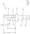
- FIG 2 shows a key which is particularly suitable for use in conjunction with the present invention.
- the key 14 comprises a first actuator portion 22 and a second actuator portion 24.
- the first actuator portion 22 has an opening 26 formed therein and the second actuator portion 24 has an opening 27 formed therein.
- the first and second actuator portions, 22 and 24, extend from a body 20 of the key.
- a tongue 28 Also extending from the body of the key is a tongue 28.
- the tongue 28 is provided with two holes 29 that enable the key 14 to be rigidly attached to a door such as that which is identified by reference numeral 10 in Figure 1.
- the first actuator portion 22 has an effective length L1 that is shorter than the effective length L2 of the second actuator portion 24.
- the difference in these lengths of the first and second actuator portions is identified as ⁇ L.
- the magnitude of ⁇ L can be used to distinguish one key from another even though they are made in a generally similar shape.
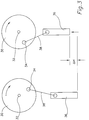
- Figure 3 is a highly schematic representation which is intended to illustrate the general operation of the present invention when the appropriate key is inserted into the support structure and a cam structure is rotated about a first axis.
- Figure 3 shows two representations of a mechanical structure in two sequential conditions.
- a rotatable member 30 is disposed for rotation about a first axis 32.
- a pin 34 is attached to the rotatable member 30.
- a plunger 36 is arranged to move in an upward and downward direction and the plunger 36 is attached to the pin 34 by a linkage arm 38.
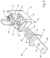
- Figure 4 is a perspective view showing a key 14 and a support structure 40. It should be understood that, for purposes of clarity, the upper portion of the support structure 40, or housing, is not shown in Figure 4.
- a cam structure is rotatably attached to the support structure 40 and comprises a first cam 42 and a second cam 44.
- the cam structure can be formed as a unitary element or, alternatively, the first and second cams can be rigidly attached together. Regardless of the exact means for providing the cam structure, the first and second cams should be arranged so that they rotate together about the first axis.
- the first cam 42 has a first lobe 46 while the second cam 44 has a second lobe 48.
- a first cam follower 43 is associated with the first cam 42 and its first lobe 46.
- a second cam follower 45 is associated with the second cam 44 and its second cam lobe 48.
- a spring mechanism 49 is associated with the cam structure to urge it to remain in a preferred position which will be described in greater detail below.
- a spring 50 is provided to urge the first and second cam followers in a generally downward direction toward their associated cams.
- a plunger 52 extends downward from the support structure 40 and is associated with the support structure so that it can move upward and downward in response to rotation of the cam structure.
- the cam structure will receive the key and permit the first and second cams to rotate against the resistence provided by the spring mechanism 49.
- the ends of the first and second actuator portions, 22 and 24, will prevent the first and second cam followers, 43 and 45, from locking the cams in a way that will prevent their further rotation.
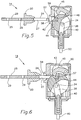
- Figure 5 is a sectioned side view of the structure shown in Figure 4. Since the second actuator portion 24 is longer than the first actuator portion 22 in Figure 4, the section view shows the structure of the second actuator portion 24 because it is the portion whose end will initially enter the support structure 40.
- the key 14 is shown in Figure 5 prior to entry through an opening 58 in the housing, or support structure 40.
- the view of Figure 5 also shows the second lobe 48 formed in the second cam 44. As the key 14 is inserted into the support structure 40, its end 57 can move into contact with the lobe 48 of the second cam 44. Upon initial contact of the end 57 of the second actuator portion 24, the first cam 44 will begin to rotate in a clockwise direction about its first axis which is its center of rotation.
- Figure 6 illustrates the arrangement of Figure 5 after the key 14 has been inserted into the support structure 44. Because of the contact of the end 57 and the lobe 48, the second cam 44 is urged in a clockwise direction about its central axis of rotation. In Figure 6, it can be seen that the end 57 of the second actuator portion 24 prevents the second cam follower 45 from dropping completely down into the second lobe 48. The second cam follower 45 is prevented from moving downward into the second lobe 48 even though spring 50 urges it in that preferred direction.
- both actuator portions of the key in combination with the size and shape of the first and second cams and their lobes, allow the key 14 to be inserted completely into the support structure 40 while the cam followers, 43 and 45, are prevented from dropping downward into their associated lobes.
- This cooperation of the components allows the key 14 to be inserted completely into the support structure 40 and also allows the plunger 52 to be raised so that the associated machinery can be actuated.
- Figure 7 shows the cam structure 70 rotated about its centerline without the presence of the key.
- the second cam follower 45 has dropped down into the second lobe 48 of the second cam 44. This results from the force provided by spring 50.
- the shape of the second cam follower 45 with its edge 59 that is also illustrated in Figure 5, further clockwise rotation of the cam structure 70 is prevented because of the interaction of the edge 59 with the portion 72 of the lobe 48. These shapes will interfere with each other and prevent further clockwise rotation of the cam structure 70.
- Figure 8 illustrates the cam structure 70 removed from the other components contained within the support structure 40.
- the first cam 42 is shown with its first lobe 46 and the second cam 44 is shown with its second lobe 48 and the portion 72 that interacts with the edge 59 of the cam follower described above in conjunction with Figure 7.
- the first axis 80 is the axis of rotation about which the cam structure rotates relative to the support structure 40.
- Pin 34 is shown in its position attached to the first cam 42. When assembled into the support structure 40, pin 34 is operatively associated with linkage arm 38 as described above.
- Figure 9 illustrates another view of the cam structure 70 that is shown in Figure 8.
- the first axis 80 is shown extending through an axial portion of the cam structure that is operatively associated with the spring mechanism 49 described above in conjunction with Figure 4.
- the primary advantages of the present invention are that movement of the plunger 52 can be inhibited unless the proper key 14 is used in association with a particular cam structure and, in addition, that two actuator portions of the key are required to rotate the cam structure about its first axis 80.
- both cam followers, 43 and 45 have to be retained in their position against the force of spring 50 while the first and second cams are moved in a clockwise direction. If either of the cam followers is permitted to drop down into its associated lobe, further movement is prevented.
- An additional advantage of the present invention is that the relative lengths of the first and second actuator portions, 22 and 24, can be altered to allow certain switches to be actuated only by certain matching keys.
- keys of many different combinations of actuator portion lengths can be provided in a factory where many different machines are used. Variation of the lengths of the first and second actuator portions can effectively provide many different key and switch combinations that individualize the safety mechanisms from machine to machine.
- the cam structure is manufactured so that the arcuate displacement of the first and second lobes matches the difference in length between the first and second actuator portions of the key. Therefore, the configuration of the key can provide many different possible combinations of lengths of the actuator portions and associated changes in the arcuate displacement of the first and second cams of the cam structure can be made to match these combinations. This provides the individualization described above.
Landscapes
- Engineering & Computer Science (AREA)
- Computer Security & Cryptography (AREA)
- Mechanisms For Operating Contacts (AREA)
- Push-Button Switches (AREA)
- Lock And Its Accessories (AREA)
Applications Claiming Priority (2)
| Application Number | Priority Date | Filing Date | Title |
|---|---|---|---|
| US394681 | 1995-02-24 | ||
| US08/394,681 US5473127A (en) | 1995-02-24 | 1995-02-24 | Interlock mechanism for a key operated door switch |
Publications (3)
| Publication Number | Publication Date |
|---|---|
| EP0729165A2 true EP0729165A2 (de) | 1996-08-28 |
| EP0729165A3 EP0729165A3 (de) | 1997-09-03 |
| EP0729165B1 EP0729165B1 (de) | 2001-08-22 |
Family
ID=23559983
Family Applications (1)
| Application Number | Title | Priority Date | Filing Date |
|---|---|---|---|
| EP96301278A Expired - Lifetime EP0729165B1 (de) | 1995-02-24 | 1996-02-26 | Verriegelungsmechanismus für mit einem Schlüssel betätigbarer Schalter |
Country Status (3)
| Country | Link |
|---|---|
| US (1) | US5473127A (de) |
| EP (1) | EP0729165B1 (de) |
| DE (1) | DE69614587T2 (de) |
Cited By (1)
| Publication number | Priority date | Publication date | Assignee | Title |
|---|---|---|---|---|
| WO2006086399A1 (en) * | 2005-02-11 | 2006-08-17 | Honeywell International Inc. | Elevator door interlock |
Families Citing this family (10)
| Publication number | Priority date | Publication date | Assignee | Title |
|---|---|---|---|---|
| DE4408024C5 (de) * | 1994-03-10 | 2007-09-06 | Euchner Gmbh + Co. Kg | Sicherheitsschalter |
| DE4436579C2 (de) * | 1994-10-13 | 1997-05-22 | Bernstein Hans Spezialfabrik | Sicherheitsschalter |
| EP0939415B1 (de) * | 1998-02-26 | 2005-12-14 | Idec Izumi Corporation | Sicherheitsschalter |
| US6013881A (en) * | 1999-03-30 | 2000-01-11 | Honeywell Inc. | Key operated safety interlock switch |
| DE502005002179D1 (de) * | 2004-08-07 | 2008-01-17 | Euchner Gmbh & Co Kg | Vorrichtung zum überwachen des zustandes einer schutzeinrichtung |
| FR2887071B1 (fr) * | 2005-06-14 | 2007-08-31 | Schneider Electric Ind Sas | Dispositif d'actionnement d'un appareil electrique interrupteur a moyens de blocage en rotation. |
| JP4710648B2 (ja) * | 2006-02-23 | 2011-06-29 | オムロン株式会社 | 安全スイッチ |
| DE502006007966D1 (de) * | 2006-07-03 | 2010-11-11 | Siemens Ag | positionsschalter |
| US8598477B2 (en) | 2009-10-13 | 2013-12-03 | Barton L. Garvin | Universal switch restraint device |
| US8937259B2 (en) | 2009-10-13 | 2015-01-20 | Barton L. Garvin | Universal electrical circuit breaker locking device |
Family Cites Families (10)
| Publication number | Priority date | Publication date | Assignee | Title |
|---|---|---|---|---|
| US3858018A (en) * | 1974-02-22 | 1974-12-31 | Gen Electric | Electrical switch with removable driving means |
| DE7627192U1 (de) * | 1976-08-31 | 1976-12-23 | Hans & Jos. Kronenberg Gmbh, 5060 Bensberg | Zwangskontakt-Schalteinrichtung, insbesondere für Aufzugstüren |
| DE3100862C2 (de) * | 1981-01-14 | 1984-02-09 | K.A. Schmersal Gmbh & Co, 5600 Wuppertal | Sicherheitsschalter |
| DE3112097C2 (de) * | 1981-03-27 | 1990-03-29 | Euchner & Co, 7022 Leinfelden-Echterdingen | "Sicherheitsschalter" |
| DE3330109C2 (de) * | 1983-08-20 | 1986-01-02 | K.A. Schmersal Gmbh & Co, 5600 Wuppertal | Elektrischer Schalter |
| US4658102A (en) * | 1984-09-08 | 1987-04-14 | K. A. Schmersal Gmbh & Co. | Electric switch |
| FR2579010B1 (fr) * | 1985-03-18 | 1987-04-10 | Telemecanique Electrique | Interrupteur electrique de securite |
| FR2613121B1 (fr) * | 1987-03-27 | 1993-12-10 | Telemecanique Electrique | Interrupteur a cle verrouillable par actionneur |
| FR2655182B1 (fr) * | 1989-11-27 | 1992-02-21 | Telemecanique | Systeme interrupteur de securite fonctionnant par insertion et extraction d'une cle. |
| DE4328296C1 (de) * | 1993-08-23 | 1994-11-24 | Euchner & Co | Sicherheitsschalter |
-
1995
- 1995-02-24 US US08/394,681 patent/US5473127A/en not_active Expired - Lifetime
-
1996
- 1996-02-26 DE DE69614587T patent/DE69614587T2/de not_active Expired - Fee Related
- 1996-02-26 EP EP96301278A patent/EP0729165B1/de not_active Expired - Lifetime
Cited By (2)
| Publication number | Priority date | Publication date | Assignee | Title |
|---|---|---|---|---|
| WO2006086399A1 (en) * | 2005-02-11 | 2006-08-17 | Honeywell International Inc. | Elevator door interlock |
| US7549516B2 (en) | 2005-02-11 | 2009-06-23 | Honeywell International Inc. | Elevator door interlock |
Also Published As
| Publication number | Publication date |
|---|---|
| EP0729165A3 (de) | 1997-09-03 |
| DE69614587T2 (de) | 2002-06-27 |
| US5473127A (en) | 1995-12-05 |
| DE69614587D1 (de) | 2001-09-27 |
| EP0729165B1 (de) | 2001-08-22 |
Similar Documents
| Publication | Publication Date | Title |
|---|---|---|
| US5473127A (en) | Interlock mechanism for a key operated door switch | |
| EP0450699B1 (de) | Abschliessvorrichtung mittels Vorhängeschloss von Handbedienteilen elektromechanischer Einrichtungen | |
| JP4659934B2 (ja) | 可逆的なプラグイン及び切断機構、並びにその鎖錠装置 | |
| KR101756565B1 (ko) | 개선된 회전식 차단 장치 | |
| EP0736218B1 (de) | Sicherheitsschalter | |
| US5845523A (en) | Electronic input and dial entry lock | |
| EP0553885B1 (de) | Sicherheitsschalter | |
| EP1863733B1 (de) | Sicherheitsschloss für aufzugsschachttür, das das eindringen in den schacht durch die schachttür erfasst, und so ausgestatteter aufzug | |
| US5622253A (en) | Safety switch | |
| WO1998023830A1 (en) | Catch mechanism for locks | |
| US4186578A (en) | Tamper preventing lock | |
| AU2001291918A1 (en) | Electromechanical cylinder lock-key-combination | |
| EP1322828A1 (de) | Elektromechanisches zylinderschloss und schlüssel | |
| US4598182A (en) | Lock inhibitor for toggle switch actuator | |
| JP5122559B2 (ja) | エネルギを配給するためのスイッチギヤ組立体のための開閉装置 | |
| US4114001A (en) | Electrical switch having interlock between door and switch | |
| KR20000048231A (ko) | 로크를 사용한 스위치의 수동 작동 인터로크 장치 | |
| US3566632A (en) | Steering column and transmission control lock | |
| GB2297354A (en) | An electronic combination lock having a dial-shaped handle with a keypad | |
| US4986580A (en) | Lock with a mechanism for locking and unlocking by means of an electromagnet | |
| EP2506280B1 (de) | Manipulationssicheres Sicherheitsschaltersystem mit Schutzsperre | |
| JPH0676675A (ja) | 安全用スイッチ装置 | |
| KR20080070685A (ko) | 안전 스위치 | |
| US3806675A (en) | Key indicating switch | |
| JP3577731B2 (ja) | キースイッチ |
Legal Events
| Date | Code | Title | Description |
|---|---|---|---|
| PUAI | Public reference made under article 153(3) epc to a published international application that has entered the european phase |
Free format text: ORIGINAL CODE: 0009012 |
|
| AK | Designated contracting states |
Kind code of ref document: A2 Designated state(s): DE GB |
|
| PUAL | Search report despatched |
Free format text: ORIGINAL CODE: 0009013 |
|
| AK | Designated contracting states |
Kind code of ref document: A3 Designated state(s): DE GB |
|
| 17P | Request for examination filed |
Effective date: 19980214 |
|
| 17Q | First examination report despatched |
Effective date: 19991006 |
|
| GRAG | Despatch of communication of intention to grant |
Free format text: ORIGINAL CODE: EPIDOS AGRA |
|
| GRAG | Despatch of communication of intention to grant |
Free format text: ORIGINAL CODE: EPIDOS AGRA |
|
| GRAH | Despatch of communication of intention to grant a patent |
Free format text: ORIGINAL CODE: EPIDOS IGRA |
|
| GRAH | Despatch of communication of intention to grant a patent |
Free format text: ORIGINAL CODE: EPIDOS IGRA |
|
| GRAA | (expected) grant |
Free format text: ORIGINAL CODE: 0009210 |
|
| AK | Designated contracting states |
Kind code of ref document: B1 Designated state(s): DE GB |
|
| REF | Corresponds to: |
Ref document number: 69614587 Country of ref document: DE Date of ref document: 20010927 |
|
| REG | Reference to a national code |
Ref country code: GB Ref legal event code: IF02 |
|
| PLBE | No opposition filed within time limit |
Free format text: ORIGINAL CODE: 0009261 |
|
| STAA | Information on the status of an ep patent application or granted ep patent |
Free format text: STATUS: NO OPPOSITION FILED WITHIN TIME LIMIT |
|
| 26N | No opposition filed | ||
| PGFP | Annual fee paid to national office [announced via postgrant information from national office to epo] |
Ref country code: GB Payment date: 20080108 Year of fee payment: 13 Ref country code: DE Payment date: 20080229 Year of fee payment: 13 |
|
| GBPC | Gb: european patent ceased through non-payment of renewal fee |
Effective date: 20090226 |
|
| PG25 | Lapsed in a contracting state [announced via postgrant information from national office to epo] |
Ref country code: DE Free format text: LAPSE BECAUSE OF NON-PAYMENT OF DUE FEES Effective date: 20090901 |
|
| PG25 | Lapsed in a contracting state [announced via postgrant information from national office to epo] |
Ref country code: GB Free format text: LAPSE BECAUSE OF NON-PAYMENT OF DUE FEES Effective date: 20090226 |