EP0727414B1 - Verfahren mit hoher Ausbeute zur Herstellung von Harnstoff - Google Patents
Verfahren mit hoher Ausbeute zur Herstellung von Harnstoff Download PDFInfo
- Publication number
- EP0727414B1 EP0727414B1 EP96101058A EP96101058A EP0727414B1 EP 0727414 B1 EP0727414 B1 EP 0727414B1 EP 96101058 A EP96101058 A EP 96101058A EP 96101058 A EP96101058 A EP 96101058A EP 0727414 B1 EP0727414 B1 EP 0727414B1
- Authority
- EP
- European Patent Office
- Prior art keywords
- reactor
- urea
- ammonia
- process according
- liquid mixture
- Prior art date
- Legal status (The legal status is an assumption and is not a legal conclusion. Google has not performed a legal analysis and makes no representation as to the accuracy of the status listed.)
- Expired - Lifetime
Links
- XSQUKJJJFZCRTK-UHFFFAOYSA-N Urea Chemical compound NC(N)=O XSQUKJJJFZCRTK-UHFFFAOYSA-N 0.000 title claims abstract description 83
- 239000004202 carbamide Substances 0.000 title claims abstract description 81
- 238000000034 method Methods 0.000 title claims abstract description 67
- 230000015572 biosynthetic process Effects 0.000 title claims abstract description 27
- 238000003786 synthesis reaction Methods 0.000 title claims abstract description 26
- QGZKDVFQNNGYKY-UHFFFAOYSA-N Ammonia Chemical compound N QGZKDVFQNNGYKY-UHFFFAOYSA-N 0.000 claims abstract description 156
- CURLTUGMZLYLDI-UHFFFAOYSA-N Carbon dioxide Chemical compound O=C=O CURLTUGMZLYLDI-UHFFFAOYSA-N 0.000 claims abstract description 117
- 229910002092 carbon dioxide Inorganic materials 0.000 claims abstract description 81
- 229910021529 ammonia Inorganic materials 0.000 claims abstract description 63
- KXDHJXZQYSOELW-UHFFFAOYSA-N carbonic acid monoamide Natural products NC(O)=O KXDHJXZQYSOELW-UHFFFAOYSA-N 0.000 claims abstract description 41
- BVCZEBOGSOYJJT-UHFFFAOYSA-N ammonium carbamate Chemical compound [NH4+].NC([O-])=O BVCZEBOGSOYJJT-UHFFFAOYSA-N 0.000 claims abstract description 37
- 239000001569 carbon dioxide Substances 0.000 claims abstract description 36
- 238000006243 chemical reaction Methods 0.000 claims abstract description 34
- 238000000746 purification Methods 0.000 claims abstract description 20
- 239000007864 aqueous solution Substances 0.000 claims abstract description 8
- 239000000243 solution Substances 0.000 claims abstract description 8
- 239000007788 liquid Substances 0.000 claims description 51
- 239000000203 mixture Substances 0.000 claims description 50
- 229910001868 water Inorganic materials 0.000 claims description 47
- XLYOFNOQVPJJNP-UHFFFAOYSA-N water Substances O XLYOFNOQVPJJNP-UHFFFAOYSA-N 0.000 claims description 34
- 229910000069 nitrogen hydride Inorganic materials 0.000 claims description 32
- 238000000926 separation method Methods 0.000 claims description 18
- 238000009833 condensation Methods 0.000 claims description 15
- 230000005494 condensation Effects 0.000 claims description 14
- 238000000354 decomposition reaction Methods 0.000 claims description 7
- 239000012530 fluid Substances 0.000 claims description 7
- 238000004519 manufacturing process Methods 0.000 claims description 7
- 238000010438 heat treatment Methods 0.000 claims description 2
- 238000011084 recovery Methods 0.000 abstract description 3
- 239000007789 gas Substances 0.000 description 21
- KXDHJXZQYSOELW-UHFFFAOYSA-M Carbamate Chemical compound NC([O-])=O KXDHJXZQYSOELW-UHFFFAOYSA-M 0.000 description 15
- 239000012071 phase Substances 0.000 description 6
- 238000005516 engineering process Methods 0.000 description 5
- 239000000047 product Substances 0.000 description 5
- 230000018044 dehydration Effects 0.000 description 4
- 238000006297 dehydration reaction Methods 0.000 description 4
- 239000000126 substance Substances 0.000 description 4
- 239000001099 ammonium carbonate Substances 0.000 description 3
- 230000002349 favourable effect Effects 0.000 description 3
- 239000000376 reactant Substances 0.000 description 3
- ATRRKUHOCOJYRX-UHFFFAOYSA-N Ammonium bicarbonate Chemical compound [NH4+].OC([O-])=O ATRRKUHOCOJYRX-UHFFFAOYSA-N 0.000 description 2
- BVKZGUZCCUSVTD-UHFFFAOYSA-M Bicarbonate Chemical compound OC([O-])=O BVKZGUZCCUSVTD-UHFFFAOYSA-M 0.000 description 2
- 235000012501 ammonium carbonate Nutrition 0.000 description 2
- 230000003247 decreasing effect Effects 0.000 description 2
- 230000000694 effects Effects 0.000 description 2
- 239000007791 liquid phase Substances 0.000 description 2
- 239000011541 reaction mixture Substances 0.000 description 2
- 239000002699 waste material Substances 0.000 description 2
- BVKZGUZCCUSVTD-UHFFFAOYSA-L Carbonate Chemical compound [O-]C([O-])=O BVKZGUZCCUSVTD-UHFFFAOYSA-L 0.000 description 1
- 235000012538 ammonium bicarbonate Nutrition 0.000 description 1
- 150000003863 ammonium salts Chemical class 0.000 description 1
- 230000000903 blocking effect Effects 0.000 description 1
- 229910052799 carbon Inorganic materials 0.000 description 1
- 239000007795 chemical reaction product Substances 0.000 description 1
- 238000001704 evaporation Methods 0.000 description 1
- 230000008020 evaporation Effects 0.000 description 1
- 239000011552 falling film Substances 0.000 description 1
- 239000010408 film Substances 0.000 description 1
- VUZPPFZMUPKLLV-UHFFFAOYSA-N methane;hydrate Chemical compound C.O VUZPPFZMUPKLLV-UHFFFAOYSA-N 0.000 description 1
- 230000004048 modification Effects 0.000 description 1
- 238000012986 modification Methods 0.000 description 1
- 230000001376 precipitating effect Effects 0.000 description 1
- 238000002360 preparation method Methods 0.000 description 1
- 150000003839 salts Chemical class 0.000 description 1
- 239000007787 solid Substances 0.000 description 1
- 239000002904 solvent Substances 0.000 description 1
- 239000003643 water by type Substances 0.000 description 1
Images

Classifications
-
- C—CHEMISTRY; METALLURGY
- C07—ORGANIC CHEMISTRY
- C07C—ACYCLIC OR CARBOCYCLIC COMPOUNDS
- C07C273/00—Preparation of urea or its derivatives, i.e. compounds containing any of the groups, the nitrogen atoms not being part of nitro or nitroso groups
- C07C273/02—Preparation of urea or its derivatives, i.e. compounds containing any of the groups, the nitrogen atoms not being part of nitro or nitroso groups of urea, its salts, complexes or addition compounds
- C07C273/04—Preparation of urea or its derivatives, i.e. compounds containing any of the groups, the nitrogen atoms not being part of nitro or nitroso groups of urea, its salts, complexes or addition compounds from carbon dioxide and ammonia
-
- Y—GENERAL TAGGING OF NEW TECHNOLOGICAL DEVELOPMENTS; GENERAL TAGGING OF CROSS-SECTIONAL TECHNOLOGIES SPANNING OVER SEVERAL SECTIONS OF THE IPC; TECHNICAL SUBJECTS COVERED BY FORMER USPC CROSS-REFERENCE ART COLLECTIONS [XRACs] AND DIGESTS
- Y02—TECHNOLOGIES OR APPLICATIONS FOR MITIGATION OR ADAPTATION AGAINST CLIMATE CHANGE
- Y02P—CLIMATE CHANGE MITIGATION TECHNOLOGIES IN THE PRODUCTION OR PROCESSING OF GOODS
- Y02P20/00—Technologies relating to chemical industry
- Y02P20/50—Improvements relating to the production of bulk chemicals
- Y02P20/582—Recycling of unreacted starting or intermediate materials
Definitions
- the present invention relates to a process for high yield synthesis of urea.
- the present invention relates to an improved-yield process for urea synthesis, comprising the reaction of ammonia and carbon dioxide under high temperature and pressure conditions, the following separation of urea from the mixture containing the unreacted products, and the recycle of the latter to the reactor.
- reaction steps are not normally carried out in separate zones of the reactor, but they occur simultaneously inside the reaction mixture, which, therefore, comprises urea, water, ammonia, carbon dioxide and ammonium carbamate, with relative concentrations in the different reactor areas, which depend on the several thermodynamic and kinetic factors which contribute to the process.
- the industrial processes for urea production normally perform the synthesis inside a reactor to which NH 3 , CO 2 and the aqueous solutions of ammonium carbonate and/or carbamate from the unconverted reactants recycle streams are fed, at temperatures comprised within the range of from 170 to 200°C, under pressures of at least 130 atm, with a molar ratio of NH 3 :CO 2 comprised within the range of from 2.5 to 4.5, as based on total feed streams.
- the molar ratio of H 2 O:CO 2 fed to the reactor is generally comprised within the range of from 0.5 to 0.6. Under such conditions, the product discharged from the reactor shows conversion rates comprised within the range of from 50 to 65%, based on fed CO 2 .
- the effluent stream from the reactor additionally contains large amounts of CO 2 , prevailingly as unconverted ammonium carbamate.
- the separation of urea from these products is carried out in a plurality of sections operating at high temperature and under decreasing pressures, inside which both the decomposition of ammonium carbamate into NH 3 and CO 2 (products made available for being recycled to the reactor), and the evaporation of reaction water take place, with high-purity urea being finally obtained which is sent to the subsequent prilling step.
- the carbamate separation and recycle section requires investment costs for the facilities which considerably add to the cost of the end product.
- the present Applicant found now a process which makes it possible the difficulties and limitations affecting the traditional industrial processes, as mentioned above, to be overcome, with CO 2 conversions into urea of higher than 70% being reached.
- the object of the present invention is an improved process for urea synthesis from ammonia and carbon dioxide, with ammonium carbamate being formed as an intermediate species, which comprises the following steps:
- fresh ammonia and fresh carbon dioxide are continuously fed to the facility in order to compensate for (i.e., replenish) the corresponding amounts of reactants converted into urea and discharged from the end separation and prilling sections.
- Fresh ammonia and fresh carbon dioxide can be directly fed to the reactor, but they are preferably at least partially used as the drive fluid for one or more ejector(s), in order to supply the necessary drive for said first gas stream discharged from the (c) stripping step, and/or ammonium carbamate coming from (d) condensation step to circulate.
- Ammonia is particularly preferred for use for that purpose.
- fresh ammonia or fresh carbon dioxide can be used either totally or partially, as the stripping fluid in the stripper and/or can be directly sent to the condenser.
- the synthesis reactor normally operates at temperatures comprised within the range of from 160 to 215°C, preferably comprised within the range of from 170 to 205°C, and under pressures comprised within the range of from 9.1 to 25.3 MPa (90 to 250 abs.atm), preferably of from 12.1 to 18.2 MPa (120 to 180 abs.atm), with molar ratios of ammonia:carbon dioxide preferably comprised within the range of from 2.1 to 6.0, more preferably of from 2.5 to 4.5.
- the reactor is normally equipped with a plurality of trays, of a type selected from the different types known in the art, so as to realize the optimal conditions of plug flow, possibly also in the presence of two-phase systems.
- the reactor can also comprise a plurality of reaction zones, suitably interconnected with each other, possibly with different feed streams.
- Heat developed and, more generally, the temperature level of the reactor in the (a) step is controlled by acting on the temperature level of carbon dioxide and/or ammonia stream(s) fed to the reactor and/or based on the subdivision of said feed streams between stripper, condenser and reactor and/or on the amount of heat removed in the condenser.
- the reactor must display a value of liquid hold-up which will enable the residence time of said liquid inside the reactor to be comprised within the range of from a few minutes up to some ten minutes, in order to allow ammonium carbamate formed by the reaction of ammonia with carbon dioxide in the (d) condensation step and/or inside the same reactor, to undergo dehydration into urea.
- a second gas stream can be separated, as an effluent stream from reactor top, which is rich in inert species which must be removed.
- a gas stream is preferably submitted to condensation in order to recover ammonia and carbon dioxide contained in it, which are then directly recycled to the reactor.
- such a gas stream is sent to the decomposition-stripping step, and the inert species are then subsequently separated from recycled carbamate stream to reactor.
- the reactor leaving stream and, generally, most liquid streams which are formed in the process usually contain ammonia in excess.
- liquid is indifferently used with reference to streams or mixtures of the process according to the present invention, which are constituted either by one single liquid phase, or by a mixed liquid-vapour phase.
- gas is used for those streams or mixtures in which the liquid phase is substantially absent.
- the (c) decomposition-stripping step is normally carried out in a stripper usually heated by indirect, high pressure steam.
- the temperature of the stripper is normally comprised within the range of from 160 to 220°C, and the pressure inside it is equal to, or slightly lower than, the pressure inside the reactor, so as to make possible the decomposition products (first gas stream) to be recycled using, as driving means, only, and possibly, ejectors.
- ammonium carbamate tends to rapidly decompose forming ammonia and carbon dioxide, and urea already formed inside the reactor remains substantially unchanged.
- the stripping can be carried out by using fresh ammonia or fresh carbon dioxide as the drive gases.
- U.S. patent No. 3,356,723 to STAMICARBON discloses the use of carbon dioxide as stripping gas.
- G.B. patent No. 1,016,220 to SNAMPROGETTI discloses the use of ammonia in order to achieve the same purpose.
- the decomposition-stripping step is carried out by using, as the drive gas, the same ammonia excess present in the reactor leaving stream. Further details on such a preferred technology can be found, e.g., in U.S. patent 3,876,696 to SNAMPROGETTI, the contents of which are incorporated hereto by reference. This last technology is referred to as "self-stripping".
- the decomposition-stripping step can also be carried out inside two equipment pieces (strippers) in cascade, possibly of different types from each other and operating under different conditions from each other, as disclosed, e.g., in G.B. patent 1,581,505, the contents of which are incorporated hereto by reference.
- a first gas mixture of ammonia and carbon dioxide having a very low water content is obtained.
- the water content is normally comprised within the range of from 0.0 to 10%, preferably of from 0.0 to 5.0% by weight, based on total gas mixture weight.
- Such a small water content is that content which is normally obtained from the high-pressure stripping steps carried out according to the processes cited above.
- the (c) decomposition-stripping step is carried out inside tube-bundle apparatuses with falling liquid film.
- the effluent mixture from the reactor, together with the fourth liquid mixture coming from the steps downstream from the stripper, is preferably fed to the head of the apparatus and forms a falling film along the walls of the tube bundle.
- apparatuses can be used in the present process, which are suitable for the intended purpose.
- the (d) condensation step is normally carried out inside suitable condensers, e.g., of tube-bundle or surface types, in which the condensation heat is used in order to heat other fluid streams.
- the condensation heat is preferably used to generate steam, but it can also be used to supply heat to one of the subsequent medium or low pressure ammonium carbamate decomposition steps.
- the condensation step can be carried out under the usual conditions (temperature, pressure and composition) used in the processes known from the prior art, provided that these are such as to prevent solid ammonium carbamate from forming in the condenser and/or in the outlet lines from it.
- the separation of urea from ammonia and ammonium carbamate still present in the second liquid effluent stream from the decomposition-stripping step is carried out, according to the (e) step of the present process, in subsequent decomposition and separation sections, operating under medium (from 15 to 25 abs.atm) and/or low (from 3 to 8 abs.atm) pressure conditions.
- such (e) separation step can be carried out by means of any of the methods described in the specific sector literature, which make it possible a liquid recycle stream to be obtained which contains an aqueous solution of ammonium carbamate and, possibly, also a stream which is essentially constituted by ammonia.
- Suitable separation-purification sections for the purposes of the present invention are, e.g., those which are schematically represented in Figures 1-5 of "Encyclopedia of Chemical Technology" ibid .
- Urea so separated from ammonium carbamate and ammonia is generally obtained as an aqueous solution which is then submitted to an end step of vacuum dehydration (down to 0.1 abs.atm) with on the one side water, and on the other side, substantially pure urea being obtained which is then sent to normal prilling processes, and so forth.
- the (e) urea separation-purification step also includes the end dehydration step and the section of purification of waste effluent waters from synthesis facility.
- the several, either liquid or two-phase streams containing ammonium carbamate, coming from the several sub-sections of the (e) step are gathered one single recycle stream which constitutes said fourth liquid mixture which is then either totally or partially sent to the first decomposition-stripping step.
- recycle ammonia and carbon dioxide can be present as ammonium carbonate, hydrogencarbonate or carbamate, or a mixture thereof, according to mixture temperature and pressure conditions.
- the process according to the present invention makes it possible the water amount fed to the reactor to be meaningfully decreased, down to such a level as to have, at reactor inlet, a molar ratio of H 2 O:CO 2 which is always lower than 0.3 (in which CO 2 inside the reactor is conventionally considered as being in carbamate form, as specified hereinabove). In such a way, a considerable general decrease is obtained also in water amount present in the reaction zone.
- This makes it possible urea synthesis to be carried out with particularly high conversion values, preferably comprised within the range of from 70 to 75% per each cycle, with no need for resorting to particularly complex and burdensome technical solutions in order to accomplish that result.
- the present process furthermore displays the advantage of being suitable for being easily and surprisingly carried out by supplying a small number of simple modifications to an already existing traditional facility, provided it is equipped with a high-pressure stripping step.
- it will be enough to modify the facility in such a way as to send to said stripping step, either totally, or partially, the recycled carbamate containing stream coming from the steps downstream from the same stripper.
- a further object of the present invention is a method for improving the yield of an existing process for urea production, which operates with a high-pressure synthesis section comprising at least one reaction step from which a urea solution is transferred to a (self) stripping step, and subsequent urea purification and concentration steps, from which an aqueous ammonium carbamate solution is obtained, wherein in from 50 to 100% of said aqueous solution is combined with said urea solution and fed to said (self)stripping step.
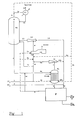
- the reactor R1 In the Flow Scheme reported in Figure 1, the reactor R1 can be seen which, through the overflow T and the line 4, is connected with the stripper S1. The latter is connected, at its bottom, with the urea separation-purification section P from which, through line 5, carbamate (line 5a) is recycled to line 4 and, possibly, (lines 5b and 5c) to the condenser C2. With the condenser C2, the stripper S1 top is connected through line 7, ejector E1, and lines 7a and 7b.
- the condenser outlet is represented by line 8 which is then connected with the reactor R1 through the ejector E2, to which also the line 10 comes, which conveys free ammonia (line 2) and recycled ammonia (line 9) from urea separation and purification section P.
- the line 1 for fresh carbon dioxide can be indifferently connected either with the reactor (line 1a) or with the condenser (line 1b) or with the stripper bottom (line 1c), or, also, with a plurality of such equipment pieces.
- the line 3 from the top of reactor R1 is connected with the condenser C1 (line 3a) and/or with the stripper S1 (line 3b) or the condenser C2 (line 3c).
- Fresh ammonia, compressed and fed through line 2, is combined with recovered ammonia (line 9), coming from section P, and the resulting stream is partially sent to reactor R1 through line 10 and ejector E2, and partially to carbamate condenser C2 through ejector E1 (line 10b).
- ammonia can be either totally or partially fed to stripper S1 through line 10a; in this case, line 10b (and, consequently, ejector E1) can be absent. This is the case when stripping is carried out with ammonia.
- from 30 to 90% of ammonia from lines 2 and 9 is fed to the ejector E1, via 10b, with the residual portion thereof being sent to the ejector E2, via line 10.
- said streams 10, 10a and 10b prevailingly contain ammonia in liquid state.
- Fresh CO 2 (line 1) can be analogously sent through lines 1a and/or 1b, according to the enthalpy requirements of reactor R1, but can also be sent, through line 1c, to stripper S1, in which case it will be also used as stripping medium.
- fresh carbon dioxide after being compressed, is mostly directly sent to the reactor (more than 50% thereof), and partially sent to condenser C2.
- the total reactor feed is constituted by streams 1a and 11, the latter with a very limited water content, partly deriving from the possible urea formation already in the ammonium carbamate condenser C2.
- the reactor preferably operates with an overall feed in which the molar ratio of water to CO 2 is lower than 0.2.
- the stream 5a contains from 70 to 100% of the recovered stream 5.
- the possibly residual portion of that recovery stream is sent to the condenser C2, either directly through line 5c, or indirectly through 5b.
- the feed 4a to stripper S1 is subdivided into partial feed streams fed to said stripper at different levels thereof.
- the gas phase present in reactor overhead is sent, through lines 3 and 3a, to the condenser C1 in which the inert species present in fresh NH 3 and CO 2 feed streams are separated; according to an alternative route, a portion of said gas phase can be sent, by means of the line 3b, to stripper S1, to act as the stripping medium, or it can be directly sent to the condenser C2 (line 3c).
- it is condensed, under a pressure which is either equal to, or slightly lower than, the pressure existing inside the reactor, and at an as high as possible temperature, preferably higher than 150°C, in order to obtain a liquid stream (the third liquid mixture) prevailingly containing ammonium carbamate and ammonia and minor water amounts and, possibly, urea amounts.
- the latter is formed during the condensation step, with the operating conditions being already favourable to partially shift the preceding reported chemical equilibrium (1b) to the right.
- the so obtained liquid stream si fed to the reactor through line 8 and ejector E2.
- the stream 6 discharged from the bottom of stripper S1, containing all produced urea, is sent to the subsequent purification and concentration steps, which are schematically combined in P section, in the Flow Scheme of Figure 1. From here the recovered NH 3 and carbamate streams, already cited above, are derived, and pure urea and water are discharged through lines 15 and, respectively, 14.
- compositions of the several streams are reported by referring to the basic components urea, ammonia, carbon dioxide and water, independently on carbon dioxide, in those liquid streams which contain ammonia, substantially being in ammonium carbamate form.
- a process for urea synthesis is operated by feeding to the stripper the recovery stream coming from urea separation/purification section (synthesis loop according to the present invention). Reference is made to the Flow Scheme reported in Figure 1.
- fresch streams of 45,461 Kg/h and 8,573 kg/h of CO 2 and 41,753 kg/h of NH 3 , containing a total amount of 636 kg/h of inerts, are fed to reactor R1.
- the reactor operates under 15.9 MPa (157 abs.atm) and 188°C
- the condenser C2 operates under 15.4 MPa (152 abs.atm) and at approximately 155°C.
- the reactor overhead gas stream 3 is totally sent to condenser C1, allowed to operate at 75°C; from this, a stream is discharged which contains the amount of 636 kg/h of inerts originally contained in the feed to the reactor, besides negligible amounts of NH 3 and CO 2 , not taken into consideration in the above balance.
- the stream 4 is sent to the stripper S1, through line 4a, after being combined with stream 5a; the stripper operates under 148 abs.atm, with a bottom temperature of 205°C, with no feed of stripping gas (self-stripper).
- These are substantially constituted, in this particular case, by the typical medium- and low-pressure separation sections, and by the concentration section which characterize the traditional SNAMPROGETTI urea process the general scheme of which is reported, e.g., on page 561 of "Encyclopedia of Chemical Technology", ibid .
- the process for urea synthesis exemplified above is characterized by a conversion of CO 2 into urea, i.e. by a molar ratio of (produced urea):(total CO 2 fed) of 0.73.
- a process for urea synthesis operates with the recovered stream from urea separation/purification section (traditional synthesis loop) being fed to the high-pressure condenser. Reference is made to the Flow Scheme reported in Figure 2.
- the reactor R1, the condenser C2 and the stripper S1 (self-stripper) operate under temperature and pressure conditions which are exactly the same as of the preceding Example 1.
- the reactor R1 is fed with:
- This stream is sent to the stripper S1 through the line 4.
- the gas stream 7 discharged from the head of the stripper is directly sent to the condenser C2.
- the liquid stream 6 discharged from stripper bottom and containing all produced urea, is sent to the subsequent purification/concentration section P, which also allows excess NH 3 and carbamate, still present in the same stream, to be recycled through lines 5 and 9.
- the traditional synthesis loop taken into consideration in this comparison example is characterized by a conversion of CO 2 into urea, i.e., by a molar ratio of (produced urea):(total fed CO 2 ) of 0.62.
Landscapes
- Chemical & Material Sciences (AREA)
- Organic Chemistry (AREA)
- Organic Low-Molecular-Weight Compounds And Preparation Thereof (AREA)
Claims (19)
- Verfahren zur Harnstoffsynthese aus Ammoniak und Kohlendioxid unter Bildung von Ammoniumcarbamat als Zwischenprodukt, bei dem:wobei ein Anteil von 50 bis 100% des in Stufe (e) gebildeten vierten flüssigen Gemisches der ersten Zersetzungs-Stripp-Stufe (S1) zugeführt wird und der Restanteil, sofern vorhanden, dem Reaktor (R1) oder vorzugsweise der Kondensationsstufe (C2) zugeführt wird,(a) Ammoniak und Kohlendioxid in mindestens einen Reaktor (R1) eingeführt und miteinander reagieren gelassen werden, wobei das Molverhältnis NH3:CO2 entweder als solches oder als Ammoniumcarbamat im Bereich von 2,1 bis 10 liegt und ein erstes, Harnstoff, Ammoniumcarbamat, Wasser und Ammoniak enthaltendes flüssiges Gemisch gebildet wird,(b) das erste flüssige Gemisch in eine Zersetzungs-Stripp-Stufe (S1) überführt wird,(c) das erste flüssige Gemisch in der Zersetzungs-Stripp-Stufe (S1) erhitzt wird, wobei im wesentlichen unter dem gleichen Druck gearbeitet wird, wie er in dem Reaktor vorherrscht, so daß ein Teil des Ammoniumcarbamats zu Ammoniak und Kohlendioxid zersetzt wird, und gleichzeitig das flüssige Gemisch mit einem ersten, Ammoniak und Kohlendioxid enthaltenden Gasgemisch gestrippt wird, wodurch ein Harnstoff, Wasser, Ammoniak und den nicht zersetzten Anteil des Ammoniumcarbamats enthaltendes zweites flüssiges Gemisch gebildet wird,(d) das erste Gasgemisch, gegebenenfalls durch einen Ejektor (E1), in eine Kondensationsstufe (C2) überführt wird, in der im wesentlichen unter dem gleichen Reaktordruck gearbeitet und das Gemisch kondensiert wird, wodurch ein Ammoniumcarbamat und Ammoniak enthaltendes drittes flüssiges Gemisch gebildet wird, das, gegebenenfalls durch einen Ejektor (E2), in den Reaktor der Stufe (a) zurückgeführt wird,(e) der in dem zweiten flüssigen Gemisch enthaltene Harnstoff in einer oder mehreren sich anschließenden Zersetzungs/Abtrennstufen (P) unter Erhalt von praktisch reinem Harnstoff gewonnen wird, wobei ein Wasser, Ammoniak und Ammoniumcarbamat enthaltendes viertes flüssiges Gemisch und gegebenenfalls ein im wesentlichen Ammoniak enthaltender fünfter Strom gebildet wird,
dadurch gekennzeichnet, daß der Anteil des vierten flüssigen Gemisches mit dem ersten flüssigen Gemisch kombiniert wird. - Verfahren nach Anspruch 1, wobei das Verhältnis NH3:CO2 im Inneren des Reaktors im Bereich von 2,5 bis 4,5 liegt.
- Verfahren nach Anspruch 1 oder 2, wobei der Reaktor mit Böden versehen ist und unter Pfropfenströmungsbedingungen betrieben wird.
- Verfahren nach irgendeinem der vorangehenden Ansprüche, wobei der Reaktor eine Vielzahl von Reaktionszonen aufweist, die auf geeignete Weise miteinander verbunden sind und gegebenenfalls unterschiedliche Einsatzmaterialströme aufweisen.
- Verfahren nach irgendeinem der vorangehenden Ansprüche, wobei das Antriebsfluid des in Stufe (d) gegebenenfalls vorgesehen Ejektors zur Zurückführung des dritten flüssigen Gemisches zumindest zum Teil aus Einsatz-Ammoniak besteht.
- Verfahren nach irgendeinem der vorangehenden Ansprüche 1 bis 4, wobei Ammoniak zumindest teilweise direkt der Zersetzungs-Stripp-Stufe zugeführt wird.
- Verfahren nach irgendeinem der vorangehenden Ansprüche 1 bis 4, wobei zumindest ein Teil des Einsatz-Ammoniaks als Antriebsfluid in einem zur Zirkulierung des ersten Gasgemisches verwendeten Ejektor verwendet wird.
- Verfahren nach irgendeinem der vorangehenden Ansprüche 1 bis 4, wobei die Zersetzungs-Stripp-Stufe unter Selbst-Stripp-Bedingungen betrieben wird.
- Verfahren nach irgendeinem der vorangehenden Ansprüche 1 bis 4, wobei frisches Kohlendioxid zumindest teilweise direkt der Zersetzungs-Stripp-Stufe zugeführt wird.
- Verfahren nach irgendeinem der vorangehenden Ansprüche 1 bis 4, wobei Kohlendioxid zumindest teilweise der Kondensationsstufe (d) zugeführt wird.
- Verfahren nach irgendeinem der vorangehenden Ansprüche, wobei der Reaktor in Stufe (a) bei Temperaturen im Bereich von 170 bis 205°C und unter Drücken im Bereich von 12 bis 18 MPa (120 bis 180 abs. atm) arbeitet.
- Verfahren nach irgendeinem der vorangehenden Ansprüche, wobei die Zersetzungs-Stripp-Stufe (c) in einem Stripper durchgeführt wird, der bei einer Temperatur im Bereich von 160 bis 220°C arbeitet und indirekt mit Hochdruckdampf beheizt wird.
- Verfahren nach irgendeinem der vorangehenden Ansprüche, wobei die Zersetzungs-Stripp-Stufe (c) in einer Vorrichtung mit zwei Teilen, die kaskadenförmig angeordnet sind und sich gegebenenfalls hinsichtlich des Typs voneinander unterscheiden und unter unterschiedlichen Bedingungen arbeiten, durchgeführt wird.
- Verfahren nach irgendeinem der vorangehenden Ansprüche, wobei das durchschnittliche Molverhältnis H2O:CO2 in dem Einsatzmaterial für den Reaktor in Stufe (a) kleiner als 0,3, vorzugsweise kleiner als 0,2 ist.
- Verfahren nach irgendeinem der vorangehenden Ansprüche, wobei zumindest ein Teil der Umwandlung von Kohlendioxid in Harnstoff während der Kondensationsstufe (d) stattfindet.
- Verfahren nach irgendeinem der vorangehenden Ansprüche, wobei 70 bis 100% des in Stufe (e) gebildeten vierten flüssigen Gemisches mit dem ersten flüssigen Gemisch kombiniert und das sich ergebende kombinierte Gemisch der ersten Zersetzungs-Stripp-Stufe (c) zugeführt wird.
- Verfahren nach irgendeinem der vorangehenden Ansprüche, wobei das Einsatzmaterial für die Zersetzungs-Stripp-Stufe aufgeteilt und die sich ergebenden Teilströme unterschiedlichen Stripperniveaus zugeführt werden.
- Verfahren zur Verbesserung der Ausbeute eines existierenden Verfahrens zur Harnstoff-Herstellung, das mit einem Hochdrucksyntheseabschnitt arbeitet, der einen ReaktionsStufe umfaßt, aus dem eine Harnstoff-haltige Lösung einer (Selbst)Stripp-Stufe und anschließenden Harnstoff-Reinigungs- und Konzentrations-Stufen zugeführt wird, aus denen eine wäßrige Lösung von Ammoniumcarbamat erhalten wird, wobei ein Anteil von 50 bis 100% davon der (Selbst)Stripp-Stufe zugeführt wird, dadurch gekennzeichnet, daß der Anteil der wäßrigen Lösung mit der Harnstoff-haltigen Lösung kombiniert wird.
- Verfahren nach Anspruch 18, wobei 70 bis 100% der wäßrigen Ammoniumcarbamat-Lösung der (Selbst)Stripp-Stufe zugeführt werden.
Applications Claiming Priority (2)
| Application Number | Priority Date | Filing Date | Title |
|---|---|---|---|
| ITMI950281 | 1995-02-16 | ||
| ITMI950281A IT1274362B (it) | 1995-02-16 | 1995-02-16 | Procedimento ad alta resa per la sintesi dell'urea |
Publications (2)
| Publication Number | Publication Date |
|---|---|
| EP0727414A1 EP0727414A1 (de) | 1996-08-21 |
| EP0727414B1 true EP0727414B1 (de) | 1999-04-07 |
Family
ID=11370564
Family Applications (1)
| Application Number | Title | Priority Date | Filing Date |
|---|---|---|---|
| EP96101058A Expired - Lifetime EP0727414B1 (de) | 1995-02-16 | 1996-01-25 | Verfahren mit hoher Ausbeute zur Herstellung von Harnstoff |
Country Status (10)
| Country | Link |
|---|---|
| US (2) | US5763660A (de) |
| EP (1) | EP0727414B1 (de) |
| JP (1) | JPH0920746A (de) |
| CN (1) | CN1063173C (de) |
| AT (1) | ATE178591T1 (de) |
| CA (1) | CA2168505A1 (de) |
| DE (1) | DE69601963D1 (de) |
| EG (1) | EG21110A (de) |
| IT (1) | IT1274362B (de) |
| MX (1) | MX9600600A (de) |
Families Citing this family (13)
| Publication number | Priority date | Publication date | Assignee | Title |
|---|---|---|---|---|
| ZA96686B (en) | 1995-02-01 | 1996-08-16 | Urea Casale Sa | Process and plant for the production of urea with high conversion yield and low energy consumption |
| IT1290423B1 (it) * | 1996-10-17 | 1998-12-03 | Eurotecnica Contractors And En | Procedimento per la sintesi di urea da anidride carbonica e ammoniaca |
| NL1007713C2 (nl) * | 1997-12-05 | 1999-06-08 | Dsm Nv | Werkwijze voor de bereiding van ureum. |
| JP4112056B2 (ja) * | 1997-12-18 | 2008-07-02 | 東洋エンジニアリング株式会社 | 改良された尿素の合成方法および装置 |
| AT411830B (de) * | 1998-12-03 | 2004-06-25 | Agrolinz Melamin Gmbh | Verfahren zur herstellung von harnstoff unter einbindung der melamin-offgase in eine harnstoffanlage |
| EP1036787B1 (de) * | 1999-03-16 | 2003-06-04 | Urea Casale S.A. | Verfahren zur Modernisierung einer Harnstoffanlage |
| US20060016095A1 (en) * | 2000-12-20 | 2006-01-26 | Peter Gibbs | Wood steaming apparatus and method of heating wood |
| JP4928740B2 (ja) * | 2005-05-31 | 2012-05-09 | 東洋エンジニアリング株式会社 | 尿素合成方法および装置 |
| RU2309947C1 (ru) * | 2006-06-05 | 2007-11-10 | Открытое Акционерное Общество "Научно-Исследовательский И Проектный Институт Карбамида И Продуктов Органического Синтеза" (Оао Ниик) | Способ и установка для получения карбамида и способ модернизации установки для получения карбамида |
| EP2128129A1 (de) * | 2008-05-20 | 2009-12-02 | Urea Casale S.A. | Verfahren zur Modernisierung einer Harnstoffproduktionsanlage |
| ITMI20110804A1 (it) * | 2011-05-10 | 2012-11-11 | Saipem Spa | "processo ad alta resa per la sintesi dell'urea" |
| ITMI20120013A1 (it) * | 2012-01-09 | 2013-07-10 | Saipem Spa | Procedimento per la sintesi di urea comprendente un flusso di passivazione a fondo stripper |
| GB2557081B (en) * | 2015-09-08 | 2020-05-13 | Toyo Engineering Corp | Urea manufacturing method and urea manufacturing apparatus |
Family Cites Families (10)
| Publication number | Priority date | Publication date | Assignee | Title |
|---|---|---|---|---|
| NL250349A (de) * | 1960-04-08 | |||
| FR1538285A (fr) * | 1966-10-07 | 1968-08-30 | Montedison Spa | Perfectionnement apporté au procédé de production d'urée |
| NO145949C (no) | 1967-09-29 | 1982-06-30 | Snam Progetti | Fremgangsmaate for fremstilling av urea |
| IT1068434B (it) * | 1976-10-28 | 1985-03-21 | Snam Progetti | Procedimento per la produzione di urea con reattore ad alta resa |
| SE446978B (sv) * | 1977-05-05 | 1986-10-20 | Montedison Spa | Isobariskt dubbelatercirkulationsforfarande for syntetisering av urea under bildning av ammoniumkarbamat som mellanprodukt |
| IT1211125B (it) * | 1981-10-16 | 1989-09-29 | Ortu Francesco | Composti azotati. processo per la preparazione di |
| NL8502227A (nl) * | 1985-08-12 | 1987-03-02 | Unie Van Kunstmestfab Bv | Werkwijze voor de bereiding van ureum. |
| NL8502228A (nl) * | 1985-08-12 | 1987-03-02 | Unie Van Kunstmestfab Bv | Werkwijze voor de bereiding van ureum. |
| DE69117641T2 (de) * | 1990-10-05 | 1996-10-02 | Urea Casale Sa | Verfahren zur Herstellung von Harnstoff mit unterschiedlichen Leistungen sowie die Implementierung in existierenden Anlagen |
| ZA96686B (en) | 1995-02-01 | 1996-08-16 | Urea Casale Sa | Process and plant for the production of urea with high conversion yield and low energy consumption |
-
1995
- 1995-02-16 IT ITMI950281A patent/IT1274362B/it active IP Right Grant
-
1996
- 1996-01-25 DE DE69601963T patent/DE69601963D1/de not_active Expired - Lifetime
- 1996-01-25 AT AT96101058T patent/ATE178591T1/de active
- 1996-01-25 EP EP96101058A patent/EP0727414B1/de not_active Expired - Lifetime
- 1996-01-31 US US08/594,490 patent/US5763660A/en not_active Expired - Fee Related
- 1996-01-31 CA CA002168505A patent/CA2168505A1/en not_active Abandoned
- 1996-02-14 EG EG12196A patent/EG21110A/xx active
- 1996-02-15 CN CN96102039A patent/CN1063173C/zh not_active Expired - Lifetime
- 1996-02-15 MX MX9600600A patent/MX9600600A/es unknown
- 1996-02-16 JP JP8029546A patent/JPH0920746A/ja active Pending
-
1997
- 1997-08-15 US US08/912,921 patent/US5886222A/en not_active Expired - Fee Related
Also Published As
| Publication number | Publication date |
|---|---|
| US5886222A (en) | 1999-03-23 |
| ITMI950281A0 (it) | 1995-02-16 |
| IT1274362B (it) | 1997-07-17 |
| CN1063173C (zh) | 2001-03-14 |
| DE69601963D1 (de) | 1999-05-12 |
| US5763660A (en) | 1998-06-09 |
| JPH0920746A (ja) | 1997-01-21 |
| CA2168505A1 (en) | 1996-08-17 |
| EP0727414A1 (de) | 1996-08-21 |
| CN1141913A (zh) | 1997-02-05 |
| ATE178591T1 (de) | 1999-04-15 |
| MX9600600A (es) | 1997-02-28 |
| EG21110A (en) | 2000-11-29 |
| ITMI950281A1 (it) | 1996-08-16 |
Similar Documents
| Publication | Publication Date | Title |
|---|---|---|
| EP0727414B1 (de) | Verfahren mit hoher Ausbeute zur Herstellung von Harnstoff | |
| EP0923541B1 (de) | Verfahren zur herstellung von harnstoff | |
| KR20000070500A (ko) | 요소의 제조방법 | |
| GB1581505A (en) | Process for the synthesis of urea | |
| EP0751121B2 (de) | Verfahren zur Herstellung von Harnstoff in zwei separaten Reaktionszonen | |
| US6114579A (en) | Process for the preparation of urea | |
| AU686041B2 (en) | Process and plant for the production of urea with high conversion yield and low energy consumption | |
| JPS5883666A (ja) | 尿素の生産方法 | |
| US20240262798A1 (en) | A process and plant for the synthesis of urea and melamine | |
| US4613696A (en) | Process for urea production | |
| EP0145054B1 (de) | Verfahren zur Herstellung von Harnstoff | |
| US20010041813A1 (en) | Process for the preparation of urea | |
| GB2087381A (en) | Urea production | |
| US11643387B2 (en) | Process for the synthesis of urea | |
| JPS629107B2 (de) | ||
| EP0822181B1 (de) | Verfahren und Anlage zur Herstellung von Harnstoff mit hohem Umwandlungsgrad und niedrigem Energieverbrauch | |
| US6855846B2 (en) | Process for the preparation of urea | |
| RU2172732C2 (ru) | Способ синтеза мочевины из аммиака и диоксида углерода (варианты) | |
| US4053508A (en) | Process and installation for preparing urea from ammonia and carbon dioxide | |
| EP0136764A2 (de) | Verfahren zur Herstellung von Harnstoff | |
| EP0614883A1 (de) | Verfahren zur Herstellung von Harnstoff aus Ammoniak und Kohlendioxid mit vollständigem Kohlendioxid-Umsatz | |
| AU2002221194A1 (en) | Process for the preparation of urea |
Legal Events
| Date | Code | Title | Description |
|---|---|---|---|
| PUAI | Public reference made under article 153(3) epc to a published international application that has entered the european phase |
Free format text: ORIGINAL CODE: 0009012 |
|
| AK | Designated contracting states |
Kind code of ref document: A1 Designated state(s): AT CH DE ES FR IE LI NL |
|
| 17P | Request for examination filed |
Effective date: 19961209 |
|
| TPAD | Observations filed by third parties |
Free format text: ORIGINAL CODE: EPIDOS TIPA |
|
| 17Q | First examination report despatched |
Effective date: 19971202 |
|
| GRAG | Despatch of communication of intention to grant |
Free format text: ORIGINAL CODE: EPIDOS AGRA |
|
| GRAG | Despatch of communication of intention to grant |
Free format text: ORIGINAL CODE: EPIDOS AGRA |
|
| GRAH | Despatch of communication of intention to grant a patent |
Free format text: ORIGINAL CODE: EPIDOS IGRA |
|
| GRAH | Despatch of communication of intention to grant a patent |
Free format text: ORIGINAL CODE: EPIDOS IGRA |
|
| GRAA | (expected) grant |
Free format text: ORIGINAL CODE: 0009210 |
|
| AK | Designated contracting states |
Kind code of ref document: B1 Designated state(s): AT CH DE ES FR IE LI NL |
|
| PG25 | Lapsed in a contracting state [announced via postgrant information from national office to epo] |
Ref country code: NL Free format text: LAPSE BECAUSE OF FAILURE TO SUBMIT A TRANSLATION OF THE DESCRIPTION OR TO PAY THE FEE WITHIN THE PRESCRIBED TIME-LIMIT Effective date: 19990407 Ref country code: FR Free format text: LAPSE BECAUSE OF FAILURE TO SUBMIT A TRANSLATION OF THE DESCRIPTION OR TO PAY THE FEE WITHIN THE PRESCRIBED TIME-LIMIT Effective date: 19990407 Ref country code: ES Free format text: THE PATENT HAS BEEN ANNULLED BY A DECISION OF A NATIONAL AUTHORITY Effective date: 19990407 Ref country code: AT Free format text: LAPSE BECAUSE OF FAILURE TO SUBMIT A TRANSLATION OF THE DESCRIPTION OR TO PAY THE FEE WITHIN THE PRESCRIBED TIME-LIMIT Effective date: 19990407 |
|
| REF | Corresponds to: |
Ref document number: 178591 Country of ref document: AT Date of ref document: 19990415 Kind code of ref document: T |
|
| REG | Reference to a national code |
Ref country code: CH Ref legal event code: NV Representative=s name: KIRKER & CIE SA Ref country code: CH Ref legal event code: EP |
|
| REG | Reference to a national code |
Ref country code: IE Ref legal event code: FG4D |
|
| REF | Corresponds to: |
Ref document number: 69601963 Country of ref document: DE Date of ref document: 19990512 |
|
| PG25 | Lapsed in a contracting state [announced via postgrant information from national office to epo] |
Ref country code: DE Free format text: LAPSE BECAUSE OF FAILURE TO SUBMIT A TRANSLATION OF THE DESCRIPTION OR TO PAY THE FEE WITHIN THE PRESCRIBED TIME-LIMIT Effective date: 19990708 |
|
| NLV1 | Nl: lapsed or annulled due to failure to fulfill the requirements of art. 29p and 29m of the patents act | ||
| EN | Fr: translation not filed | ||
| PG25 | Lapsed in a contracting state [announced via postgrant information from national office to epo] |
Ref country code: IE Free format text: LAPSE BECAUSE OF NON-PAYMENT OF DUE FEES Effective date: 20000125 |
|
| PLBE | No opposition filed within time limit |
Free format text: ORIGINAL CODE: 0009261 |
|
| STAA | Information on the status of an ep patent application or granted ep patent |
Free format text: STATUS: NO OPPOSITION FILED WITHIN TIME LIMIT |
|
| 26N | No opposition filed | ||
| REG | Reference to a national code |
Ref country code: CH Ref legal event code: PL |
|
| REG | Reference to a national code |
Ref country code: CH Ref legal event code: AEN |
|
| REG | Reference to a national code |
Ref country code: IE Ref legal event code: MM4A |
|
| PGFP | Annual fee paid to national office [announced via postgrant information from national office to epo] |
Ref country code: CH Payment date: 20030410 Year of fee payment: 8 |
|
| PG25 | Lapsed in a contracting state [announced via postgrant information from national office to epo] |
Ref country code: LI Free format text: LAPSE BECAUSE OF NON-PAYMENT OF DUE FEES Effective date: 20040131 Ref country code: CH Free format text: LAPSE BECAUSE OF NON-PAYMENT OF DUE FEES Effective date: 20040131 |
|
| REG | Reference to a national code |
Ref country code: CH Ref legal event code: PL |