EP0727366A2 - Device for transporting small pieces - Google Patents
Device for transporting small pieces Download PDFInfo
- Publication number
- EP0727366A2 EP0727366A2 EP96102157A EP96102157A EP0727366A2 EP 0727366 A2 EP0727366 A2 EP 0727366A2 EP 96102157 A EP96102157 A EP 96102157A EP 96102157 A EP96102157 A EP 96102157A EP 0727366 A2 EP0727366 A2 EP 0727366A2
- Authority
- EP
- European Patent Office
- Prior art keywords
- tube
- plug
- filler neck
- stopper
- closed
- Prior art date
- Legal status (The legal status is an assumption and is not a legal conclusion. Google has not performed a legal analysis and makes no representation as to the accuracy of the status listed.)
- Ceased
Links
Images

Classifications
-
- B—PERFORMING OPERATIONS; TRANSPORTING
- B65—CONVEYING; PACKING; STORING; HANDLING THIN OR FILAMENTARY MATERIAL
- B65G—TRANSPORT OR STORAGE DEVICES, e.g. CONVEYORS FOR LOADING OR TIPPING, SHOP CONVEYOR SYSTEMS OR PNEUMATIC TUBE CONVEYORS
- B65G69/00—Auxiliary measures taken, or devices used, in connection with loading or unloading
- B65G69/16—Preventing pulverisation, deformation, breakage, or other mechanical damage to the goods or materials
-
- B—PERFORMING OPERATIONS; TRANSPORTING
- B65—CONVEYING; PACKING; STORING; HANDLING THIN OR FILAMENTARY MATERIAL
- B65G—TRANSPORT OR STORAGE DEVICES, e.g. CONVEYORS FOR LOADING OR TIPPING, SHOP CONVEYOR SYSTEMS OR PNEUMATIC TUBE CONVEYORS
- B65G11/00—Chutes
- B65G11/20—Auxiliary devices, e.g. for deflecting, controlling speed of, or agitating articles or solids
- B65G11/203—Auxiliary devices, e.g. for deflecting, controlling speed of, or agitating articles or solids for articles
Definitions
- the invention relates to a device for conveying mechanically sensitive small-piece goods over a closed tube running obliquely downwards.
- DE-PS 4041706 it is proposed to produce a bottom-up air flow when conveying tablets via conveyor tubes from a higher location to lower-lying transport containers in the conveyor tubes, so that the tablets slowly sink downward against the resistance of the airflow.
- a disadvantage of this method is the difficult control and adaptation of the air flow to the material to be conveyed and the mechanical load on the material to be observed, particularly in the event of turbulence.
- the object on which the present invention is based is seen in the provision of a device for conveying mechanically sensitive small-sized goods from a higher level to a lower level, which is characterized by quality-friendly conveyance even over large height differences, less complex handling and suitability for different conveyed goods without the The need for special adaptation measures.
- an obliquely running tube which is closed at both ends, the top end of which is a filler neck, the bottom end of which is a substantially vertically downward lateral outlet neck, and inside the tube one between the two ends of the tube forth movable plug that largely fills the inner cross section of the tube.
- the invention therefore relates to a device for conveying mechanically sensitive small-piece goods via an obliquely downwardly extending closed tube, which is characterized in that the obliquely extending tube is closed at both ends, a filler neck at the upper end, and an im at the lower end has essentially vertical downward outlet spout, and has a plug which can be moved back and forth in the interior of the tube between the two ends of the tube and largely fills the inner cross section of the tube.
- the plug can be moved in the usual way using a thread, manually or automatically using a cable winch with a drive unit or using compressed air.
- the movable stopper is located just below the filler neck, where a stop which limits the further movement of the stopper can be provided.
- the stopper is moved downwards in accordance with the quantity of material to be conveyed entering through the filler neck. As soon as the stopper moves over the opening of the spout, the obliquely downward pipe is emptied.
- the stopper is moved again to just below the filler neck so that a column of material to be conveyed can be built up again, which is controlled at a suitable speed by the downward movement of the stopper in the direction of the outlet neck. It is advisable to regulate the movement of the plug automatically depending on the amount of material to be conveyed entering through the filler neck.
- the movement of the graft can be controlled, for example, by the performance of the devices producing the material to be conveyed, such as tablet presses, or the speed of downstream devices for further processing, such as, for example, assembly lines.
- the device according to the invention can be equipped with sensors for monitoring and controlling the flow of the conveyed material, such as light barriers.
- the filler neck and / or the outlet neck can be equipped with devices for manual or automatic docking on devices that deliver or remove items to be conveyed.
- the oblique tube is designed as a plexiglass tube of approximately 4 m in length and approximately 70 mm in diameter, which is locked at an inclination of approximately 45 degrees in a movable holding device suspended from the ceiling.
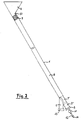
- FIG. 1 and 2 show partially schematic embodiments of conveyor devices according to the invention in cross section.
- an obliquely downwardly extending tube 1 is closed at both ends 2, 3. Near the upper end 2, a filler neck 4 opens from the top of the tube 1.
- a plug 7 which largely fills the internal cross section, is movably arranged via a thread 8 between a stop 10 just below the filler neck 4 and the lower end 3 of the tube.
- the reference symbols 7 'and 7 "indicate two further layers of the plug.
- the thread 8 can be moved by a schematically indicated winch 9.
- the tube 1 of the embodiment shown in FIG. 2 ends at the top in a filler neck 4. Shortly before the lower end 3 of the tube 1, an outlet neck 5 is provided, which can be closed by a shut-off element 13. At the lower end 3, a compressed air line 14 with a shut-off valve 12 and a pressure reducer 11 is connected to the pipe 1.
- the plug 7, which largely fills the inner cross section of the tube 1, can be moved between a stop 10 below the filler neck 4 and the lower end 3 of the tube by means of compressed air which can be introduced through the compressed air line.
- plug 7 is located at or near the upper stop 10. As material is supplied, plug 7 is lowered in the direction of the lower end 3 of the pipe 1 by controlling the compressed air flow accordingly.
- the shut-off device 13 is opened.
- the plug 7 is lowered into the lower end position 7 ", the transported material leaves the pipe 1 via the outlet connection 5.
- the plug 7 is moved again until the stop 10 at the upper pipe end.
Abstract
Description
Die Erfindung bezieht sich auf eine Vorrichtung zur Förderung mechanisch empfindlicher kleinstückiger Güter über ein schräg abwärts verlaufendes geschlossenes Rohr.The invention relates to a device for conveying mechanically sensitive small-piece goods over a closed tube running obliquely downwards.
Auf vielen Gebieten der Technik besteht das Problem, empfindliche kleinstückige Güter von einem höhergelegenen Niveau auf ein tiefergelegenes Niveau zu fördern. Beispielsweise ist es in der großtechnischen pharmazeutischen Produktion des öfteren erforderlich, feste Darreichungsformen, wie z.B. Tabletten, Filmtabletten, Dragees und Kapseln, in vertikaler Richtung von oben nach unten unter Ausnutzung der Schwerkraft zu fördern. Solange nur Niveauunterschiede von 300 bis 500 mm zu überwinden sind, ist in der Regel bei Verwendung von Fallrohren noch nicht mit untolerierbaren mechanischen Einwirkungen auf die Darreichungsformen zu rechnen. Bei größeren Höhendifferenzen ist jedoch mit einer erheblichen mechanischen Belastung zu rechnen, die zu unerwünschtem Abrieb oder Bruch führen kann. Anstelle von Fallrohren müssen in solchen Fällen deshalb Behältnisse zum Transport des empfindlichen Fördergutes eingesetzt werden, was relativ aufwendig ist.In many areas of technology there is the problem of conveying delicate small-sized goods from a higher level to a lower level. For example, in large-scale pharmaceutical production it is often necessary to use solid dosage forms, e.g. To promote tablets, film-coated tablets, dragees and capsules in a vertical direction from top to bottom using gravity. As long as there are only level differences of 300 to 500 mm to be overcome, the use of downspouts does not usually result in intolerable mechanical effects on the dosage forms. With larger height differences, however, a considerable mechanical load can be expected, which can lead to undesired abrasion or breakage. Instead of downpipes, containers have to be used to transport the sensitive material to be conveyed in such cases, which is relatively complex.
In der DE-PS 4041706 wird vorgeschlagen, bei der Förderung von Tabletten über Förderrohre von einem höhergelegenen Ort in tiefergelegene Transportbehälter in den Förderrohren eine von unten nach oben gerichtete Luftströmung zu erzeugen, so daß die Tabletten entgegen dem Widerstand des Luftstromes langsam nach unten sinken. Nachteilig an diesem Verfahren ist die schwierige Steuerung und Anpassung des Luftstromes an das zu fördernde Gut sowie die insbesondere im Falle des Auftretens von Turbulenzen zu beobachtende mechanische Belastung des Fördergutes.In DE-PS 4041706 it is proposed to produce a bottom-up air flow when conveying tablets via conveyor tubes from a higher location to lower-lying transport containers in the conveyor tubes, so that the tablets slowly sink downward against the resistance of the airflow. A disadvantage of this method is the difficult control and adaptation of the air flow to the material to be conveyed and the mechanical load on the material to be observed, particularly in the event of turbulence.
Die der vorliegenden Erfindung zugrundeliegende Aufgabe wird in der Zurverfügungstellung einer Vorrichtung zur Förderung mechanisch empfindlicher kleinstückiger Güter von einem höheren Niveau auf ein tiefergelegenes Niveau gesehen, die sich durch eine qualitätsschonende Förderung auch über große Höhendifferenzen, eine wenig aufwendige Handhabung und Eignung für unterschiedliches Fördergut ohne die Notwendigkeit besonderer Anpassungsmaßnahmen auszeichnet.The object on which the present invention is based is seen in the provision of a device for conveying mechanically sensitive small-sized goods from a higher level to a lower level, which is characterized by quality-friendly conveyance even over large height differences, less complex handling and suitability for different conveyed goods without the The need for special adaptation measures.
Gelöst wird diese Aufgabe durch ein schräg verlaufendes Rohr, das an beiden Enden verschlossen ist, dessen oben gelegenes Ende einen Einfüllstutzen, dessen unten gelegenen Ende einen im wesentlichen senkrecht nach unten verlaufenden seitlichen Auslaufstutzen, sowie im Rohrinneren einen zwischen den beiden Enden des Rohres hin und her bewegbaren, den Innenquerschnitt des Rohres weitgehend ausfüllenden Pfropfen aufweist.This object is achieved by an obliquely running tube which is closed at both ends, the top end of which is a filler neck, the bottom end of which is a substantially vertically downward lateral outlet neck, and inside the tube one between the two ends of the tube forth movable plug that largely fills the inner cross section of the tube.
Gegenstand der Erfindung ist daher eine Vorrichtung zur Förderung mechanisch empfindlicher kleinstückiger Güter über ein schräg abwärts verlaufendes geschlossenes Rohr, die dadurch gekennzeichnet ist, daß das schräg verlaufende Rohr an beiden Enden verschlossen ist, beim oben gelegenen Ende einen Einfüllstutzen, beim unten gelegenen Ende einen im wesentlichen senkrecht nach unten verlaufenden seitlichen Auslaufstutzen, sowie einen im Rohrinneren zwischen den beiden Enden des Rohres hin und her bewegbaren, den Innenquerschnitt des Rohres weitgehend ausfüllenden Pfropfen aufweist.The invention therefore relates to a device for conveying mechanically sensitive small-piece goods via an obliquely downwardly extending closed tube, which is characterized in that the obliquely extending tube is closed at both ends, a filler neck at the upper end, and an im at the lower end has essentially vertical downward outlet spout, and has a plug which can be moved back and forth in the interior of the tube between the two ends of the tube and largely fills the inner cross section of the tube.
Weitere Gegenstände ergeben sich aus den Patentansprüchen.Further subjects emerge from the patent claims.
Die Bewegung des Pfropfens kann auf übliche Weise über einen Faden manuell oder automatisch über eine Seilwinde mit Antriebsaggregat oder mittels Druckluft erfolgen. Zu Beginn des Eintrags von Fördergut durch den Einfüllstutzen steht der bewegliche Pfropfen knapp unterhalb des Einfüllstutzens, wo ein die weitere Bewegung des Pfropfens nach oben begrenzender Anschlag vorgesehen sein kann. Entsprechend der Menge des durch den Einfüllstutzen eintretenden Fördergutes wird der Pfropfen nach unten bewegt. Sobald der Pfropfen sich über die Öffnung des Auslaufstutzens hinwegbewegt, entleert sich das schräg abwärts verlaufende Rohr. Nach Entleerung der Rohres wird der Pfropfen wieder bis knapp unterhalb den Einfüllstutzen bewegt, damit sich erneut eine Säule von Fördergut aufbauen kann, die mit geeigneter Geschwindigkeit gesteuert durch die Abwärtsbewegung des Pfropfens in Richtung auf den Auslaufstutzen bewegt wird. Es ist zweckmäßig, die Bewegung des Pfropfens selbsttätig in Abhängigkeit von der Menge des durch den Einfüllstutzen eintretenden Fördergutes zu regeln. Die Bewegung des Pfropfens kann beispielsweise durch die Leistung der das Fördergut produzierenden Vorrichtungen, wie beispielsweise Tablettenpressen, oder die Geschwindigkeit nachgeschalteter Vorrichtungen für die weitere Verarbeitung, wie beispielsweise Konfektionierungslinien, gesteuert werden. Es versteht sich von selbst, daß die erfindungsgemäße Vorrichtung mit Sensoren zur Überwachung und Steuerung des Flusses des Fördergutes, wie beispielsweise Lichtschranken, ausgerüstet werden kann.The plug can be moved in the usual way using a thread, manually or automatically using a cable winch with a drive unit or using compressed air. At the beginning of the entry of material to be conveyed through the filler neck, the movable stopper is located just below the filler neck, where a stop which limits the further movement of the stopper can be provided. The stopper is moved downwards in accordance with the quantity of material to be conveyed entering through the filler neck. As soon as the stopper moves over the opening of the spout, the obliquely downward pipe is emptied. After the tube has been emptied, the stopper is moved again to just below the filler neck so that a column of material to be conveyed can be built up again, which is controlled at a suitable speed by the downward movement of the stopper in the direction of the outlet neck. It is advisable to regulate the movement of the plug automatically depending on the amount of material to be conveyed entering through the filler neck. The movement of the graft can be controlled, for example, by the performance of the devices producing the material to be conveyed, such as tablet presses, or the speed of downstream devices for further processing, such as, for example, assembly lines. It goes without saying that the device according to the invention can be equipped with sensors for monitoring and controlling the flow of the conveyed material, such as light barriers.
In einer besonderen Ausführungsform können der Einfüllstutzen und/oder der Auslaufstutzen mit Einrichtungen zum manuellen oder selbsttätigen Andocken an Fördergut liefernde bzw. abnehmende Vorrichtungen ausgestattet sein. In einer als Beispiel angegebenen erfindungsgemäßen Ausführungsform ist das schräge Rohr als Plexiglasrohr von ca. 4 m Länge und ca. 70 mm Durchmesser ausgeführt, das mit einer Neigung von etwa 45 Grad in einer an der Decke abgehangenen beweglichen Haltevorrichtung arretiert ist.In a special embodiment, the filler neck and / or the outlet neck can be equipped with devices for manual or automatic docking on devices that deliver or remove items to be conveyed. In an embodiment according to the invention given as an example, the oblique tube is designed as a plexiglass tube of approximately 4 m in length and approximately 70 mm in diameter, which is locked at an inclination of approximately 45 degrees in a movable holding device suspended from the ceiling.
Fig. 1 und 2 zeigen teilweise schematisch Ausführungsformen erfindungsgemäßer Fördervorrichtungen im Querschnitt.1 and 2 show partially schematic embodiments of conveyor devices according to the invention in cross section.
In der Ausführungsform nach Fig. 1 ist ein schräg abwärts verlaufendes Rohr 1 an beiden Enden 2, 3 verschlossen. Nahe beim oberen Ende 2 mündet von oben her ein Einfüllstutzen 4 am Rohr 1. Kurz vor dem unteren Ende 3 ist ein nach unten verlaufender Auslaßstutzen 5 vorgesehen. Im Innern 6 des Rohres ist ein den Innenquerschnitt weitgehend ausfüllender Pfropfen 7 über einen Faden 8 zwischen einem Anschlag 10 knapp unterhalb des Einfüllstutzens 4 und dem unteren Ende 3 des Rohres bewegbar angeordnet. Mit den Bezugszeichen 7' und 7" sind zwei weitere Lagen des Pfropfens angedeutet. Der Faden 8 ist durch eine schematisch angegebene Seilwinde 9 bewegbar.In the embodiment according to FIG. 1, an obliquely downwardly extending
Das Rohr 1 der in Fig. 2 dargestellten Ausführungsform endet oben in einem Einfüllstutzen 4. Kurz vor dem unteren Ende 3 des Rohres 1 ist ein Auslaßstutzen 5 vorgesehen, der durch ein Absperrorgan 13 verschließbar ist. Am unteren Ende 3 ist eine Druckluftleitung 14 mit einem Absperrventil 12 und einem Druckminderer 11 an das Rohr 1 angeschlossen. Der den Innenquerschnitt des Rohres 1 weitgehend ausfüllende Pfropfen 7 ist zwischen einem Anschlag 10 unterhalb des Einfüllstutzens 4 und dem unteren Ende 3 des Rohres mittels durch die Druckluftleitung einbringbare Druckluft bewegbar. Zu Beginn des Einfüllens von zu transportierendem Material befindet sich Pfropfen 7 am oder nahe dem oberen Anschlag 10. In dem Maße wie Material zugeführt wird, wird Pfropfen 7 durch entsprechende Steuerung des Druckluftstroms in Richtung auf das untere Ende 3 des Rohres 1 abgesenkt. Sobald Pfropfen 7 in Höhe des Auslaßstutzens 5 angelangt ist (Stellung 7'), wird das Absperrorgan 13 geöffnet. Mit dem Absenken des Pfropfens 7 in die untere Endstellung 7" verläßt das transportierte Material das Rohr 1 über den Auslaßstutzen 5. Nach Verschließen des Absperrorgans 13 wird Pfropfen 7 erneut bis zum Anschlag 10 am oberen Rohrende bewegt.The
Claims (5)
Applications Claiming Priority (2)
| Application Number | Priority Date | Filing Date | Title |
|---|---|---|---|
| DE1995105255 DE19505255C2 (en) | 1995-02-16 | 1995-02-16 | Device for conveying small pieces |
| DE19505255 | 1995-02-16 |
Publications (2)
| Publication Number | Publication Date |
|---|---|
| EP0727366A2 true EP0727366A2 (en) | 1996-08-21 |
| EP0727366A3 EP0727366A3 (en) | 1998-03-18 |
Family
ID=7754163
Family Applications (1)
| Application Number | Title | Priority Date | Filing Date |
|---|---|---|---|
| EP96102157A Ceased EP0727366A3 (en) | 1995-02-16 | 1996-02-14 | Device for transporting small pieces |
Country Status (2)
| Country | Link |
|---|---|
| EP (1) | EP0727366A3 (en) |
| DE (1) | DE19505255C2 (en) |
Cited By (2)
| Publication number | Priority date | Publication date | Assignee | Title |
|---|---|---|---|---|
| WO2003074395A1 (en) * | 2002-03-06 | 2003-09-12 | Matcon (R & D) Limited | Apparatus for transferring flowable material |
| WO2007011283A1 (en) * | 2005-07-15 | 2007-01-25 | Astrazeneca Ab | A method for transporting a particulate material and a transportation device for a particulate material |
Families Citing this family (1)
| Publication number | Priority date | Publication date | Assignee | Title |
|---|---|---|---|---|
| DE10323056B4 (en) * | 2003-05-20 | 2006-07-06 | Rainer Klumpp | conveyor system |
Citations (2)
| Publication number | Priority date | Publication date | Assignee | Title |
|---|---|---|---|---|
| EP0165473A2 (en) * | 1984-06-21 | 1985-12-27 | International Business Machines Corporation | Workpiece transfer track |
| DE4041706C1 (en) * | 1990-12-24 | 1991-12-12 | L. B. Bohle Pharmatechnik Gmbh, 4722 Ennigerloh, De | Charging storage or transport containers with tablets - from elevated position via telescopic feed pipe |
Family Cites Families (1)
| Publication number | Priority date | Publication date | Assignee | Title |
|---|---|---|---|---|
| DE7404393U (en) * | 1974-05-16 | Siemens Ag | Pneumatic tube |
-
1995
- 1995-02-16 DE DE1995105255 patent/DE19505255C2/en not_active Expired - Fee Related
-
1996
- 1996-02-14 EP EP96102157A patent/EP0727366A3/en not_active Ceased
Patent Citations (2)
| Publication number | Priority date | Publication date | Assignee | Title |
|---|---|---|---|---|
| EP0165473A2 (en) * | 1984-06-21 | 1985-12-27 | International Business Machines Corporation | Workpiece transfer track |
| DE4041706C1 (en) * | 1990-12-24 | 1991-12-12 | L. B. Bohle Pharmatechnik Gmbh, 4722 Ennigerloh, De | Charging storage or transport containers with tablets - from elevated position via telescopic feed pipe |
Cited By (3)
| Publication number | Priority date | Publication date | Assignee | Title |
|---|---|---|---|---|
| WO2003074395A1 (en) * | 2002-03-06 | 2003-09-12 | Matcon (R & D) Limited | Apparatus for transferring flowable material |
| US7077261B2 (en) | 2002-03-06 | 2006-07-18 | Matcon (R&D) Limited | Apparatus for transferring flowable material |
| WO2007011283A1 (en) * | 2005-07-15 | 2007-01-25 | Astrazeneca Ab | A method for transporting a particulate material and a transportation device for a particulate material |
Also Published As
| Publication number | Publication date |
|---|---|
| DE19505255C2 (en) | 1996-12-05 |
| DE19505255A1 (en) | 1996-08-22 |
| EP0727366A3 (en) | 1998-03-18 |
Similar Documents
| Publication | Publication Date | Title |
|---|---|---|
| DE2235747A1 (en) | METHOD AND DEVICE FOR LOADING BULK GOODS | |
| DE3727561A1 (en) | DEVICE FOR LOADING A SILO VEHICLE OR THE LIKE WITH GIANT CAPABILITY | |
| EP0727366A2 (en) | Device for transporting small pieces | |
| DE3708653C2 (en) | Loading device for loose loading of dusty bulk goods | |
| EP3453648A1 (en) | Inlet device | |
| DE3613394A1 (en) | Process and apparatus for the filling of large bags | |
| EP0624412B1 (en) | Device for the continuous addition of powdery or granular casting agents to the surface of a melt in a continuous casting mould | |
| DE202005019112U1 (en) | Unit for separating of frozen piece goods has transporting speeds adjusted to piece goods by means of controllable and/or governable buffer units for purpose of effecting unhindered transporting flow of piece goods | |
| DE2701343A1 (en) | EQUIPMENT FOR LOADING RAILWAYS, TRUCKS AND CONTAINERS IN GENERAL WITH LOOSE MATERIALS | |
| DE3524291C2 (en) | Picking device for goods | |
| DE598438C (en) | Device for the continuous conveyance of grainy bulk goods, especially concrete and. Like., by means of air | |
| EP0473941A1 (en) | Method for conveying oxygen sensitive, powdered or grained bulk material and means for that | |
| DE4330796A1 (en) | Apparatus for transferring a wide stream of conveyed material to a single-track stream of conveyed material to be discharged | |
| WO2004106199A1 (en) | Device for continuously feeding a powdery solid into a pneumatic conveying line | |
| DE2219914C3 (en) | Feeding and dosing system | |
| DE3810191A1 (en) | COMPRESSED AIR EMPTYING DEVICE FOR A BOTTLE CONTAINER WITH AT LEAST TWO DRAINING OPENINGS AND A METHOD FOR EMPTYING THE CONTAINER | |
| DE1102650B (en) | Pneumatic conveyor for conveying bulk goods by means of compressed air from a container into a pipeline | |
| DE3011954C2 (en) | Suspension for top removal devices | |
| DE1506965A1 (en) | Method and device for pneumatic conveying and dosing of granular and powdery substances, in particular granules | |
| DE3012047C2 (en) | Dosing device for conveying liquid metal | |
| DE19541674A1 (en) | Device for feeding tablets for pharmaceutical purposes or another similar loose product between work units arranged on different levels | |
| DE3408271A1 (en) | Device for the pneumatic vertical conveying of conveyed material such as grain | |
| EP1429982B1 (en) | Pneumatic conveyor device | |
| DE6607956U (en) | DEVICE FOR PNEUMATIC CONVEYING AND DOSING OF GRAINY AND POWDERED SUBSTANCES, IN PARTICULAR GRANULATES. | |
| DE422741C (en) | Conveyor vessel for the automatic conveyance of bulk goods |
Legal Events
| Date | Code | Title | Description |
|---|---|---|---|
| PUAI | Public reference made under article 153(3) epc to a published international application that has entered the european phase |
Free format text: ORIGINAL CODE: 0009012 |
|
| 17P | Request for examination filed |
Effective date: 19960220 |
|
| AK | Designated contracting states |
Kind code of ref document: A2 Designated state(s): DE ES FR GB IT |
|
| PUAL | Search report despatched |
Free format text: ORIGINAL CODE: 0009013 |
|
| AK | Designated contracting states |
Kind code of ref document: A3 Designated state(s): DE ES FR GB IT |
|
| GRAG | Despatch of communication of intention to grant |
Free format text: ORIGINAL CODE: EPIDOS AGRA |
|
| 17Q | First examination report despatched |
Effective date: 19990201 |
|
| STAA | Information on the status of an ep patent application or granted ep patent |
Free format text: STATUS: THE APPLICATION HAS BEEN REFUSED |
|
| 18R | Application refused |
Effective date: 19990920 |