EP0726736B1 - Vorgefüllte fluidspritze - Google Patents
Vorgefüllte fluidspritze Download PDFInfo
- Publication number
- EP0726736B1 EP0726736B1 EP94932149A EP94932149A EP0726736B1 EP 0726736 B1 EP0726736 B1 EP 0726736B1 EP 94932149 A EP94932149 A EP 94932149A EP 94932149 A EP94932149 A EP 94932149A EP 0726736 B1 EP0726736 B1 EP 0726736B1
- Authority
- EP
- European Patent Office
- Prior art keywords
- syringe
- chamber
- reservoir
- outlet
- bellows
- Prior art date
- Legal status (The legal status is an assumption and is not a legal conclusion. Google has not performed a legal analysis and makes no representation as to the accuracy of the status listed.)
- Expired - Lifetime
Links
- 239000012530 fluid Substances 0.000 title claims abstract description 32
- 239000007788 liquid Substances 0.000 claims abstract description 50
- 238000004891 communication Methods 0.000 claims abstract description 16
- 230000008878 coupling Effects 0.000 claims description 12
- 238000010168 coupling process Methods 0.000 claims description 12
- 238000005859 coupling reaction Methods 0.000 claims description 12
- 230000006835 compression Effects 0.000 claims description 4
- 238000007906 compression Methods 0.000 claims description 4
- 238000010926 purge Methods 0.000 claims description 4
- 238000010992 reflux Methods 0.000 claims 1
- 239000007789 gas Substances 0.000 description 19
- 239000003708 ampul Substances 0.000 description 14
- 229940079593 drug Drugs 0.000 description 13
- 239000003814 drug Substances 0.000 description 13
- 210000003811 finger Anatomy 0.000 description 10
- 239000004033 plastic Substances 0.000 description 7
- 229940071643 prefilled syringe Drugs 0.000 description 7
- 206010015137 Eructation Diseases 0.000 description 6
- 238000000034 method Methods 0.000 description 6
- 210000003462 vein Anatomy 0.000 description 6
- 239000008280 blood Substances 0.000 description 5
- 210000004369 blood Anatomy 0.000 description 5
- 208000012266 Needlestick injury Diseases 0.000 description 4
- 239000000356 contaminant Substances 0.000 description 4
- 238000002347 injection Methods 0.000 description 4
- 239000007924 injection Substances 0.000 description 4
- 238000004519 manufacturing process Methods 0.000 description 4
- 210000005224 forefinger Anatomy 0.000 description 3
- 238000010079 rubber tapping Methods 0.000 description 3
- 206010053567 Coagulopathies Diseases 0.000 description 2
- 238000005452 bending Methods 0.000 description 2
- 230000035602 clotting Effects 0.000 description 2
- 210000003813 thumb Anatomy 0.000 description 2
- 229940034610 toothpaste Drugs 0.000 description 2
- 239000000606 toothpaste Substances 0.000 description 2
- UCTWMZQNUQWSLP-VIFPVBQESA-N (R)-adrenaline Chemical compound CNC[C@H](O)C1=CC=C(O)C(O)=C1 UCTWMZQNUQWSLP-VIFPVBQESA-N 0.000 description 1
- 229930182837 (R)-adrenaline Natural products 0.000 description 1
- 241000282461 Canis lupus Species 0.000 description 1
- 208000010496 Heart Arrest Diseases 0.000 description 1
- 208000007536 Thrombosis Diseases 0.000 description 1
- 230000001154 acute effect Effects 0.000 description 1
- 230000006978 adaptation Effects 0.000 description 1
- 238000005273 aeration Methods 0.000 description 1
- 230000003321 amplification Effects 0.000 description 1
- 229940127090 anticoagulant agent Drugs 0.000 description 1
- 238000000071 blow moulding Methods 0.000 description 1
- 239000006227 byproduct Substances 0.000 description 1
- 230000000747 cardiac effect Effects 0.000 description 1
- 230000008859 change Effects 0.000 description 1
- 230000001010 compromised effect Effects 0.000 description 1
- 238000010276 construction Methods 0.000 description 1
- 238000005520 cutting process Methods 0.000 description 1
- 230000001419 dependent effect Effects 0.000 description 1
- 238000013461 design Methods 0.000 description 1
- 229910003460 diamond Inorganic materials 0.000 description 1
- 239000010432 diamond Substances 0.000 description 1
- 201000010099 disease Diseases 0.000 description 1
- 208000037265 diseases, disorders, signs and symptoms Diseases 0.000 description 1
- 229960005139 epinephrine Drugs 0.000 description 1
- 230000003203 everyday effect Effects 0.000 description 1
- 238000005429 filling process Methods 0.000 description 1
- 239000002920 hazardous waste Substances 0.000 description 1
- 238000001802 infusion Methods 0.000 description 1
- 238000003780 insertion Methods 0.000 description 1
- 230000037431 insertion Effects 0.000 description 1
- 238000010253 intravenous injection Methods 0.000 description 1
- 239000000463 material Substances 0.000 description 1
- 239000002906 medical waste Substances 0.000 description 1
- 230000005499 meniscus Effects 0.000 description 1
- 238000012986 modification Methods 0.000 description 1
- 230000004048 modification Effects 0.000 description 1
- 238000003199 nucleic acid amplification method Methods 0.000 description 1
- 244000052769 pathogen Species 0.000 description 1
- 230000000737 periodic effect Effects 0.000 description 1
- 230000008569 process Effects 0.000 description 1
- 238000012545 processing Methods 0.000 description 1
- 239000010832 regulated medical waste Substances 0.000 description 1
- 230000035945 sensitivity Effects 0.000 description 1
- 238000012163 sequencing technique Methods 0.000 description 1
- 239000000243 solution Substances 0.000 description 1
- 238000003892 spreading Methods 0.000 description 1
- 230000007480 spreading Effects 0.000 description 1
- 230000001954 sterilising effect Effects 0.000 description 1
- 238000003860 storage Methods 0.000 description 1
- 230000007704 transition Effects 0.000 description 1
Images

Classifications
-
- A—HUMAN NECESSITIES
- A61—MEDICAL OR VETERINARY SCIENCE; HYGIENE
- A61M—DEVICES FOR INTRODUCING MEDIA INTO, OR ONTO, THE BODY; DEVICES FOR TRANSDUCING BODY MEDIA OR FOR TAKING MEDIA FROM THE BODY; DEVICES FOR PRODUCING OR ENDING SLEEP OR STUPOR
- A61M5/00—Devices for bringing media into the body in a subcutaneous, intra-vascular or intramuscular way; Accessories therefor, e.g. filling or cleaning devices, arm-rests
- A61M5/178—Syringes
- A61M5/28—Syringe ampoules or carpules, i.e. ampoules or carpules provided with a needle
- A61M5/281—Syringe ampoules or carpules, i.e. ampoules or carpules provided with a needle using emptying means to expel or eject media, e.g. pistons, deformation of the ampoule, or telescoping of the ampoule
- A61M5/282—Syringe ampoules or carpules, i.e. ampoules or carpules provided with a needle using emptying means to expel or eject media, e.g. pistons, deformation of the ampoule, or telescoping of the ampoule by compression of deformable ampoule or carpule wall
-
- B—PERFORMING OPERATIONS; TRANSPORTING
- B65—CONVEYING; PACKING; STORING; HANDLING THIN OR FILAMENTARY MATERIAL
- B65B—MACHINES, APPARATUS OR DEVICES FOR, OR METHODS OF, PACKAGING ARTICLES OR MATERIALS; UNPACKING
- B65B3/00—Packaging plastic material, semiliquids, liquids or mixed solids and liquids, in individual containers or receptacles, e.g. bags, sacks, boxes, cartons, cans, or jars
- B65B3/003—Filling medical containers such as ampoules, vials, syringes or the like
- B65B3/006—Related operations, e.g. scoring ampoules
-
- A—HUMAN NECESSITIES
- A61—MEDICAL OR VETERINARY SCIENCE; HYGIENE
- A61M—DEVICES FOR INTRODUCING MEDIA INTO, OR ONTO, THE BODY; DEVICES FOR TRANSDUCING BODY MEDIA OR FOR TAKING MEDIA FROM THE BODY; DEVICES FOR PRODUCING OR ENDING SLEEP OR STUPOR
- A61M5/00—Devices for bringing media into the body in a subcutaneous, intra-vascular or intramuscular way; Accessories therefor, e.g. filling or cleaning devices, arm-rests
- A61M5/178—Syringes
- A61M5/31—Details
- A61M2005/3117—Means preventing contamination of the medicament compartment of a syringe
- A61M2005/3118—Means preventing contamination of the medicament compartment of a syringe via the distal end of a syringe, i.e. syringe end for mounting a needle cannula
-
- A—HUMAN NECESSITIES
- A61—MEDICAL OR VETERINARY SCIENCE; HYGIENE
- A61M—DEVICES FOR INTRODUCING MEDIA INTO, OR ONTO, THE BODY; DEVICES FOR TRANSDUCING BODY MEDIA OR FOR TAKING MEDIA FROM THE BODY; DEVICES FOR PRODUCING OR ENDING SLEEP OR STUPOR
- A61M5/00—Devices for bringing media into the body in a subcutaneous, intra-vascular or intramuscular way; Accessories therefor, e.g. filling or cleaning devices, arm-rests
- A61M5/178—Syringes
- A61M5/31—Details
- A61M2005/3117—Means preventing contamination of the medicament compartment of a syringe
- A61M2005/3118—Means preventing contamination of the medicament compartment of a syringe via the distal end of a syringe, i.e. syringe end for mounting a needle cannula
- A61M2005/312—Means preventing contamination of the medicament compartment of a syringe via the distal end of a syringe, i.e. syringe end for mounting a needle cannula comprising sealing means, e.g. severable caps, to be removed prior to injection by, e.g. tearing or twisting
-
- A—HUMAN NECESSITIES
- A61—MEDICAL OR VETERINARY SCIENCE; HYGIENE
- A61M—DEVICES FOR INTRODUCING MEDIA INTO, OR ONTO, THE BODY; DEVICES FOR TRANSDUCING BODY MEDIA OR FOR TAKING MEDIA FROM THE BODY; DEVICES FOR PRODUCING OR ENDING SLEEP OR STUPOR
- A61M5/00—Devices for bringing media into the body in a subcutaneous, intra-vascular or intramuscular way; Accessories therefor, e.g. filling or cleaning devices, arm-rests
- A61M5/178—Syringes
- A61M5/31—Details
- A61M2005/3123—Details having air entrapping or venting means, e.g. purging channels in pistons
Definitions
- This invention relates to dose administering devices. More specifically, the following invention is directed to a syringe which is prefilled with a liquid that can be used either in a needleless system or with needles to administer fluids in a medical environment.
- syringes provide frequent risk when manipulated in their intended use, also unfortunately sometimes during unintended reuse and always during disposal.
- the syringe is packaged empty and must be filled by fluid communication with an ampoule.
- the ampoule is configured as a container sealed by a rubber dam which is to be perforated by a needle attached to the syringe.
- the contents within the ampoule is in an air-tight container. Consequently, one extracting a dose of fluid from the ampoule will generate a negative pressure if the syringe is first inserted into the ampoule while the piston of the syringe is in a fully "closed" position, i.e. no air space exists between the piston and the needle carried on the cylinder.
- many people who use syringes to extract fluids from ampoules will begin with the piston of the syringe in an intermediate position and push air into the ampoule creating a positive pressure. This makes it easier to withdraw fluid from the ampoule.
- the air that is thus injected into the ampoule is a contaminant, since normal air in an every day environment is filled with particulate contaminants which necessarily become transmitted into the ampoule. In a medical care environment, such as in a hospital or doctor's office, it may even be more likely that the contaminant could foster pathogens. Thus, subsequent users of the ampoule are faced with the real possibility that a contaminant injected into the ampoule during a prior excursion into the ampoule will be passed onto a subsequent user of the medication.
- the conventional syringe utilizes a piston which reciprocates within a cylinder, the conventional syringe adapts itself to reuse multiple times. There is no impediment inherent in the construction of a syringe which precludes its subsequent use by others. It is common knowledge and has been widely reported that reuse by third parties provides unwanted risks in spreading disease.
- the needle In all cases, in order to effectively utilize the syringe, the needle must first have been placed on the syringe body. This is typically performed by a luer coupling which unites a base of the needle to a tip of the syringe. Once the syringe has been equipped with the needle, extraordinary care must be exercised to prevent unwanted needle sticks such as described earlier. Frequently, the syringe is loaded with medicating fluid at a site remote from the patient who is to receive the dose. When this is the case, a syringe equipped with a needle must be transported to the patient. Most systems provide for a needle cap to be placed back over the needle to guard against unintended contact. Problems with inadvertent needle sticks when replacing a needle cap are quite common.
- a certain degree of tactile feedback can be perceivable when using a conventional syringe. Since the cross-section of the liquid changes as it moves from the cylindrical portion of the syringe through its tapering conical section at the outlet, the liquid's velocity increases as it is forced out of the syringe. Should an uncharacteristic resistance be perceived during an injection into a catheter, care must be taken that a blood dot is not being dislodged. Blood thinning agents would then have to be administered or, alternatively, if the clot is still perceived connected to the catheter, the catheter should be removed in favor of a new catheter. When a "long line" catheter system is used, appreciable time and resources of the hospital staff will have been required to reinstall the long line, which sometimes spans from a patient's leg into the patient's heart.
- the present invention is directed to a prefilled fluid syringe comprising, in combination;
- the instant invention has certain attributes which distinguish itself over the known prior art.
- the syringe according to the present invention is not a two piece system since it does not involve a piston and cylinder arrangement in a conventional sense; rather it is a one piece system formed as a container having walls which can deform in a controlled fashion to dispense liquid.
- the liquid contained within the syringe is prefilled at a site remote from the administration of the dose to a patient.
- the syringe is prefilled at a pharmaceutical factory.
- there is no intermediate step where one is required to fill a syringe from an ampoule. There is thus no need to transport the syringe with its needle connected until it is time to administer the dose.
- no needle is even required because the luer coupling of the syringe can dock with a complemental fitting on the catheter.
- the walls of the syringe collapse when ejecting the fluid.
- the syringe does not lend itself to multiple or subsequent reuses since the final configuration of the syringe is collapsed. Refilling the syringe would be analogous to trying to "get toothpaste back into a toothpaste tube”.
- the syringe Because the syringe is prefilled, it can be labeled with the contents of the medication. Thus, the chances of transposing syringes and administering an inappropriate dose to a patient will have been minimized.
- the instant invention includes a bellows-type diaphragm at one end.
- the diaphragm serves as a main reservoir for the fluid.
- the reservoir communicates with a tapering section which ultimately communicates with a luer-type coupling.
- the coupling has an outlet which has been temporarily placed in fluid communication with a conduit which in turn leads to a chamber.
- a portion of the chamber may include a tab member thereon provided with indicia correlative of the fluid within the syringe.
- the area where the luer outlet connects to the conduit is provided with a scoreline or other weakened area. This facilitates the removal of the conduit and chamber from the remainder of the syringe.
- sufficient liquid is present within the interior of the device so that liquid will reside initially within both the reservoir and at least a portion of the chamber.
- Air is naturally present when a liquid is filled into a container. Gas such as air will naturally travel with the liquid when it is being placed into the syringe at the factory, since handling of the liquid naturally implicates some aeration as a natural consequence of fluid handling in an automated environment. Moreover, even if it were economically feasible to fill a device without the presence of any air, the costs associated with processing the liquid prior to inclusion within the syringe would involve a needless expense, because the liquid would have to be deaerated and the manufacturing process would have to be in a substantially airfree environment. The air must be accounted for and dealt with when prefilling syringes.
- the syringe has been prefilled at a factory such that sufficient liquid is present to occupy the entire reservoir and all of the tapering section, conduit and at least a portion of the chamber.
- the syringe system can be "burped" to induce all air into the chamber prior to severing the conduit and chamber from the syringe at its luer opening.
- the thus formed syringe is devoid of all gas and is now ready for utilization.
- Other versions are disclosed which can purge air in other analogous manners.
- the structure of the instant invention involves an appreciable step down in the ratio of syringe diameter at its widest (i.e. storage reservoir) compared to its luer type outlet.
- this ratio involves a large diameter (20 - 50 mm.) to a small diameter (.1 - 1 mm.).
- the result is greater sensitivity to the presence of obstructions down stream (e.g. clotting) the outlet (e.g. in a catheter) because of the liquid resistance "amplification" due to the pressure/velocity changes.
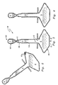
- Figure 1 is a side view of the prefilled fluid syringe according to one form of the present invention.
- Figure 2 is a schematic depiction of figure 1 manipulated in a first way.
- Figure 3 is a schematic depiction of figure 1 manipulated in a second way.
- Figure 4 is a schematic depiction of figure 1 manipulated in a third way.
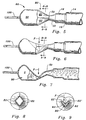
- Figure 5 is a view of one end of the figure 1 cap before severing.
- Figure 6 is a view of one end of the figure 1 cap near severing.
- Figure 7 is a view of one end of the figure 1 cap during severing.
- Figure 8 is a sectional view along lines 8-8 of figure 5.
- Figure 9 is a sectional view along lines 9-9 of figure 6.
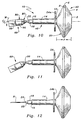
- Figure 10 is a view of one end of the figure 1 cap before severing.
- Figure 11 is a view of one end of the figure 1 cap at severing.
- Figure 12 is a view of one end of the figure 1 cap after severing.
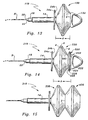
- Figure 13 is a side view of a second embodiment.
- Figure 14 is a side view of a third embodiment.
- Figure 15 is a side view of a fourth embodiment.
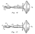
- Figure 16 is a view of one end of the figure 1 cap before severing.
- Figure 17 is a view of one end of the figure 1 cap during severing.
- reference numeral 10 is directed to the prefilled syringe according to one form of the present invention.
- the syringe 10 includes a reservoir 30 which is in operative fluid communication with a scored outlet 50.
- the outlet 50 in turn communicates with a conduit 80 that leads to a chamber 90.
- a tab portion 100 extends from chamber 90 at an end remote from conduit 80. Collectively, the tab 100, chamber 90 and conduit 80 form a type of cap 60 which protects the outlet 50 until the cap 60 is severed from the outlet 50 via the scoreline.
- the tab will include indicia thereon correlative of a liquid contained within the prefilled syringe. This makes more likely that only a proper liquid will be dispensed to the appropriate patient.
- a sequencing operation shown in figures 2 through 4 will be effected. First, the syringe is oriented such that the chamber 90 and tab 100 is at a higher horizontal elevation compared to the reservoir 30 which is at a lower elevation. Next, the syringe 10 is manipulated to assure that all gas bubbles will have migrated up into the air chamber 90. This may be accelerated by tapping the syringe or "burping" the syringe.
- FIG. 10 The right-hand side portion of figure 10 shows a reservoir 30 formed somewhat as a bellows-type diaphragm 20.
- the reservoir 30 encompasses an enclosed volume formed by an end wall 2 which has a circular outer periphery that leads to a conically diverging wall 4.
- the wall 4 communicates with an annular band 6 at one edge thereof. Thereafter, a second edge of the annular band 6 opposite from the diverging wall 4 transitions to a conically converging wall 8 which terminates in a cylindrical section 12 having a constant cross-section and is oriented such that its axial center is coincident with a center of end wall 2.
- the cylindrical section 12 communicates with a finger purchase area 24 which allows one's fingers to be placed on a first face 24a of the purchase area 24 remote from the end wall 2 so that a contracting motion along the direction of the arrows "A" will cause the reservoir to compress, forcing liquid from the cylindrical section 12 and diaphragm 20.
- the finger purchase 24 is substantially disc-shaped and has a hollow central area which allows communication between the cylindrical section 12 and a first tubular section 14 located on the first face side 24a of the purchase area 24 and coaxial with end wall 2 and cylindrical section 12.
- First tubular section 14 has a smaller diameter than cylindrical section 12.
- An end of the tubular section 14 remote from the finger purchase 24 has a tapered portion 16 that leads to another second tubular section 18 having substantially constant circular cross-section, axially aligned with but of a lesser diameter than the first tubular section 14.
- This second tubular section 18 necks-down to an axially aligned converging cone 22 that terminates in the outlet 50 configured as a luer coupling.
- the luer coupling outlet 50 is defined as a scoreline or weakened area.
- Cone 22 thereafter communicates with conduit 80.
- Tab 100 is integrally formed with chamber 90 which communicates with conduit 80.
- Tab 100, chamber 90 and conduit 80 collectively define a cap 60 prior to severing from outlet 50.
- Figures 10 and 11 show a severing sequence. Initially, the syringe appears as in figure 1. Bending moment M, by applying force to the cap 60 about center line C/L, causes fracture of the conduit 80 from cone 22 at scoreline 50 (figure 11).
- Figure 12 shows a needle N installed.
- FIGS. 5 through 9 provide details with respect to one form of the conduit 80, air chamber 90 and tab 100.
- Conduit 80 is formed with plural facets 82. As can be shown in figure 5, preferably facets 82 of the conduit 80 diverge away from the luer coupling outlet 50.
- the converging cone 22 is shown as having a gradually changing diameter along its axial extent.
- a multiplicity of facets 82 define the conduit 80 which expands toward the chamber 90.
- the intent of the facets is to provide one way to crimp the conduit 80 upon severing.
- the additional liquid associated with chamber 90 remains within the chamber 90 rather than seeps out via the conduit 80 after the conduit 80 and chamber 90 have been severed at the outlet 50.
- a means to constrict the conduit 80 by pinching and deforming the conduit 80 is shown.
- FIG 9 One form of constriction is shown in figure 9.
- Four facets are shown in section in figure 8 oriented in a diamond pattern.
- Two facets 82 from figure 8 have been distorted by a force along the direction of the arrow "F" in figure 9 to provide a narrow "heart” shaped constrictive opening. In this manner, the tendency of the liquid to flow outside the conduit 80 will have been impeded.
- the "top" portions of the facets 82' have been distorted into arcuate segments so that the opening 80 is somewhat V-shaped.
- Figure 7 illustrates that the liquid L as well as the gas reside within the chamber 90 just prior to severing at the outlet 50.
- Figures 2 through 4 illustrate diagramatically how the syringe will be purged of all resident gas G and directed to the chamber 90 of the cap 60. It is to be noted that pressure differentials can cause the plastic used in formulating the syringe to admit some gases after manufacture. However, even in the most stringently controlled manufacturing processes, gas is a normal by product when filling containers with liquid and must therefore be taken into account. According to the present method and apparatus, the entrained gas can be directed into the chamber 90 and removed from the liquid contained both within the reservoir 30 and the tubular sections 14, 18.
- FIG. 13 lends itself to such a manipulation.
- a modified form of syringe 110 is shown where reservoir 130 has been changed.
- the modified reservoir 130 includes an end wall 2 similar to the previously discussed embodiment, but also includes compression assisting means in the form of a substantially "D-shaped" pull ring 132.
- the dose administrator will place the fore finger and mid finger of one hand on an outer surface 24a of the finger purchase 24 and the thumb will be placed within the D-ring 132.
- a slight compression of the reservoir bellows 20 will allow a small amount of liquid to be burped from the needle N to assure that liquid is present within the entire cavity of the needle.
- the modified reservoir 230 includes a D-shaped ring 232, but has a "mini-bellows" 220 interposed between the main bellows 230 and the D-ring 232.
- the mini-bellows 220 includes an annular band 226 coupled to a mini-bellows converging wall 228 that connects with what heretofore was (in previous embodiments) an end wall 2, but now is an opening 202 in fluid communication with the interior of the reservoir 230.
- diverging wall 4 connects to converging wall 228.
- a mini-bellows diverging wall 224 is connected to band 226 on a side opposite converging wall 228.
- Wall 224 is sealed off with an end wall 222.
- end wall 222 supports D-ring 232 so that a "two stage" bellows-diaphragm will have been provided.
- bellows 220 and 230 each contain fluid and are in communication at their juncture.
- the needle end can be purged of all air by providing the pressure in the direction of the arrows "A" between front face 24a of the finger purchase 24 and with the thumb inserted in the D-ring 232 as shown in figure 14.
- the structure of the mini-bellows 220 is preferably programmed to "snap" into a first, collapsed position more readily. Therefore, when force is applied along arrow "A", the needle is purged. The syringe is then ready for insertion into a vein.
- any of the bellows such as the mini-bellows 220 can be programmed to collapse more readily than the other bellows by altering certain design variables such as the dimension (width) of the annular band portion (e.g. 226 vis a vis 6), the slope of the walls 224, 228 (vis a vis 4, 8) or perhaps thickness gradations in the plastic itself vis a vis other areas.
- burping or tapping air into cap 60 is not critical since after severing, opening 50 can burp out gas.
- Figure 15 illustrates another scenario in which acute cardiac patients can be treated with premeasured sequential doses of liquid.
- liquid e.g. epinephrine
- FIG. 15 illustrates another scenario in which acute cardiac patients can be treated with premeasured sequential doses of liquid.
- liquid e.g. epinephrine
- successive syringes were required to have been loaded in order to provide sequential doses.
- a series of bellows e.g. a first bellows reservoir 330 is sequentially linked in fluid communication to a second bellows reservoir 430 so that successive doses can be administered as the need arises.
- several doses i.e. in excess of the two reservoirs shown
- the reservoirs can be preprogrammed to collapse in a desired sequence to provide different volumes of liquid.
- a need for medication will have been diagnosed by the medical practitioner.
- the specific medication for the diagnosed need will have been prescribed.
- a syringe will have been selected which has been prefilled with the specific medication.
- the syringe is then oriented such that its liquid reservoir is at a lowermost elevation and an air chamber is at a highest elevation such that the outlet of the syringe is at an elevation intermediate the reservoir and the air chamber.
- the syringe is burped or in other ways encouraged to force all of the air into the chamber.
- the air chamber is separated from the reservoir at the outlet and finally the medication is administered through the outlet.
- This administration can take the form of communication with the syringe or a catheter for example.
- the cap 60 could be first severed before burping out all (or some of) the gas from the syringe interior. Filling the needle and purging out gas could utilize the liquid in the mini-bellows 220.
- Figures 16 and 17 reveal a further method of freeing the cap 60 from the body of the syringe at outlet 50.
- a rotational force R can be applied (optimally at the tab 100) to twist the cap 60 off from the outlet 50.
- the plastic forming the luer coupling at outlet 50 can be programmed for minimal deformation while the cap end (adjacent conduit 80) will have been twisted to a constricted opening.
- a combination of cutting, rotating, bending and flexing could also be used to remove the cap 60 as described above.
Landscapes
- Health & Medical Sciences (AREA)
- Engineering & Computer Science (AREA)
- Hematology (AREA)
- Anesthesiology (AREA)
- Biomedical Technology (AREA)
- Heart & Thoracic Surgery (AREA)
- Vascular Medicine (AREA)
- Life Sciences & Earth Sciences (AREA)
- Animal Behavior & Ethology (AREA)
- General Health & Medical Sciences (AREA)
- Public Health (AREA)
- Veterinary Medicine (AREA)
- Mechanical Engineering (AREA)
- Infusion, Injection, And Reservoir Apparatuses (AREA)
Claims (18)
- Eine vorgefüllte Spritze (10) für Flüssigkeiten, die, in Kombination, folgendes umfaßt:dadurch gekennzeichnet, daß die Auslaßmittel zwischen dem besagten Raum und dem besagten Vorratsbehälter in dem besagten Kanal angeordnet sind, der die flüssigkeitsleitende Verbindung zwischen dem besagten Raum und dem besagten Vorratsbehälter bildet, und nur das Ausstoßen von Flüssigkeit aus der Spritze nach dem Trennen des besagten Vorratsbehälters von dem besagten Raum zulassen und daß die besagten Mittel zum Trennen Mittel sind, die den besagten Vorratsbehälter zusammen mit den besagten Auslaßmitteln von dem besagten Raum trennen.einen Vorratsbehälter (30),einen Raum (90), der über einen Kanal (80) in flüssigkeitsleitender Verbindung mit dem besagten Vorratsbehälter (30) steht,Gas und Flüssigkeit in der besagten Spritze, wobei genügend Flüssigkeit vorhanden ist, um den besagten Vorratsbehälter und den besagten Kanal zu füllen, den besagten Raum aber nur teilweise zu füllen, so daß dieser Gas aufnehmen kann,Mittel, um den besagten Vorratsbehälter von dem besagten Raum zu trennenund Auslaßmittel (50),
- Die Spritze gemäß Anspruch 1, wobei das besagte Mittel zum Trennen des besagten Vorratsbehälters und Auslasses von dem besagtem Raum eine Sollbruchstelle (50) umfaßt.
- Die Spritze gemäß Anspruch 1 oder 2, wobei der besagte Auslaß (50) nach dem Trennen eine Luerkupplung bildet.
- Die Spritze gemäß einem der vorangegangenen Ansprüche, wobei der besagte Raum (90) Anzeigemittel auf einem Teilbereich (100) aufweist, der von den besagten Auslaßmitteln (50) entfernt angeordnet ist, um den Inhalt der Spritze (10) anzuzeigen.
- Die Spritze gemäß einem der vorangegangenen Ansprüche, wobei der besagte Vorratsbehälter (30) als balgenartiges Diaphragma (20) ausgebildet ist, das eine Stirnwand (2) mit einer im wesentlichen kreisförmigen Peripherie aufweist, eine auseinanderlaufende Wand (4), die sich von der besagten Peripherie der besagten Stirnwand (2) aus nach außen erstreckt, ein ringförmiges Band (6), das sich von der besagten auseinanderlaufenden, von der besagten Stirnwand entfernt angeordneten Wand ausgehend erstreckt, und eine konvergierende Wand (8), die sich von einem Rand des besagten ringförmigen Bandes von der besagten auseinanderlaufenden Wand aus erstreckt, wobei der besagte Vorratsbehälter (30) mit darin enthaltener Flüssigkeit versehen ist.
- Die Spritze gemäß Anspruch 5, wobei zur Erleichterung der Handhabung der Spritze ein Fingeranschlag (24) auf der besagten Spritze (10) zwischen dem besagten Diaphragma (20) und dem besagtem Auslaß (50) angeordnet ist.
- Die Spritze gemäß Anspruch 6, die einen ersten röhrenförmigen Abschnitt (14) aufweist, der sich zwischen dem besagtem Fingeranschlag (24) und dem besagtem Auslaß (50) erstreckt.
- Die Spritze gemäß einem der Ansprüche 5 bis 7, die ein an einem Ende des besagten Diaphragmas (130) angeordnetes Kompressionsmittel (132, 232) umfaßt, das das besagte Diaphragma zusammendrückt.
- Die Spritze gemäß einem der Ansprüche 5 bis 8, wobei ein zweites balgenartiges Diaphragma (220) zwischen einem Kompressionsmittel (232) und einem ersten Diaphragma (20) angeordnet ist.
- Die Spritze gemäß einem der Ansprüche 5 bis 8, wobei ein zweites balgenartiges Diaphragma sequentiell in flüssigkeitsleitender Verbindung mit und in Serie mit dem besagten ersten balgenartigen Diaphragma angeordnet ist.
- Die Spritze gemäß einem der Ansprüche 5 bis 10, wobei ein D-Ring (132) an einem Ende des besagten zweiten Diaphragmas (130), von dem besagten Auslaß entfernt, angeordnet ist.
- Die Spritze gemäß einem der vorangegangenen Ansprüche, wobei der besagte Raum (90) ein Rohr (80) aufweist, das sich zwischen dem besagten Raum und den besagten Auslaßmitteln erstreckt.
- Die Spritze gemäß Anspruch 12, wobei das besagte Rohr (80) eine Anzahl von Facetten (82) aufweist, die verformbar sind, um die Rohröffnung zu verschließen.
- Die Spritze gemäß einem der Ansprüche 1-13, die ein Rohr umfaßt, das sich zwischen dem besagten Raum und den besagten Auslaßmitteln erstreckt, und wobei das besagte Rohr eine Anzahl von Facetten (82) aufweist, die verformbar sind, um eine Öffnung, die in dem besagten Rohr nach dem Trennen der besagten Auslaßmittel entstanden ist, zu verschließen.
- Die Spritze gemäß einem der vorangegangenen Ansprüche, wobei der Vorratsbehälter ein Vorratsbehälter für Flüssigkeiten ist und der Raum zur Aufnahme von Gasen/Flüssigkeiten ausgebildet ist.
- Die Spritze gemäß den Ansprüchen 1-13, die einen zusammenklappbaren Balgenteil (230) aufweist, wobei der Balgenteil einen ersten Balgenteil umfaßt, der eine Spülstufe bildet und der nach dem Zusammendrücken einen Teil der im Inneren enthaltenen Flüssigkeit über den Durchlaß ausstößt, um Luft aus dem Apparat zu entfernen, der am äußeren Ende eines Kanülenteils angeordnet ist, und wobei der Balgenteil einen zweiten Balgenteil (220) umfaßt, der eine Spülstufe bildet und der nach dem Zusammendrücken die restliche im Inneren enthaltene Flüssigkeit über den Durchlaß ausstößt.
- Die Spritze gemäß einem der vorangegangenen Ansprüche, die einen Balgenteil umfaßt, in dem Mittel zum Beibehalten des zusammengedrückten Zustandes des Balgenteils vorgesehen sind, um ein Zurückfließen der zuvor ausgetriebenen Flüssigkeit in den Kanülendurchlaßbereich zu verhindern.
- Die Spritze gemäß einem der vorangegangenen Ansprüche, die einen Balgenteil umfaßt, wobei der Balgenteil mit einer vorbestimmten Struktur versehen ist, die bewirkt, daß der Balgenteil durch Inversion kollabiert.
Applications Claiming Priority (3)
| Application Number | Priority Date | Filing Date | Title |
|---|---|---|---|
| US08/147,128 US5538506A (en) | 1993-11-03 | 1993-11-03 | Prefilled fluid syringe |
| US147128 | 1993-11-03 | ||
| PCT/US1994/012613 WO1995012359A1 (en) | 1993-11-03 | 1994-11-02 | Prefilled fluid syringe |
Publications (3)
| Publication Number | Publication Date |
|---|---|
| EP0726736A1 EP0726736A1 (de) | 1996-08-21 |
| EP0726736A4 EP0726736A4 (de) | 1997-07-09 |
| EP0726736B1 true EP0726736B1 (de) | 2003-04-09 |
Family
ID=22520382
Family Applications (1)
| Application Number | Title | Priority Date | Filing Date |
|---|---|---|---|
| EP94932149A Expired - Lifetime EP0726736B1 (de) | 1993-11-03 | 1994-11-02 | Vorgefüllte fluidspritze |
Country Status (6)
| Country | Link |
|---|---|
| US (1) | US5538506A (de) |
| EP (1) | EP0726736B1 (de) |
| AT (1) | ATE236585T1 (de) |
| AU (1) | AU8098194A (de) |
| DE (1) | DE69432476T2 (de) |
| WO (1) | WO1995012359A1 (de) |
Cited By (1)
| Publication number | Priority date | Publication date | Assignee | Title |
|---|---|---|---|---|
| DE10340613A1 (de) * | 2003-08-29 | 2005-03-24 | Primojex Gmbh | Vorrichtung zur Injektion eines injizierbaren Produktes |
Families Citing this family (42)
| Publication number | Priority date | Publication date | Assignee | Title |
|---|---|---|---|---|
| ATE167064T1 (de) * | 1994-10-28 | 1998-06-15 | Schering Ag | Mit fluidem inhalt zu sterilisierenden einmalspritze |
| DE19522451C2 (de) * | 1995-06-21 | 1997-11-06 | Bernd Hansen | Vorrichtung zur Abgabe eines fließfähigen Stoffes aus einem Behälter |
| DE29602173U1 (de) * | 1996-02-08 | 1997-06-26 | B. Braun Melsungen Ag, 34212 Melsungen | Applikationsvorrichtung für medizinische Flüssigkeiten |
| DE19701494A1 (de) * | 1997-01-17 | 1998-07-23 | Boehringer Mannheim Gmbh | Transdermales Injektionssystem |
| USD398396S (en) | 1997-02-28 | 1998-09-15 | Vital Signs, Inc. | Plungerless syringe |
| US6383166B1 (en) | 1997-03-14 | 2002-05-07 | Zephyr Cove | Plungerless syringe: method and apparatus |
| US6019750A (en) | 1997-12-04 | 2000-02-01 | Baxter International Inc. | Sliding reconstitution device with seal |
| US5931816A (en) * | 1998-03-24 | 1999-08-03 | Novinkov; Oleg L. | Syringe and method of using same |
| USD419672S (en) * | 1998-05-08 | 2000-01-25 | Vital Signs Inc. | Plungerless syringe |
| US7074216B2 (en) | 1998-09-15 | 2006-07-11 | Baxter International Inc. | Sliding reconstitution device for a diluent container |
| US7425209B2 (en) | 1998-09-15 | 2008-09-16 | Baxter International Inc. | Sliding reconstitution device for a diluent container |
| US6113583A (en) | 1998-09-15 | 2000-09-05 | Baxter International Inc. | Vial connecting device for a sliding reconstitution device for a diluent container |
| AR021220A1 (es) | 1998-09-15 | 2002-07-03 | Baxter Int | DISPOSITIVO DE CONEXIoN PARA ESTABLECER UNA COMUNICACIoN FLUíDA ENTRE UN PRIMER RECIPIENTE Y UN SEGUNDO RECIPIENTE. |
| US7358505B2 (en) | 1998-09-15 | 2008-04-15 | Baxter International Inc. | Apparatus for fabricating a reconstitution assembly |
| USD441072S1 (en) | 1998-10-21 | 2001-04-24 | Safex, Inc. | Syringe |
| US6134866A (en) * | 1998-12-29 | 2000-10-24 | Vital Signs, Inc. | Apparatus for manufacturing articles |
| USD432647S (en) * | 1999-02-25 | 2000-10-24 | Barry Farris | No reflux syringe |
| US6296150B1 (en) | 1999-02-25 | 2001-10-02 | Barry Farris | Medicinal dosing apparatus and method |
| USD432646S (en) * | 1999-02-26 | 2000-10-24 | Barry Farris | Syringe with air trap |
| ES2169974B1 (es) * | 1999-11-12 | 2003-11-01 | Montoya Albert Fernandez-Arias | Dispositivo para la inyeccion automatica de liquidos. |
| US6764463B1 (en) | 2000-06-27 | 2004-07-20 | Barry Farris | Method and needleless apparatus for the storage of a first substance followed by subsequent mixing with a second substance and transfer without ambient air incursion |
| US6367659B1 (en) | 2000-08-24 | 2002-04-09 | Concept Workshop Worldwide Llc | Telescopic liquid dispenser |
| US6457612B1 (en) * | 2001-10-12 | 2002-10-01 | Amphastar Pharmaceuticals Inc. | Sealable and manipulable pre-filled disposable pipette |
| DE10245318A1 (de) * | 2002-09-27 | 2004-04-08 | Hansen, Bernd, Dipl.-Ing. | Formverfahren, insbesondere Blas- und/oder Vakuumformverfahren, zum Herstellen eines mit einem abzugebenden Medium gefüllten Abgabebehälters |
| US20040186437A1 (en) * | 2003-03-20 | 2004-09-23 | Frenette Claude E. | Content-coded medical syringe, syringe set and syringe content identification method |
| IL157981A (en) | 2003-09-17 | 2014-01-30 | Elcam Medical Agricultural Cooperative Ass Ltd | Auto injector |
| US7219816B1 (en) * | 2003-10-20 | 2007-05-22 | Amphastar Pharmaceuticals, Inc. | Easily sealed and opened pre-filled, disposable pipette |
| US7641851B2 (en) | 2003-12-23 | 2010-01-05 | Baxter International Inc. | Method and apparatus for validation of sterilization process |
| IL160891A0 (en) | 2004-03-16 | 2004-08-31 | Auto-mix needle | |
| US7520919B2 (en) | 2004-06-22 | 2009-04-21 | Gambro Lundia Ab | Transducer-protector device for medical apparatus |
| TW200425889A (en) * | 2004-07-08 | 2004-12-01 | Jenn-Hae Luo | Sealed dropper loaded with medicine solution |
| USD547860S1 (en) * | 2005-12-21 | 2007-07-31 | Holopack International Corp. | Dispensing container with round nipple dispensing head |
| USD539420S1 (en) * | 2005-12-21 | 2007-03-27 | Holopack International Corp. | Dispensing container with oval nipple dispensing head |
| US20070260188A1 (en) * | 2006-05-03 | 2007-11-08 | Seratouch, L.L.C. | Closure container for single dose disposable pharmaceutical delivery system |
| US20110315720A1 (en) * | 2010-06-28 | 2011-12-29 | Unicep Packaging, Inc. | Dispenser with twist lock fitting |
| EP2793746B1 (de) | 2012-03-06 | 2019-02-27 | Phillip A. Williams, Md, Pc | Medizinische Vorrichtung zum Einsetzen einer Naht oder eines Ankers |
| US9265889B2 (en) | 2012-04-25 | 2016-02-23 | Adar Medtech, Inc. | Prefilled medical injection device |
| US20150008240A1 (en) * | 2013-07-08 | 2015-01-08 | Douglas Mark Davis | Refillable Lotion Back Applicator |
| KR101863451B1 (ko) * | 2016-10-07 | 2018-06-11 | 조효진 | 일회용 인슐린 주입 기구 |
| IL271434B2 (en) | 2017-06-29 | 2025-11-01 | Regeneron Pharma | Devices and methods for overfilling drug containers |
| CA3095334A1 (en) | 2018-03-28 | 2019-10-03 | Aaron Daniel MENDELSON | System and method for tracking users or objects and providing associated data or features corresponding thereto |
| US11771842B2 (en) | 2019-05-09 | 2023-10-03 | Medicines360 | Syringes, syringe containers, kits and methods of use |
Family Cites Families (51)
| Publication number | Priority date | Publication date | Assignee | Title |
|---|---|---|---|---|
| FR470700A (fr) * | 1914-04-07 | 1914-09-24 | Charles Jules Viviez | Ampoule médicamenteuse |
| DE446819C (de) * | 1926-04-08 | 1928-01-20 | Arthur Gaertner Dr | Zusammendrueckbare Ampulle |
| US1643531A (en) * | 1926-11-15 | 1927-09-27 | Wolf William | Syringe for hypodermic needles or the like |
| US1762430A (en) * | 1929-08-31 | 1930-06-10 | Tokita Kamekichi | Syringe |
| BE369333A (de) * | 1930-04-09 | |||
| DE577611C (de) * | 1930-10-30 | 1933-06-02 | Siemens Schuckertwerke Akt Ges | Aus Glas bestehende Ampulle zur Aufbewahrung und zum Abgeben von fluessigen Arzneistoffen |
| DE556491C (de) * | 1931-02-21 | 1932-08-10 | Felix Meyer | Gefaess zur Injektion oder Aspiration |
| GB557400A (en) * | 1942-07-01 | 1943-11-18 | Roche Products Ltd | Improvements in and relating to hypodermic ampoule syringe units |
| CH279468A (de) * | 1949-11-09 | 1951-11-30 | Friedrich Dr Med Burmester | Spritzampulle. |
| US2744528A (en) * | 1951-10-30 | 1956-05-08 | Barrett Altina | Hypodermic syringe |
| US2667165A (en) * | 1952-03-19 | 1954-01-26 | Arthur E Smith | Disposable syringe |
| US2667872A (en) * | 1952-03-19 | 1954-02-02 | Arthur E Smith | Syringe unit |
| US2744527A (en) * | 1952-04-21 | 1956-05-08 | Barrett Altina | Syringes and syringe mixers |
| US2748770A (en) * | 1954-08-18 | 1956-06-05 | Moeck Adam | Douche syringe |
| US2911972A (en) * | 1954-09-14 | 1959-11-10 | Elinger Adolfo Scholcoff | Hypodermic syringe-ampulla |
| US2768623A (en) * | 1954-12-29 | 1956-10-30 | John F Marchand | Container for liquids, and more particularly to a container which incorporates therein the function of a syringe |
| US2881953A (en) * | 1956-01-24 | 1959-04-14 | Kuschel Max | Tubes of any suitable material |
| US3089489A (en) * | 1959-04-27 | 1963-05-14 | Dunmire Hannah | Aspirating type hypodermic syringes |
| US3078847A (en) * | 1959-05-06 | 1963-02-26 | Baxter Laboratories Inc | Blood handling method and apparatus |
| FR1316596A (fr) * | 1961-12-19 | 1963-02-01 | Procédé et dispositif de distribution manuelle d'une substance non compacte | |
| FR1330410A (fr) * | 1962-05-21 | 1963-06-21 | Guido Modiano Spa | Poire pour entéro-lavements |
| US3261381A (en) * | 1963-03-26 | 1966-07-19 | West Chester Chem Co | Two-part container for adhesives and the like |
| GB1095316A (en) * | 1963-08-08 | 1967-12-13 | Arthur Bane | Improvements in ampoules for surgical hypodermic syringes |
| US3335914A (en) * | 1965-03-10 | 1967-08-15 | Strazdins Atis | Fountain syringe |
| US3557788A (en) * | 1968-03-08 | 1971-01-26 | Betty J Swartz | Disposable syringe |
| FR2058585A5 (en) * | 1969-09-17 | 1971-05-28 | Darbon Pierre | Non-disposable injection syringe |
| US3712295A (en) * | 1970-08-03 | 1973-01-23 | W Kline | Centrifuge tube |
| US3736933A (en) * | 1970-12-02 | 1973-06-05 | B Szabo | Burstable seamed hypodermic applicators |
| US4130117A (en) * | 1972-09-29 | 1978-12-19 | Eck William F Van | Hypodermic syringe |
| US3938514A (en) * | 1974-07-18 | 1976-02-17 | Boucher Lionel J | Bladder wash method and apparatus |
| US4018222A (en) * | 1975-02-10 | 1977-04-19 | Merck & Co., Inc. | Syringe containing frozen vaccine |
| SE7502318L (sv) * | 1975-03-03 | 1976-09-06 | Af Ekenstam Thuresson Bo | Emballage for flytande till halvfasta material, passande for smerre kvantiteter |
| USD246321S (en) | 1975-06-05 | 1977-11-08 | Astra Lakemedel Aktiebolag | Disposable syringe for storing and administering pharmaceutical preparations |
| US4168032A (en) * | 1977-01-03 | 1979-09-18 | Sneider Vincent R | Expandable syringe and sprinkler cap therefor |
| US4248227A (en) * | 1979-05-14 | 1981-02-03 | Bristol-Myers Company | Fluid unit dispensing device |
| US4357937A (en) * | 1981-06-26 | 1982-11-09 | Burrell Jr Lawrence M | Medical irrigation device |
| US4502616A (en) * | 1982-01-04 | 1985-03-05 | Health Care Concepts, Inc. | Single use vial |
| US4411656A (en) * | 1982-01-29 | 1983-10-25 | Urologic & Enteric Research Associates | Compressible syringe |
| US4610670A (en) * | 1983-06-13 | 1986-09-09 | E. I. Du Pont De Nemours And Company | Sterile connection process, apparatus and system |
| US4548601A (en) * | 1984-04-09 | 1985-10-22 | Lary Banning G | Prepackaged, injectable pharmaceutical and hypodermic needle combination |
| GB8509301D0 (en) * | 1985-04-11 | 1985-05-15 | Clinical Products Dev Ltd | Device for surgical procedures |
| GB2181061A (en) * | 1985-10-01 | 1987-04-15 | Axipac Ltd | Disposable syringe |
| US4994039A (en) * | 1985-11-15 | 1991-02-19 | Mattson Philip D | Apparatus and method for patients from a single donor or a restricted group of donors |
| US4955871A (en) * | 1987-04-29 | 1990-09-11 | Path | Single-use disposable syringe |
| SU1553135A1 (ru) * | 1987-10-05 | 1990-03-30 | С. А. Попов | Инъектор |
| DE3827335A1 (de) * | 1988-08-12 | 1990-02-15 | Pfeiffer Erich Gmbh & Co Kg | Einweg-injektionsspritze |
| US4966312A (en) * | 1988-12-06 | 1990-10-30 | Waring Donald A | Disposable oral liquid measure dispenser |
| US5102398A (en) * | 1990-09-18 | 1992-04-07 | Farris Barry L | Plungerless syringe |
| ATE134519T1 (de) * | 1990-09-18 | 1996-03-15 | Barry Farris | Kolbenlose spritze |
| US5242422A (en) * | 1991-11-29 | 1993-09-07 | Professional Medical Products, Inc. | One piece molded syringe with tethered cap |
| US5215221A (en) * | 1992-05-07 | 1993-06-01 | The Procter & Gamble Company | Disposable unit dose dispenser for powdered medicants |
-
1993
- 1993-11-03 US US08/147,128 patent/US5538506A/en not_active Expired - Lifetime
-
1994
- 1994-11-02 WO PCT/US1994/012613 patent/WO1995012359A1/en not_active Ceased
- 1994-11-02 DE DE69432476T patent/DE69432476T2/de not_active Expired - Fee Related
- 1994-11-02 EP EP94932149A patent/EP0726736B1/de not_active Expired - Lifetime
- 1994-11-02 AT AT94932149T patent/ATE236585T1/de not_active IP Right Cessation
- 1994-11-02 AU AU80981/94A patent/AU8098194A/en not_active Abandoned
Cited By (1)
| Publication number | Priority date | Publication date | Assignee | Title |
|---|---|---|---|---|
| DE10340613A1 (de) * | 2003-08-29 | 2005-03-24 | Primojex Gmbh | Vorrichtung zur Injektion eines injizierbaren Produktes |
Also Published As
| Publication number | Publication date |
|---|---|
| DE69432476D1 (de) | 2003-05-15 |
| DE69432476T2 (de) | 2003-10-30 |
| EP0726736A1 (de) | 1996-08-21 |
| AU8098194A (en) | 1995-05-23 |
| WO1995012359A1 (en) | 1995-05-11 |
| ATE236585T1 (de) | 2003-04-15 |
| EP0726736A4 (de) | 1997-07-09 |
| US5538506A (en) | 1996-07-23 |
Similar Documents
| Publication | Publication Date | Title |
|---|---|---|
| US5538506A (en) | Prefilled fluid syringe | |
| US5454805A (en) | Medicine vial link for needleless syringes | |
| US5620434A (en) | Medicine vial link for needleless syringes | |
| AU682670B2 (en) | Syringe needle isolation device | |
| US4946441A (en) | Limited use hypodermic syringe | |
| US5246423A (en) | Remote cannula removal hypodermic syringe | |
| US5067948A (en) | Safety, packaging, injection and disposal system for pre-filled pharmaceutical vials | |
| US6808507B2 (en) | Safety injectors | |
| AU2004277895B2 (en) | Flush syringe having anti-reflux features | |
| US7077826B1 (en) | Syringe and method of using | |
| EP2863980B1 (de) | Einweg-abgabevorrichtung mit füllelement | |
| EP1703931B1 (de) | Verdrängungsspülspritze | |
| US5242422A (en) | One piece molded syringe with tethered cap | |
| EP0701833A1 (de) | Kolbenlose Spritze | |
| JPH024374A (ja) | 液体移し替えアッセンブリ | |
| JPH0380029B2 (de) | ||
| EP1107806A1 (de) | Spritze zur medikamentenübertragung aus einem vorgefüllten medikamentenbehälter | |
| EP0612255B1 (de) | Injektionsvorrichtung | |
| JP7693686B2 (ja) | バイアルアダプタデバイス | |
| EP2424601A1 (de) | Spritze mit spitzen-arretierung zur verhinderung passiver refusion | |
| EP0252644A2 (de) | Methode und Gerät zum Auffangen von aus einer Spritze entleerten Flüssigkeiten | |
| US20080188807A1 (en) | Syringe Assembly Having Re-Use Prevention Features | |
| US4020836A (en) | Apparatus for medical injections | |
| JP3294537B2 (ja) | バイアル及びアンプルからの流体にアクセスする流体移送装置及びその装置を使用して流体を移送する方法 | |
| US20070225658A1 (en) | Unit Dose Delivery Systems |
Legal Events
| Date | Code | Title | Description |
|---|---|---|---|
| PUAI | Public reference made under article 153(3) epc to a published international application that has entered the european phase |
Free format text: ORIGINAL CODE: 0009012 |
|
| 17P | Request for examination filed |
Effective date: 19960531 |
|
| AK | Designated contracting states |
Kind code of ref document: A1 Designated state(s): AT BE CH DE DK ES FR GB GR IE IT LI LU NL SE |
|
| 19A | Proceedings stayed before grant |
Effective date: 19970114 |
|
| A4 | Supplementary search report drawn up and despatched |
Effective date: 19970526 |
|
| AK | Designated contracting states |
Kind code of ref document: A4 Designated state(s): AT BE CH DE DK ES FR GB GR IE IT LI LU NL SE |
|
| 19F | Resumption of proceedings before grant (after stay of proceedings) |
Effective date: 19990415 |
|
| 17Q | First examination report despatched |
Effective date: 20000320 |
|
| GRAH | Despatch of communication of intention to grant a patent |
Free format text: ORIGINAL CODE: EPIDOS IGRA |
|
| GRAH | Despatch of communication of intention to grant a patent |
Free format text: ORIGINAL CODE: EPIDOS IGRA |
|
| GRAA | (expected) grant |
Free format text: ORIGINAL CODE: 0009210 |
|
| AK | Designated contracting states |
Designated state(s): AT BE CH DE DK ES FR GB GR IE IT LI LU NL SE |
|
| PG25 | Lapsed in a contracting state [announced via postgrant information from national office to epo] |
Ref country code: NL Free format text: LAPSE BECAUSE OF FAILURE TO SUBMIT A TRANSLATION OF THE DESCRIPTION OR TO PAY THE FEE WITHIN THE PRESCRIBED TIME-LIMIT Effective date: 20030409 Ref country code: LI Free format text: LAPSE BECAUSE OF FAILURE TO SUBMIT A TRANSLATION OF THE DESCRIPTION OR TO PAY THE FEE WITHIN THE PRESCRIBED TIME-LIMIT Effective date: 20030409 Ref country code: IT Free format text: LAPSE BECAUSE OF FAILURE TO SUBMIT A TRANSLATION OF THE DESCRIPTION OR TO PAY THE FEE WITHIN THE PRE;WARNING: LAPSES OF ITALIAN PATENTS WITH EFFECTIVE DATE BEFORE 2007 MAY HAVE OCCURRED AT ANY TIME BEFORE 2007. THE CORRECT EFFECTIVE DATE MAY BE DIFFERENT FROM THE ONE RECORDED.SCRIBED TIME-LIMIT Effective date: 20030409 Ref country code: FR Free format text: LAPSE BECAUSE OF FAILURE TO SUBMIT A TRANSLATION OF THE DESCRIPTION OR TO PAY THE FEE WITHIN THE PRESCRIBED TIME-LIMIT Effective date: 20030409 Ref country code: CH Free format text: LAPSE BECAUSE OF FAILURE TO SUBMIT A TRANSLATION OF THE DESCRIPTION OR TO PAY THE FEE WITHIN THE PRESCRIBED TIME-LIMIT Effective date: 20030409 Ref country code: BE Free format text: LAPSE BECAUSE OF FAILURE TO SUBMIT A TRANSLATION OF THE DESCRIPTION OR TO PAY THE FEE WITHIN THE PRESCRIBED TIME-LIMIT Effective date: 20030409 Ref country code: AT Free format text: LAPSE BECAUSE OF FAILURE TO SUBMIT A TRANSLATION OF THE DESCRIPTION OR TO PAY THE FEE WITHIN THE PRESCRIBED TIME-LIMIT Effective date: 20030409 |
|
| REG | Reference to a national code |
Ref country code: GB Ref legal event code: FG4D |
|
| REG | Reference to a national code |
Ref country code: CH Ref legal event code: EP |
|
| REG | Reference to a national code |
Ref country code: IE Ref legal event code: FG4D |
|
| PG25 | Lapsed in a contracting state [announced via postgrant information from national office to epo] |
Ref country code: SE Free format text: LAPSE BECAUSE OF FAILURE TO SUBMIT A TRANSLATION OF THE DESCRIPTION OR TO PAY THE FEE WITHIN THE PRESCRIBED TIME-LIMIT Effective date: 20030709 Ref country code: GR Free format text: LAPSE BECAUSE OF FAILURE TO SUBMIT A TRANSLATION OF THE DESCRIPTION OR TO PAY THE FEE WITHIN THE PRESCRIBED TIME-LIMIT Effective date: 20030709 Ref country code: DK Free format text: LAPSE BECAUSE OF FAILURE TO SUBMIT A TRANSLATION OF THE DESCRIPTION OR TO PAY THE FEE WITHIN THE PRESCRIBED TIME-LIMIT Effective date: 20030709 |
|
| NLV1 | Nl: lapsed or annulled due to failure to fulfill the requirements of art. 29p and 29m of the patents act | ||
| REG | Reference to a national code |
Ref country code: CH Ref legal event code: PL |
|
| PG25 | Lapsed in a contracting state [announced via postgrant information from national office to epo] |
Ref country code: ES Free format text: LAPSE BECAUSE OF FAILURE TO SUBMIT A TRANSLATION OF THE DESCRIPTION OR TO PAY THE FEE WITHIN THE PRESCRIBED TIME-LIMIT Effective date: 20031030 |
|
| PG25 | Lapsed in a contracting state [announced via postgrant information from national office to epo] |
Ref country code: LU Free format text: LAPSE BECAUSE OF NON-PAYMENT OF DUE FEES Effective date: 20031102 |
|
| PG25 | Lapsed in a contracting state [announced via postgrant information from national office to epo] |
Ref country code: IE Free format text: LAPSE BECAUSE OF NON-PAYMENT OF DUE FEES Effective date: 20031103 |
|
| PLBE | No opposition filed within time limit |
Free format text: ORIGINAL CODE: 0009261 |
|
| STAA | Information on the status of an ep patent application or granted ep patent |
Free format text: STATUS: NO OPPOSITION FILED WITHIN TIME LIMIT |
|
| EN | Fr: translation not filed | ||
| 26N | No opposition filed |
Effective date: 20040112 |
|
| REG | Reference to a national code |
Ref country code: IE Ref legal event code: MM4A |
|
| PGFP | Annual fee paid to national office [announced via postgrant information from national office to epo] |
Ref country code: GB Payment date: 20041102 Year of fee payment: 11 |
|
| PGFP | Annual fee paid to national office [announced via postgrant information from national office to epo] |
Ref country code: DE Payment date: 20041104 Year of fee payment: 11 |
|
| PG25 | Lapsed in a contracting state [announced via postgrant information from national office to epo] |
Ref country code: GB Free format text: LAPSE BECAUSE OF NON-PAYMENT OF DUE FEES Effective date: 20051102 |
|
| PG25 | Lapsed in a contracting state [announced via postgrant information from national office to epo] |
Ref country code: DE Free format text: LAPSE BECAUSE OF NON-PAYMENT OF DUE FEES Effective date: 20060601 |
|
| GBPC | Gb: european patent ceased through non-payment of renewal fee |
Effective date: 20051102 |